2007 INFINITI QX56 battery
[x] Cancel search: batteryPage 1368 of 3061

DTC P0139, P0159 HO2S2
EC-285
< SERVICE INFORMATION >
C
D
E
F
G
H
I
J
K
L
MA
EC
N
P O
Do not use ECM ground terminals when measuring input/output voltage. Doing so may result in dam-
age to the ECM's transistor. Use a ground other than ECM terminals, such as the ground.
TER-
MI-
NAL
NO.WIRE
COLORITEM CONDITION DATA (DC Voltage)
6GRHeated oxygen sensor 2
heater (bank 1)[Engine is running]
• Engine speed: Below 3,600 rpm after the fol-
lowing conditions are met.
- Engine: After warming up
- Keeping the engine speed between 3,500
and 4,000 rpm for 1 minute and at idle for 1
minute under no load0 - 1.0V
[Ignition switch: ON]
• Engine: Stopped
[Engine is running]
• Engine speed: Above 3,600 rpm.BATTERY VOLTAGE
(11 - 14V)
55 RHeated oxygen sensor 2
(bank 1)[Engine is running]
• Revving engine from idle to 3,000 rpm quick-
ly after the following conditions are met.
- Engine: After warming up
- Keeping the engine speed between 3,500
and 4,000 rpm for 1 minute and at idle for 1
minute under no load0 - Approximately 1.0V
78 B/WSensor ground
(Heated oxygen sensor 2) [Engine is running]
•Warm-up condition
• Idle speed Approximately 0V
Page 1370 of 3061
DTC P0139, P0159 HO2S2
EC-287
< SERVICE INFORMATION >
C
D
E
F
G
H
I
J
K
L
MA
EC
N
P O
Diagnosis ProcedureINFOID:0000000003531789
1.CHECK GROUND CONNECTIONS
1. Turn ignition switch OFF.
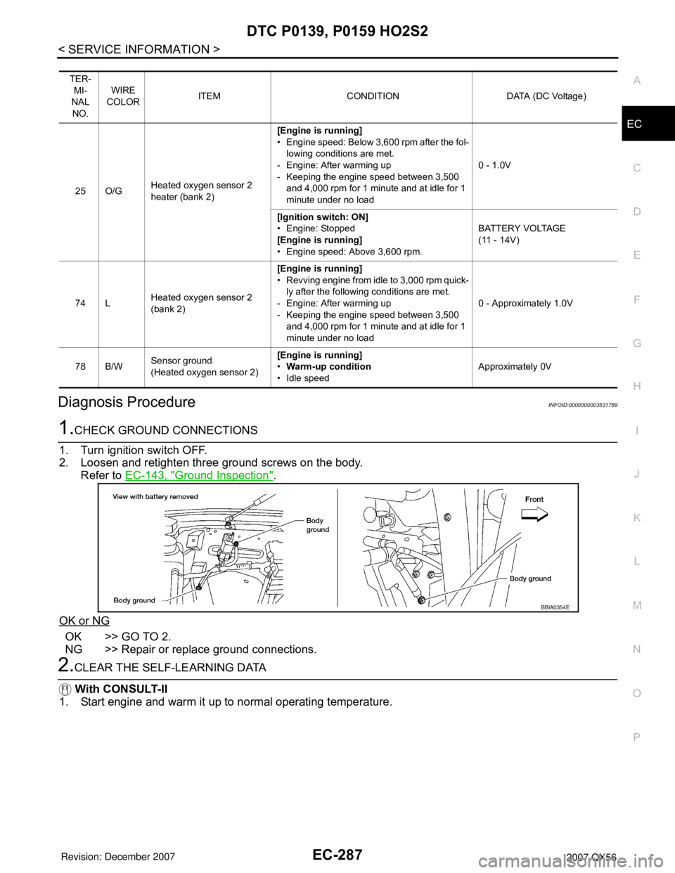
2. Loosen and retighten three ground screws on the body.
Refer to EC-143, "
Ground Inspection".
OK or NG
OK >> GO TO 2.
NG >> Repair or replace ground connections.
2.CLEAR THE SELF-LEARNING DATA
With CONSULT-II
1. Start engine and warm it up to normal operating temperature.
TER-
MI-
NAL
NO.WIRE
COLORITEM CONDITION DATA (DC Voltage)
25 O/GHeated oxygen sensor 2
heater (bank 2)[Engine is running]
• Engine speed: Below 3,600 rpm after the fol-
lowing conditions are met.
- Engine: After warming up
- Keeping the engine speed between 3,500
and 4,000 rpm for 1 minute and at idle for 1
minute under no load0 - 1.0V
[Ignition switch: ON]
• Engine: Stopped
[Engine is running]
• Engine speed: Above 3,600 rpm.BATTERY VOLTAGE
(11 - 14V)
74 LHeated oxygen sensor 2
(bank 2)[Engine is running]
• Revving engine from idle to 3,000 rpm quick-
ly after the following conditions are met.
- Engine: After warming up
- Keeping the engine speed between 3,500
and 4,000 rpm for 1 minute and at idle for 1
minute under no load0 - Approximately 1.0V
78 B/WSensor ground
(Heated oxygen sensor 2) [Engine is running]
•Warm-up condition
• Idle speed Approximately 0V
BBIA0354E
Page 1378 of 3061
DTC P0171, P0174 FUEL INJECTION SYSTEM FUNCTION
EC-295
< SERVICE INFORMATION >
C
D
E
F
G
H
I
J
K
L
MA
EC
N
P O
Do not use ECM ground terminals when measuring input/output voltage. Doing so may result in dam-
age to the ECM's transistor. Use a ground other than ECM terminals, such as the ground.
: Average voltage for pulse signal (Actual pulse signal can be confirmed by oscilloscope.)TER-
MI-
NAL
NO.WIRE
COLORITEM CONDITION DATA (DC Voltage)
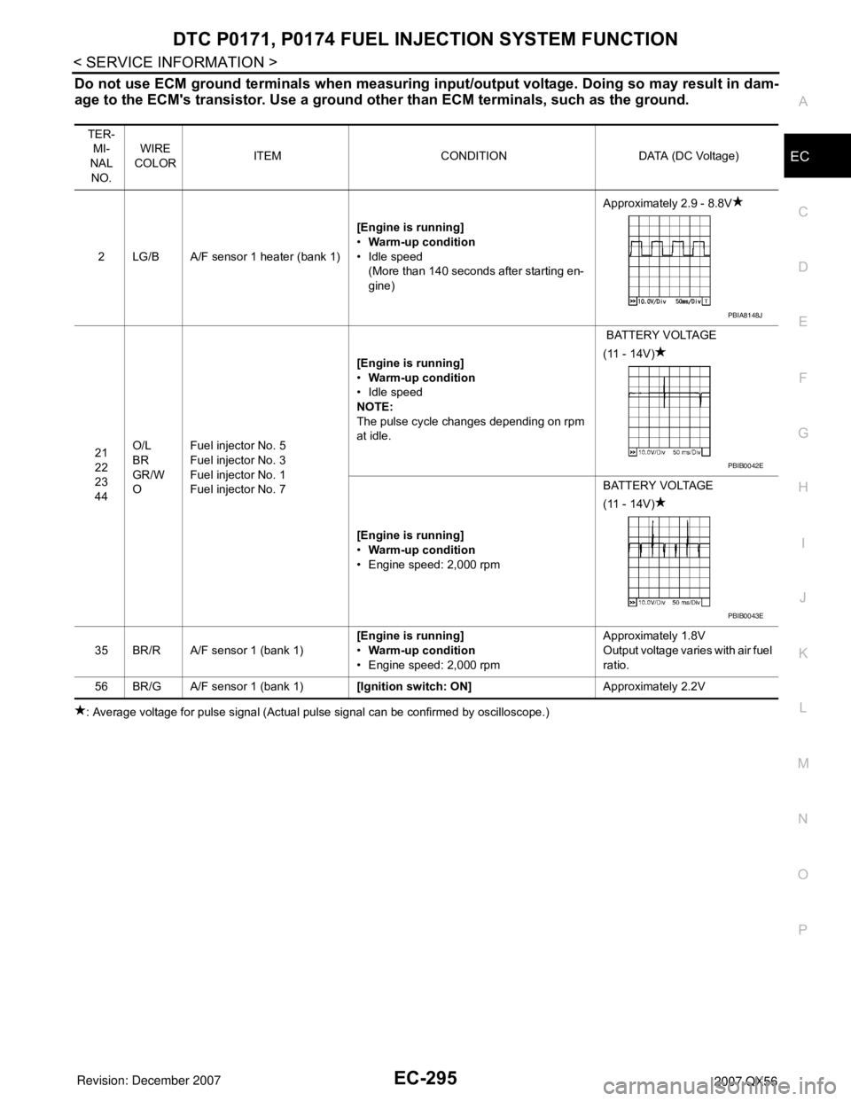
2 LG/B A/F sensor 1 heater (bank 1)[Engine is running]
•Warm-up condition
• Idle speed
(More than 140 seconds after starting en-
gine)Approximately 2.9 - 8.8V
21
22
23
44O/L
BR
GR/W
OFuel injector No. 5
Fuel injector No. 3
Fuel injector No. 1
Fuel injector No. 7[Engine is running]
•Warm-up condition
• Idle speed
NOTE:
The pulse cycle changes depending on rpm
at idle. BATTERY VOLTAGE
(11 - 14V)
[Engine is running]
•Warm-up condition
• Engine speed: 2,000 rpmBATTERY VOLTAGE
(11 - 14V)
35 BR/R A/F sensor 1 (bank 1)[Engine is running]
•Warm-up condition
• Engine speed: 2,000 rpmApproximately 1.8V
Output voltage varies with air fuel
ratio.
56 BR/G A/F sensor 1 (bank 1)[Ignition switch: ON]Approximately 2.2V
PBIA8148J
PBIB0042E
PBIB0043E
Page 1380 of 3061
DTC P0171, P0174 FUEL INJECTION SYSTEM FUNCTION
EC-297
< SERVICE INFORMATION >
C
D
E
F
G
H
I
J
K
L
MA
EC
N
P O
: Average voltage for pulse signal (Actual pulse signal can be confirmed by oscilloscope.)
Diagnosis ProcedureINFOID:0000000003531795
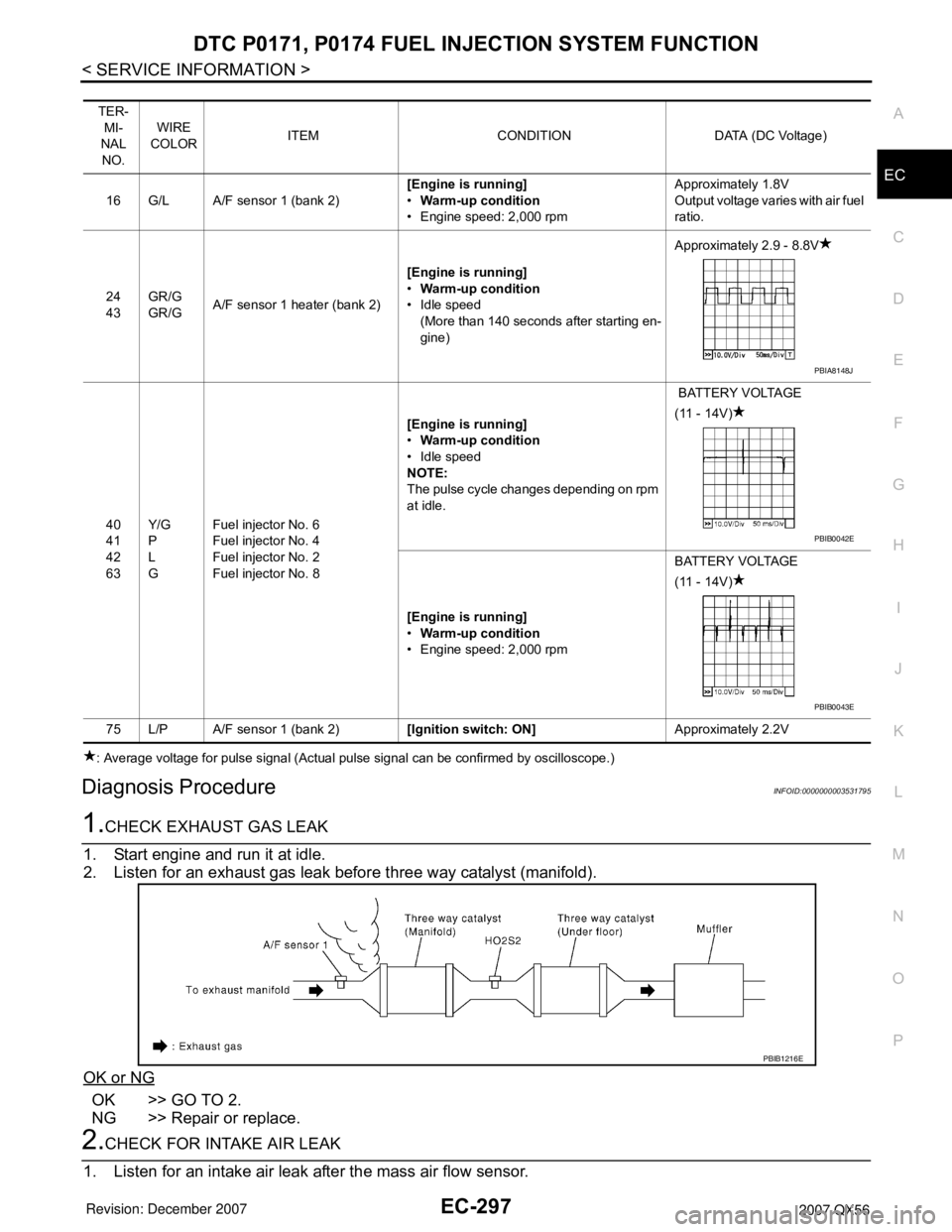
1.CHECK EXHAUST GAS LEAK
1. Start engine and run it at idle.
2. Listen for an exhaust gas leak before three way catalyst (manifold).
OK or NG
OK >> GO TO 2.
NG >> Repair or replace.
2.CHECK FOR INTAKE AIR LEAK
1. Listen for an intake air leak after the mass air flow sensor.
TER-
MI-
NAL
NO.WIRE
COLORITEM CONDITION DATA (DC Voltage)
16 G/L A/F sensor 1 (bank 2)[Engine is running]
•Warm-up condition
• Engine speed: 2,000 rpmApproximately 1.8V
Output voltage varies with air fuel
ratio.
24
43GR/G
GR/GA/F sensor 1 heater (bank 2)[Engine is running]
•Warm-up condition
• Idle speed
(More than 140 seconds after starting en-
gine)Approximately 2.9 - 8.8V
40
41
42
63Y/G
P
L
GFuel injector No. 6
Fuel injector No. 4
Fuel injector No. 2
Fuel injector No. 8[Engine is running]
•Warm-up condition
• Idle speed
NOTE:
The pulse cycle changes depending on rpm
at idle. BATTERY VOLTAGE
(11 - 14V)
[Engine is running]
•Warm-up condition
• Engine speed: 2,000 rpmBATTERY VOLTAGE
(11 - 14V)
75 L/P A/F sensor 1 (bank 2)[Ignition switch: ON]Approximately 2.2V
PBIA8148J
PBIB0042E
PBIB0043E
PBIB1216E
Page 1387 of 3061
EC-304
< SERVICE INFORMATION >
DTC P0172, P0175 FUEL INJECTION SYSTEM FUNCTION
Do not use ECM ground terminals when measuring input/output voltage. Doing so may result in dam-
age to the ECM's transistor. Use a ground other than ECM terminals, such as the ground.
: Average voltage for pulse signal (Actual pulse signal can be confirmed by oscilloscope.)TER-
MI-
NAL
NO.WIRE
COLORITEM CONDITION DATA (DC Voltage)
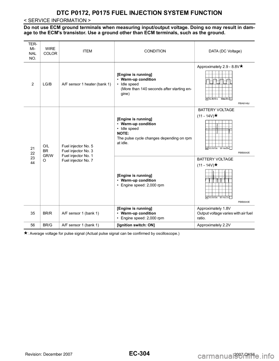
2 LG/B A/F sensor 1 heater (bank 1)[Engine is running]
•Warm-up condition
• Idle speed
(More than 140 seconds after starting en-
gine)Approximately 2.9 - 8.8V
21
22
23
44O/L
BR
GR/W
OFuel injector No. 5
Fuel injector No. 3
Fuel injector No. 1
Fuel injector No. 7[Engine is running]
•Warm-up condition
• Idle speed
NOTE:
The pulse cycle changes depending on rpm
at idle. BATTERY VOLTAGE
(11 - 14V)
[Engine is running]
•Warm-up condition
• Engine speed: 2,000 rpmBATTERY VOLTAGE
(11 - 14V)
35 BR/R A/F sensor 1 (bank 1)[Engine is running]
•Warm-up condition
• Engine speed: 2,000 rpmApproximately 1.8V
Output voltage varies with air fuel
ratio.
56 BR/G A/F sensor 1 (bank 1)[Ignition switch: ON]Approximately 2.2V
PBIA8148J
PBIB0042E
PBIB0043E
Page 1389 of 3061
EC-306
< SERVICE INFORMATION >
DTC P0172, P0175 FUEL INJECTION SYSTEM FUNCTION
: Average voltage for pulse signal (Actual pulse signal can be confirmed by oscilloscope.)
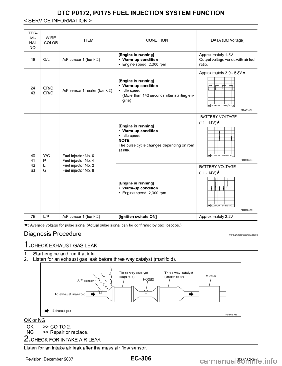
Diagnosis ProcedureINFOID:0000000003531799
1.CHECK EXHAUST GAS LEAK
1. Start engine and run it at idle.
2. Listen for an exhaust gas leak before three way catalyst (manifold).
OK or NG
OK >> GO TO 2.
NG >> Repair or replace.
2.CHECK FOR INTAKE AIR LEAK
Listen for an intake air leak after the mass air flow sensor.
TER-
MI-
NAL
NO.WIRE
COLORITEM CONDITION DATA (DC Voltage)
16 G/L A/F sensor 1 (bank 2)[Engine is running]
•Warm-up condition
• Engine speed: 2,000 rpmApproximately 1.8V
Output voltage varies with air fuel
ratio.
24
43GR/G
GR/GA/F sensor 1 heater (bank 2)[Engine is running]
•Warm-up condition
• Idle speed
(More than 140 seconds after starting en-
gine)Approximately 2.9 - 8.8V
40
41
42
63Y/G
P
L
GFuel injector No. 6
Fuel injector No. 4
Fuel injector No. 2
Fuel injector No. 8[Engine is running]
•Warm-up condition
• Idle speed
NOTE:
The pulse cycle changes depending on rpm
at idle. BATTERY VOLTAGE
(11 - 14V)
[Engine is running]
•Warm-up condition
• Engine speed: 2,000 rpmBATTERY VOLTAGE
(11 - 14V)
75 L/P A/F sensor 1 (bank 2)[Ignition switch: ON]Approximately 2.2V
PBIA8148J
PBIB0042E
PBIB0043E
PBIB1216E
Page 1401 of 3061
EC-318
< SERVICE INFORMATION >
DTC P0222, P0223 TP SENSOR
DTC P0222, P0223 TP SENSOR
Component DescriptionINFOID:0000000003531814
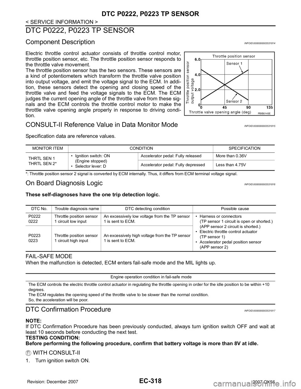
Electric throttle control actuator consists of throttle control motor,
throttle position sensor, etc. The throttle position sensor responds to
the throttle valve movement.
The throttle position sensor has the two sensors. These sensors are
a kind of potentiometers which transform the throttle valve position
into output voltage, and emit the voltage signal to the ECM. In addi-
tion, these sensors detect the opening and closing speed of the
throttle valve and feed the voltage signals to the ECM. The ECM
judges the current opening angle of the throttle valve from these sig-
nals and the ECM controls the throttle control motor to make the
throttle valve opening angle properly in response to driving condi-
tion.
CONSULT-II Reference Value in Data Monitor ModeINFOID:0000000003531815
Specification data are reference values.
*: Throttle position sensor 2 signal is converted by ECM internally. Thus, it differs from ECM terminal voltage signal.
On Board Diagnosis LogicINFOID:0000000003531816
These self-diagnoses have the one trip detection logic.
FA I L - S A F E M O D E
When the malfunction is detected, ECM enters fail-safe mode and the MIL lights up.
DTC Confirmation ProcedureINFOID:0000000003531817
NOTE:
If DTC Confirmation Procedure has been previously conducted, always turn ignition switch OFF and wait at
least 10 seconds before conducting the next test.
TESTING CONDITION:
Before performing the following procedure, confirm that battery voltage is more than 8V at idle.
WITH CONSULT-II
1. Turn ignition switch ON.
PBIB0145E
MONITOR ITEM CONDITION SPECIFICATION
THRTL SEN 1
THRTL SEN 2*• Ignition switch: ON
(Engine stopped)
• Selector lever: DAccelerator pedal: Fully released More than 0.36V
Accelerator pedal: Fully depressed Less than 4.75V
DTC No. Trouble diagnosis name DTC detecting condition Possible cause
P0222
0222Throttle position sensor
1 circuit low inputAn excessively low voltage from the TP sensor
1 is sent to ECM.• Harness or connectors
(TP sensor 1 circuit is open or shorted.)
(APP sensor 2 circuit is shorted.)
• Electric throttle control actuator
(TP sensor 1)
• Accelerator pedal position sensor
(APP sensor 2) P0223
0223Throttle position sensor
1 circuit high inputAn excessively high voltage from the TP sensor
1 is sent to ECM.
Engine operation condition in fail-safe mode
The ECM controls the electric throttle control actuator in regulating the throttle opening in order for the idle position to be within +10
degrees.
The ECM regulates the opening speed of the throttle valve to be slower than the normal condition.
So, the acceleration will be poor.
Page 1415 of 3061
EC-332
< SERVICE INFORMATION >
DTC P0327, P0328, P0332, P0333 KS
DTC P0327, P0328, P0332, P0333 KS
Component DescriptionINFOID:0000000003531825
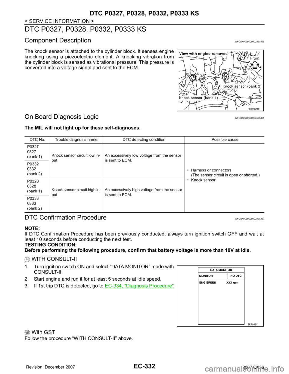
The knock sensor is attached to the cylinder block. It senses engine
knocking using a piezoelectric element. A knocking vibration from
the cylinder block is sensed as vibrational pressure. This pressure is
converted into a voltage signal and sent to the ECM.
On Board Diagnosis LogicINFOID:0000000003531826
The MIL will not light up for these self-diagnoses.
DTC Confirmation ProcedureINFOID:0000000003531827
NOTE:
If DTC Confirmation Procedure has been previously conducted, always turn ignition switch OFF and wait at
least 10 seconds before conducting the next test.
TESTING CONDITION:
Before performing the following procedure, confirm that battery voltage is more than 10V at idle.
WITH CONSULT-II
1. Turn ignition switch ON and select “DATA MONITOR” mode with
CONSULT-II.
2. Start engine and run it for at least 5 seconds at idle speed.
3. If 1st trip DTC is detected, go to EC-334, "
Diagnosis Procedure"
With GST
Follow the procedure “WITH CONSULT-II” above.
PBIB0021E
DTC No. Trouble diagnosis name DTC detecting condition Possible cause
P0327
0327
(bank 1)Knock sensor circuit low in-
putAn excessively low voltage from the sensor
is sent to ECM.
• Harness or connectors
(The sensor circuit is open or shorted.)
• Knock sensor P0332
0332
(bank 2)
P0328
0328
(bank 1)Knock sensor circuit high in-
putAn excessively high voltage from the sensor
is sent to ECM.
P0333
0333
(bank 2)
SEF058Y