Page 1776 of 3061
EM-6
< SERVICE INFORMATION >
PREPARATION
PREPARATION
Special Service ToolINFOID:0000000003531516
The actual shapes of Kent-Moore tools may differ from those of special service tools illustrated here.
Tool number
(Kent-Moore No.)
Tool name Description
K V 1 0 1111 0 0
(J-37228)
Seal cutter Removing steel oil pan and rear timing chain
case
—
(J-44626)
Air fuel sensor Socket Loosening or tightening air fuel ratio A/F sen-
sor
a: 22 mm (0.87 in)
EG15050500
(J-45402)
Compression gauge adapter Inspecting compression pressure
KV10116200
(J-26336-A)
Valve spring compressor
1. KV10115900
(J-26336-20)
Attachment
2. KV10109220
(—)
Adapter Disassembling valve mechanism
Part (1) is a component of KV10116200 (J-
26336-A), but part (2) is not.
KV10112100
(BT-8653-A)
Angle wrench Tightening bolts for cylinder head, main bear-
ing cap and connecting rod cap
KV10107902
(J-38959)
Valve oil seal puller Removing valve oil seal
S-NT046
LBIA0444E
ZZA1225D
PBIC1650E
S-NT014
S-NT011
Page 1777 of 3061
PREPARATIONEM-7
< SERVICE INFORMATION >
C
DE
F
G H
I
J
K L
M A
EM
NP
O
KV10115600
(J-38958)
Valve oil seal drift
Installing valve oil seal
Use side A.
a: 20 (0.79) dia. d: 8 (0.31) dia.
b: 13 (0.51) dia. e: 10.7 (0.421) dia.
c: 10.3 (0.406) dia. f: 5 (0.20) dia.
Unit: mm (in)
EM03470000
(J-8037)
Piston ring compressor Installing piston assembly into cylinder bore
ST16610001
(J-23907)
Pilot bushing puller Removing crankshaft pilot bushing
WS39930000
(—)
Tube presser Pressing the tube of liquid gasket
—
(J-47245)
Ring gear stopper Removing and installing crankshaft pulley
16441 6N210
(J-45488)
Quick connector release Removing fuel tube quick connectors in en-
gine room
(Available in SEC. 164 of PARTS CATALOG:
Part No. 16441 6N210)
—
(J-46535)
Drive belt tension releaser Releasing drive belt tension
Tool number
(Kent-Moore No.)
Tool name
Description
S-NT603
S-NT044
S-NT045
S-NT052
LBIA0451E
PBIC0198E
WBIA0536E
Page 1779 of 3061

PREPARATIONEM-9
< SERVICE INFORMATION >
C
DE
F
G H
I
J
K L
M A
EM
NP
O
Valve guide drift Removing and installing valve guide
Intake & Exhaust:
a: 9.5 mm (0.374 in) dia.
b: 5.5 mm (0.217 in) dia.
Valve guide reamer 1: Reaming valve guide hole 2: Reaming hole for oversize valve guide
Intake & Exhaust:
d
1: 6.0 mm (0.236 in) dia.
d
2: 10.175 - 10.196 mm (0.4006 - 0.4014 in)
dia.
Front oil seal drift Installing front oil seal
Rear oil seal drift Installing rear oil seal
(J-43897-18)
(J-43897-12)
Oxygen sensor thread cleaner Reconditioning the exhaust system threads
before installing a new A/F sensor and heated
oxygen sensor (Use with anti-seize lubricant
shown below.)
a: J-43897-18 (18 mm dia.) (0.71 in) for zir-
conia heated oxygen sensor
b: J-43897-12 (12 mm dia.) (0.55 in) for tita-
nia heated oxygen sensor
Anti-seize lubricant (Permatex 133AR
or equivalent meeting MIL specifica-
tion MIL-A-907) Lubricating A/F sensors and heated oxygen
sensor thread cleaning tool when recondition-
ing exhaust system threads
(Kent-Moore No.)
Tool name
Description
S-NT015
S-NT016
ZZA0012D
ZZA0025D
AEM488
AEM489
Page 1781 of 3061

NOISE, VIBRATION AND HARSHNESS (NVH) TROUBLESHOOTINGEM-11
< SERVICE INFORMATION >
C
DE
F
G H
I
J
K L
M A
EM
NP
O
Use the Chart Below to Help You
Find the Cause of the SymptomINFOID:0000000003531519
1. Locate the area where noise occurs.
2. Confirm the type of noise.
3. Specify the operating condition of engine.
4. Check specified noise source.
If necessary, repair or replace these parts.
A: Closely related B: Related C: Sometimes related —: Not relatedB. Tappet noise C. Camshaft bearing noise D. Valve mechanism
E. Rotation mechanism F. Piston pin noise G. Piston slap noise
H. Main bearing noise I. Connecting rod bearing noise J. Drive belt noise (slipping)
K. Drive belt noise (stick/slipping) L. Water pump noise M. Timing chain and chain tensioner noise
Location of noise Ty p e o f
noise Operating condition of engine
Source of noise Check item
Refer-
ence page
Be-
fore
warm- up After
warm-
up When
start-
ing When
idling When
racing While
driv-
ing
Top of en-
gine
Rocker cov-
er
Cylinder
head Ticking or
clicking
C A — A B — Tappet noise Valve clearance
EM-56
Rattle C A — A B CCamshaft
bearing noiseCamshaft journal clear-
ance
Camshaft runout EM-46EM-46
Crankshaft
pulley
Cylinder
block (Side
of engine)
Oil panSlap or
knock
—A—B B— Piston pin
noisePiston and piston pin
clearance
Connecting rod bushing
clearance EM-93
EM-93
Slap or
rap
A——B B A Piston slap
noisePiston-to-bore clear-
ance
Piston ring side clear-
ance
Piston ring end gap
Connecting rod bend
and torsion EM-93EM-93
EM-93
EM-93
Knock A B C B B B
Connecting
rod bearing
noiseConnecting rod bushing
oil clearance (Small
end)
Connecting rod bearing
clearance (Big end)
EM-93EM-93
Knock A B — A B C
Main bearing
noiseMain bearing oil clear-
ance
Crankshaft runout EM-93EM-93
Front of en-
gine
Chain case
cover
Front coverTapping
or ticking
AA—BBB Timing chain
and chain
tensioner
noiseTiming chain cracks
and wear
Timing chain tensioner
operation
EM-38
EM-38
Front of en-
gineSqueak-
ing or
fizzing
AB—B—C
Drive belts
(Sticking or
slipping)Drive belts deflection
EM-13Creaking A B A B A B Drive belts
(Slipping)Idler pulley bearing op-
eration
Squall
Creaking AB—BAB Water pump
noiseWater pump operation
EM-38
Rattle — — A — — — VTC VTC lockpin clearance EM-55
Page 1789 of 3061

INTAKE MANIFOLDEM-19
< SERVICE INFORMATION >
C
DE
F
G H
I
J
K L
M A
EM
NP
O
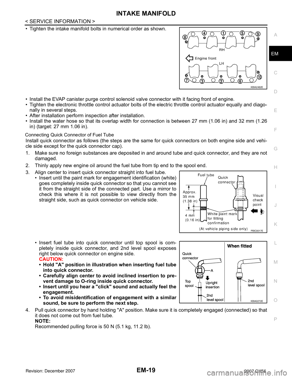
• Tighten the intake manifold bolts in numerical order as shown.
• Install the EVAP canister purge control solenoi
d valve connector with it facing front of engine.
• Tighten the electronic throttle control actuator bolts of the electric throttle control actuator equally and diago-
nally in several steps.
• After installation perform inspection after installation.
• Install the water hose so that its overlap width for connection is between 27 mm (1.06 in) and 32 mm (1.26
in) (target: 27 mm 1.06 in).
Connecting Quick Connector of Fuel Tube
Install quick connector as follows (the steps are the same for quick connectors on both engine side and vehi-
cle side except for the quick connector cap).
1. Make sure no foreign substances are deposited in and around tube and quick connector, and they are not
damaged.
2. Thinly apply new engine oil around the fuel tube from tip end to the spool end.
3. Align center to insert quick connector straight into fuel tube. • Insert until the paint mark for engagement identification (white)
goes completely inside quick connector so that you cannot see
it from the straight side of the connected part. Use a mirror to
check this where it is not possible to view directly from the
straight side, such as quick connector on vehicle side.
• Insert fuel tube into quick connector until top spool is com- pletely inside quick connector, and 2nd level spool exposes
right below quick connector on engine side.
CAUTION:
• Hold "A" position in illustration when inserting fuel tubeinto quick connector.
• Carefully align center to avoid inclined insertion to pre-
vent damage to O-ring inside quick connector.
• Insert until you hear a "click" sound and actually feel the engagement.
• To avoid misidentification of engagement with a similar
sound, be sure to perform the next step.
4. Pull quick connector by hand holding "A" position. Make sure it is completely engaged (connected) so that it does not come out from fuel tube.
NOTE:
Recommended pulling force is 50 N (5.1 kg, 11.2 lb).
KBIA2462E
PBIC0017E
KBIA0272E
Page 1792 of 3061

EM-22
< ON-VEHICLE REPA IR >
EXHAUST MANIFOLD AND THREE WAY CATALYST
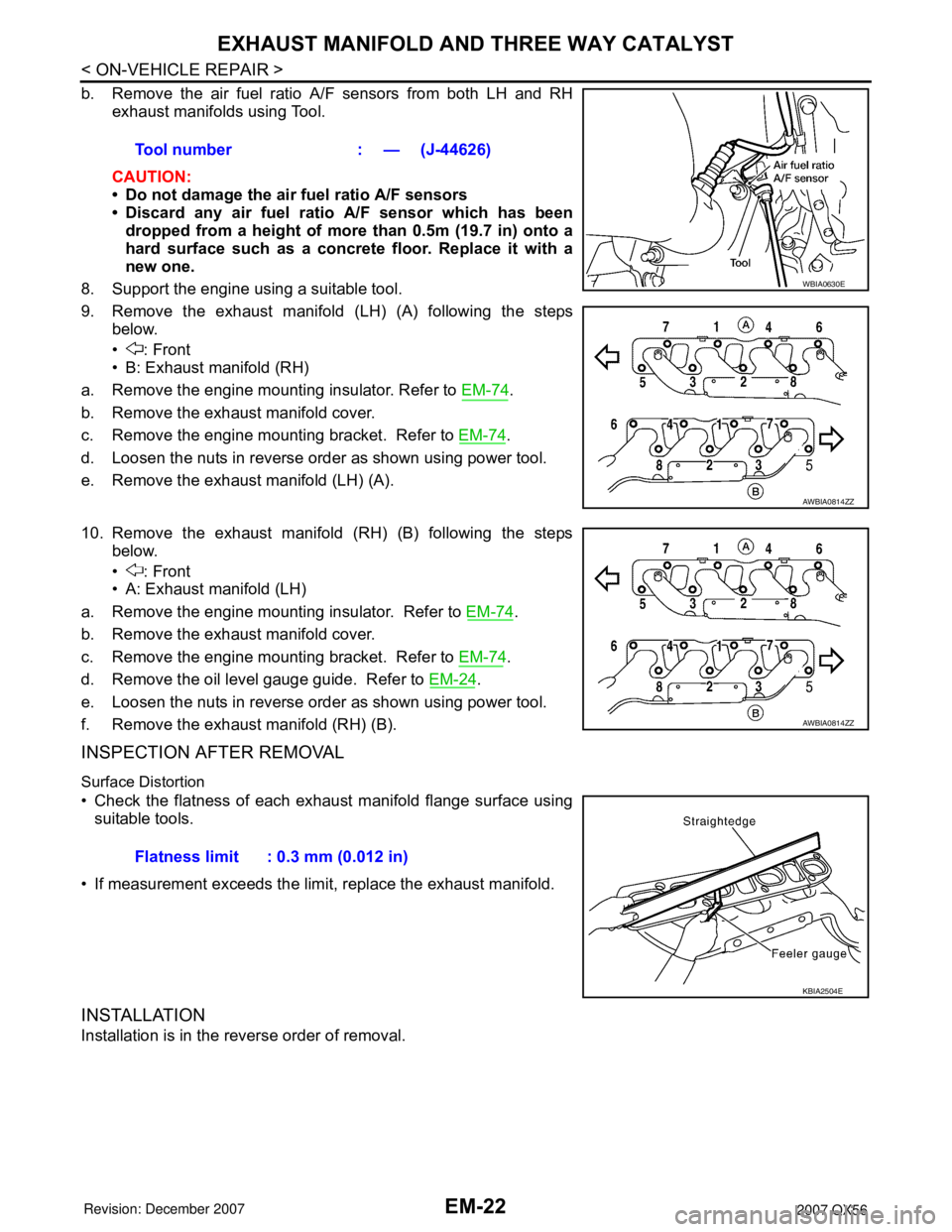
b. Remove the air fuel ratio A /F sensors from both LH and RH
exhaust
manifolds using T ool.
CAUTIO
N:
•Do not damage the air fuel ratio A/F sensors
•D iscard any air fuel ratio A /F sensor which h as been
dr
opped from a heig ht of more than 0.5m ( 19.7 in) onto a
h ard surface such as a c on crete floor. Re place it with a
new one.
8. Support the engine using a suitable t ool.
9. Remove the exhaust manifold (LH) (A) following the steps
belo
w.
•: Front
•B: Exhaust manifold (RH)
a. Remove the engine mounting insulator. Refer to EM-74.
b. Remove the exhaust manif old cover.
c. Remove the engine mounting bracket. Refer to EM-74.
d. Loosen the nuts in reverse order as shown using power tool.
e. Remove the exhaust manifold (LH) (A).
10
. Remove the exhaust manifold (RH) (B) following the steps
belo
w.
•: Front
•A: Exhaust manifold (LH)
a. Remove the engine mounting insulator. Refer to EM-74.
b. Remove the exhaust manif old c over.
c. Remove the engine mounting bracket. Refer to EM-74.
d. Remove the oil level gauge guide. Refer to EM-24.
e. Loosen the nuts in reverse order as shown using power tool.
f. Remove the ex hau st manif old (RH) (B).
INSP ECTION AFTER REMOVAL
Surface Distortion
•C heck the flatness of each exhaust manifold flange surface using
sui
t able tools.
•If measurement exc eeds the limi t, replace the exhaust manifold.
INST ALLA TION
Installation is in the reverse order of removal.
To ol number: — (J-4 4626)
WBIA 0630E
AW BIA0814ZZ
AW BIA0814ZZ
Fl atness limit: 0.3 mm (0. 012 in)
KBIA 2504E
Page 1794 of 3061
EM-24
< SERVICE INFORMATION >
OIL PAN AND OIL STRAINER
OIL PAN AND OIL STRAINER
Removal and InstallationINFOID:0000000003531528
REMOVAL
WARNING:
To avoid the danger of being scalded, never drain the engine oil when the engine is hot.
1. Remove the engine. Refer to EM-74, "
Removal and Installation".
2. Remove the oil pan (lower) using the following steps.
a. Remove the oil pan (lower) bolts using power tool.
1. Oil pan (upper) 2. O-ring 3. O-ring
4. O-ring 5. O-ring (with collar) 6. Oil level gauge guide
7. Oil level gauge 8. O-ring 9. Connector bolt
10. Oil filter 11. Oil cooler 12. Relief valve
13. Oil pressure switch 14. Gasket 15. Drain plug
16. Oil pan (lower) 17. Oil strainer
KBIA2465E
KBIA2466E
Page 1795 of 3061
OIL PAN AND OIL STRAINEREM-25
< SERVICE INFORMATION >
C
DE
F
G H
I
J
K L
M A
EM
NP
O
b. Insert Tool between the lower oil pan and the upper oil pan.
CAUTION:
• Be careful not to damage the mating surface.
• Do not insert a screwdriver, this will damage the matingsurfaces.
c. Slide (1) the Tool by tapping (2) its side with a hammer to remove the lower oil pan from the upper oil pan.
3. Remove the oil strainer from the oil pan (upper).
4. Remove the oil pan (upper) using the following steps.
a. Remove the oil pan (upper) bolts a shown.
b. Remove the oil pan (upper) from the cylinder block by prying it at the points shown, using suitable tool.
CAUTION:
Do not damage mating surface.
5. Remove the O-rings from the oil pump and front cover. NOTE:
Do not reuse O-rings.
INSPECTION AFTER REMOVAL
Clean the oil strainer.
INSTALLATION
Tool number : KV10111100 (J-37228)
WBIA0566E
KBIA2467E
KBIA2468E
KBIA2469E