Page 1283 of 3061
EC-200
< SERVICE INFORMATION >
DTC P0102, P0103 MAF SENSOR
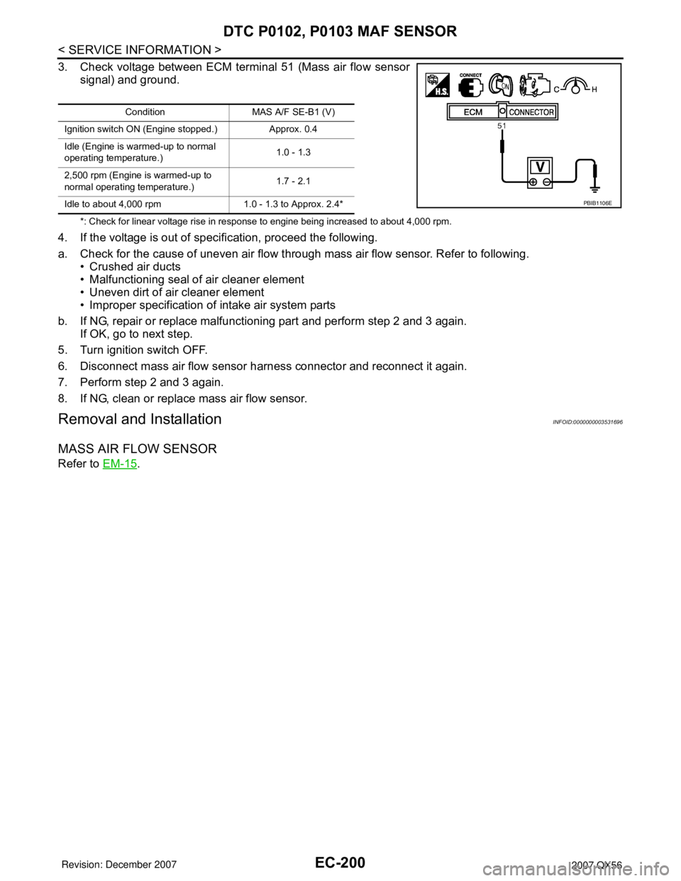
3. Check voltage between ECM terminal 51 (Mass air flow sensor
signal) and ground.
*: Check for linear voltage rise in response to engine being increased to about 4,000 rpm.
4. If the voltage is out of specification, proceed the following.
a. Check for the cause of uneven air flow through mass air flow sensor. Refer to following.
• Crushed air ducts
• Malfunctioning seal of air cleaner element
• Uneven dirt of air cleaner element
• Improper specification of intake air system parts
b. If NG, repair or replace malfunctioning part and perform step 2 and 3 again.
If OK, go to next step.
5. Turn ignition switch OFF.
6. Disconnect mass air flow sensor harness connector and reconnect it again.
7. Perform step 2 and 3 again.
8. If NG, clean or replace mass air flow sensor.
Removal and InstallationINFOID:0000000003531696
MASS AIR FLOW SENSOR
Refer to EM-15.
Condition MAS A/F SE-B1 (V)
Ignition switch ON (Engine stopped.) Approx. 0.4
Idle (Engine is warmed-up to normal
operating temperature.)1.0 - 1.3
2,500 rpm (Engine is warmed-up to
normal operating temperature.)1.7 - 2.1
Idle to about 4,000 rpm 1.0 - 1.3 to Approx. 2.4*
PBIB1106E
Page 1291 of 3061
EC-208
< SERVICE INFORMATION >
DTC P0117, P0118 ECT SENSOR
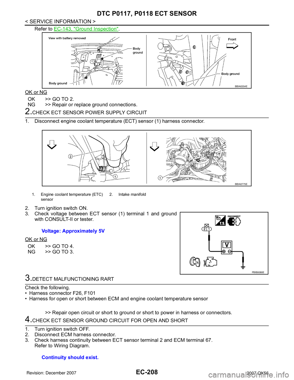
Refer to EC-143, "Ground Inspection".
OK or NG
OK >> GO TO 2.
NG >> Repair or replace ground connections.
2.CHECK ECT SENSOR POWER SUPPLY CIRCUIT
1. Disconnect engine coolant temperature (ECT) sensor (1) harness connector.
2. Turn ignition switch ON.
3. Check voltage between ECT sensor (1) terminal 1 and ground
with CONSULT-II or tester.
OK or NG
OK >> GO TO 4.
NG >> GO TO 3.
3.DETECT MALFUNCTIONING RART
Check the following.
• Harness connector F26, F101
• Harness for open or short between ECM and engine coolant temperature sensor
>> Repair open circuit or short to ground or short to power in harness or connectors.
4.CHECK ECT SENSOR GROUND CIRCUIT FOR OPEN AND SHORT
1. Turn ignition switch OFF.
2. Disconnect ECM harness connector.
3. Check harness continuity between ECT sensor terminal 2 and ECM terminal 67.
Refer to Wiring Diagram.
BBIA0354E
1. Engine coolant temperature (ETC)
sensor2. Intake manifold
Voltage: Approximately 5V
BBIA0775E
PBIB0080E
Continuity should exist.
Page 1292 of 3061
DTC P0117, P0118 ECT SENSOR
EC-209
< SERVICE INFORMATION >
C
D
E
F
G
H
I
J
K
L
MA
EC
N
P O
4. Also check harness for short to ground and short to power.
OK or NG
OK >> GO TO 6.
NG >> GO TO 5.
5.DETECT MALFUNCTIONING PART
Check the following.
• Harness connector F26, F101
• Harness for open and short between ECT sensor and ECM
>> Repair open circuit or short to ground or short to power in harness or connectors.
6.CHECK ENGINE COOLANT TEMPERATURE SENSOR
Refer to EC-209, "
Component Inspection".
OK or NG
OK >> GO TO 7.
NG >> Replace engine coolant temperature sensor.
7.CHECK INTERMITTENT INCIDENT
Refer to EC-138
.
>>INSPECTION END
Component InspectionINFOID:0000000003531709
ENGINE COOLANT TEMPERATURE SENSOR
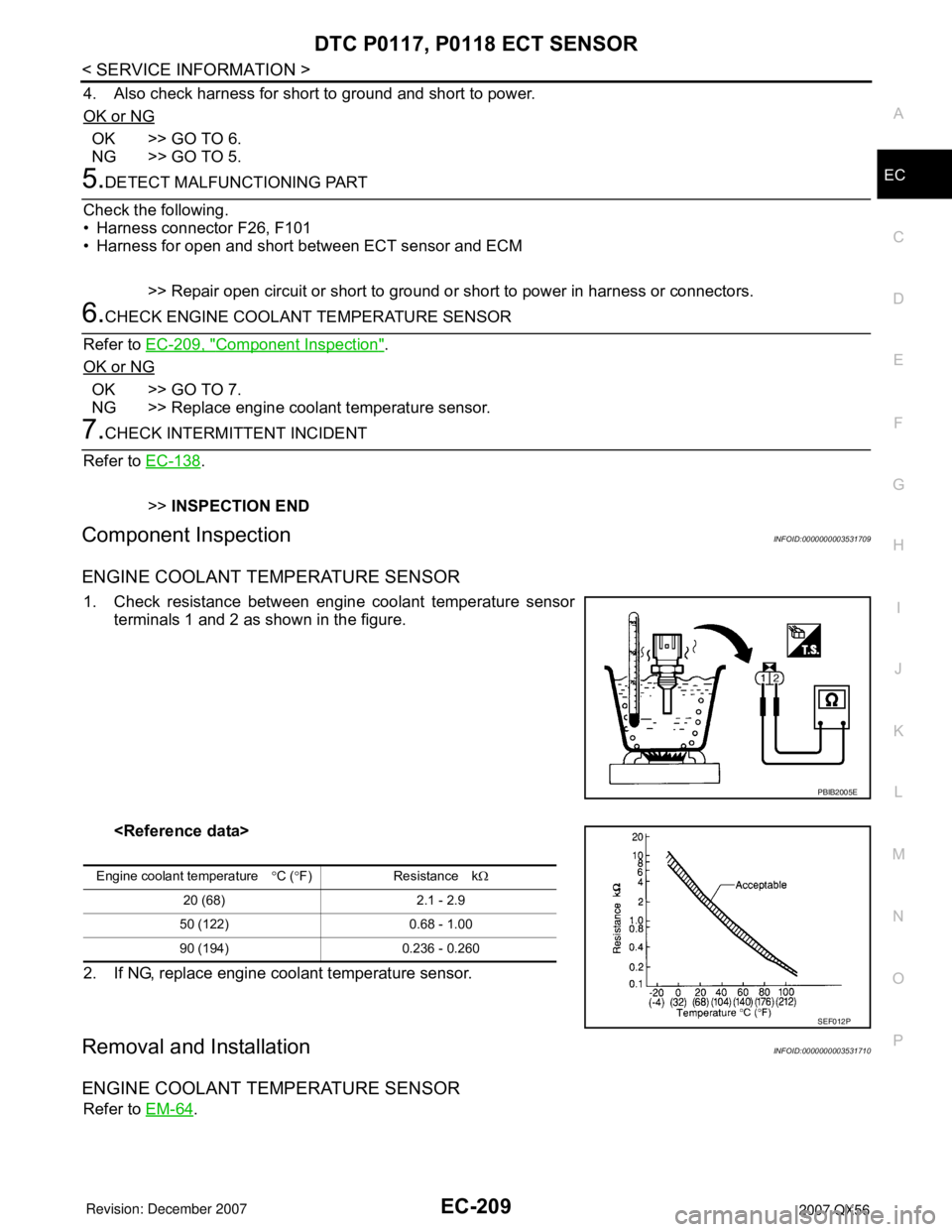
1. Check resistance between engine coolant temperature sensor
terminals 1 and 2 as shown in the figure.
2. If NG, replace engine coolant temperature sensor.
Removal and InstallationINFOID:0000000003531710
ENGINE COOLANT TEMPERATURE SENSOR
Refer to EM-64.
PBIB2005E
Engine coolant temperature°C (°F) Resistance kΩ
20 (68) 2.1 - 2.9
50 (122) 0.68 - 1.00
90 (194) 0.236 - 0.260
SEF012P
Page 1296 of 3061
DTC P0122, P0123 TP SENSOR
EC-213
< SERVICE INFORMATION >
C
D
E
F
G
H
I
J
K
L
MA
EC
N
P O
Diagnosis ProcedureINFOID:0000000003531716
1.CHECK GROUND CONNECTIONS
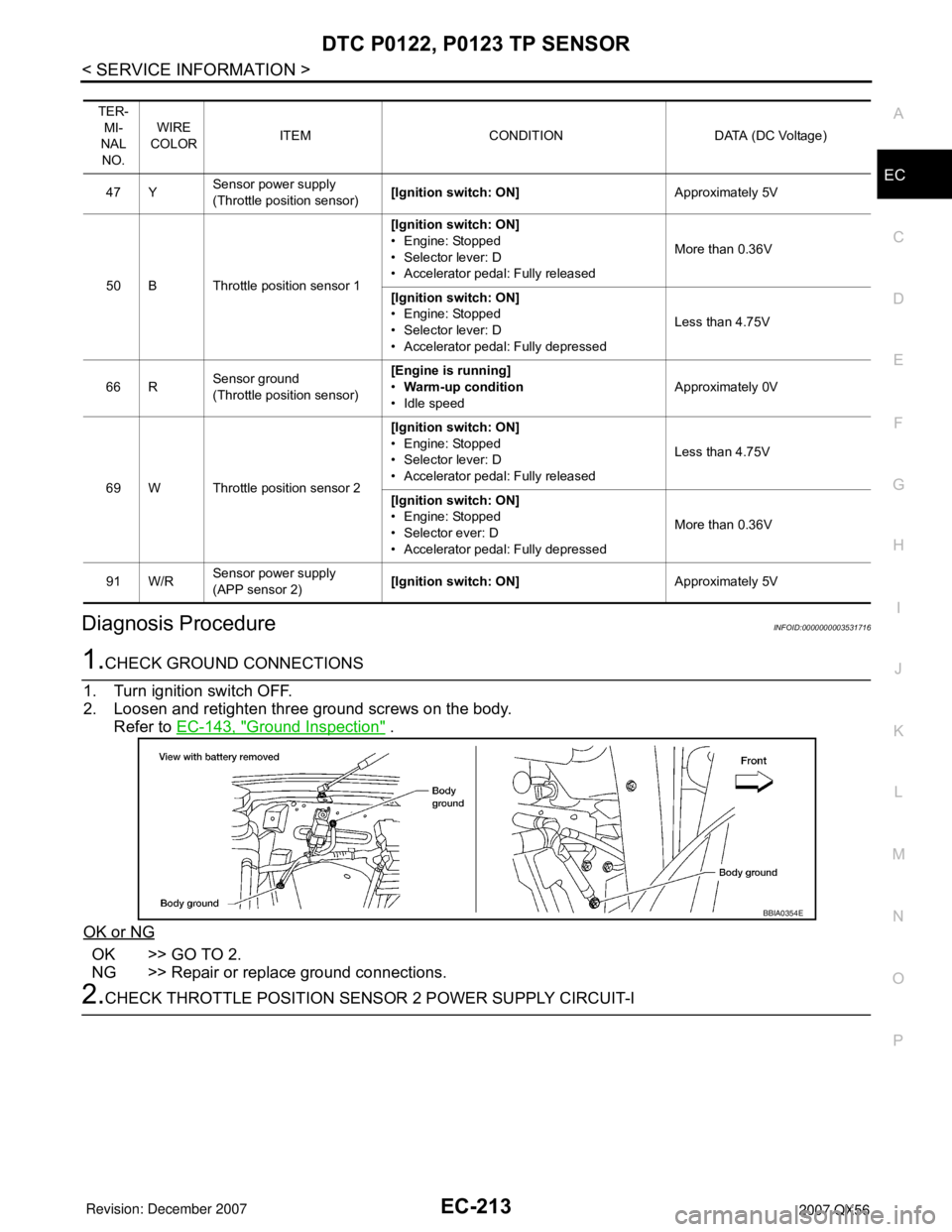
1. Turn ignition switch OFF.
2. Loosen and retighten three ground screws on the body.
Refer to EC-143, "
Ground Inspection" .
OK or NG
OK >> GO TO 2.
NG >> Repair or replace ground connections.
2.CHECK THROTTLE POSITION SENSOR 2 POWER SUPPLY CIRCUIT-I
TER-
MI-
NAL
NO.WIRE
COLORITEM CONDITION DATA (DC Voltage)
47 YSensor power supply
(Throttle position sensor)[Ignition switch: ON]Approximately 5V
50 B Throttle position sensor 1[Ignition switch: ON]
• Engine: Stopped
• Selector lever: D
• Accelerator pedal: Fully releasedMore than 0.36V
[Ignition switch: ON]
• Engine: Stopped
• Selector lever: D
• Accelerator pedal: Fully depressedLess than 4.75V
66 RSensor ground
(Throttle position sensor)[Engine is running]
•Warm-up condition
• Idle speedApproximately 0V
69 W Throttle position sensor 2[Ignition switch: ON]
• Engine: Stopped
• Selector lever: D
• Accelerator pedal: Fully releasedLess than 4.75V
[Ignition switch: ON]
• Engine: Stopped
• Selector ever: D
• Accelerator pedal: Fully depressedMore than 0.36V
91 W/RSensor power supply
(APP sensor 2)[Ignition switch: ON]Approximately 5V
BBIA0354E
Page 1300 of 3061
DTC P0125 ECT SENSOR
EC-217
< SERVICE INFORMATION >
C
D
E
F
G
H
I
J
K
L
MA
EC
N
P O
DTC P0125 ECT SENSOR
Component DescriptionINFOID:0000000003531719
NOTE:
If DTC P0125 is displayed with P0117 or P0118, first perform the trouble diagnosis for DTC P0117 or
P0118. Refer to EC-205
.
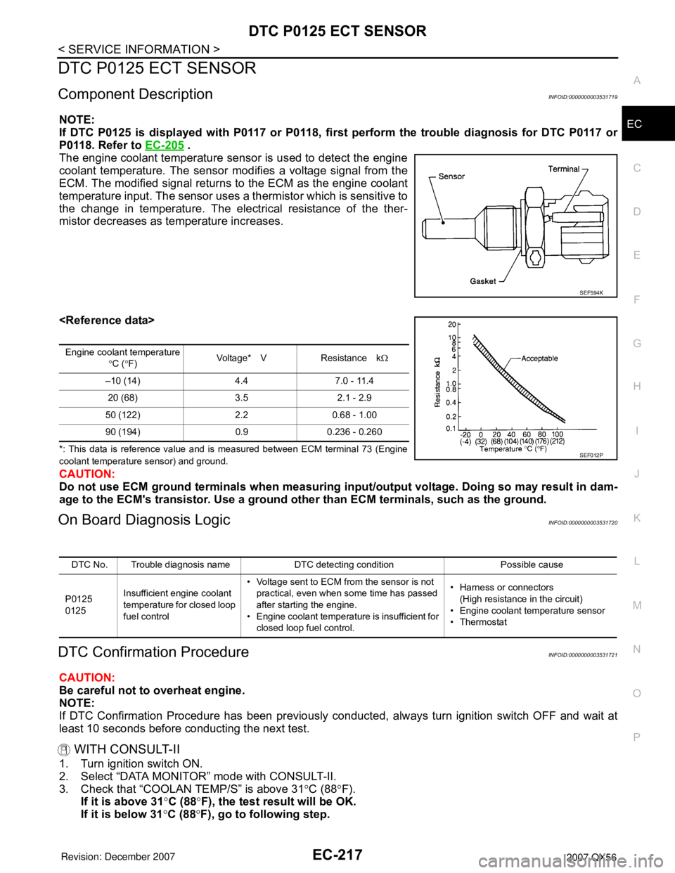
The engine coolant temperature sensor is used to detect the engine
coolant temperature. The sensor modifies a voltage signal from the
ECM. The modified signal returns to the ECM as the engine coolant
temperature input. The sensor uses a thermistor which is sensitive to
the change in temperature. The electrical resistance of the ther-
mistor decreases as temperature increases.
*: This data is reference value and is measured between ECM terminal 73 (Engine
coolant temperature sensor) and ground.
CAUTION:
Do not use ECM ground terminals when measuring input/output voltage. Doing so may result in dam-
age to the ECM's transistor. Use a ground other than ECM terminals, such as the ground.
On Board Diagnosis LogicINFOID:0000000003531720
DTC Confirmation ProcedureINFOID:0000000003531721
CAUTION:
Be careful not to overheat engine.
NOTE:
If DTC Confirmation Procedure has been previously conducted, always turn ignition switch OFF and wait at
least 10 seconds before conducting the next test.
WITH CONSULT-II
1. Turn ignition switch ON.
2. Select “DATA MONITOR” mode with CONSULT-II.
3. Check that “COOLAN TEMP/S” is above 31°C (88°F).
If it is above 31°C (88°F), the test result will be OK.
If it is below 31°C (88°F), go to following step.
SEF594K
Engine coolant temperature
°C (°F)Voltage* V Resistance kΩ
–10 (14) 4.4 7.0 - 11.4
20 (68) 3.5 2.1 - 2.9
50 (122) 2.2 0.68 - 1.00
90 (194) 0.9 0.236 - 0.260
SEF012P
DTC No. Trouble diagnosis name DTC detecting condition Possible cause
P0125
0125Insufficient engine coolant
temperature for closed loop
fuel control• Voltage sent to ECM from the sensor is not
practical, even when some time has passed
after starting the engine.
• Engine coolant temperature is insufficient for
closed loop fuel control.• Harness or connectors
(High resistance in the circuit)
• Engine coolant temperature sensor
•Thermostat
Page 1301 of 3061
EC-218
< SERVICE INFORMATION >
DTC P0125 ECT SENSOR
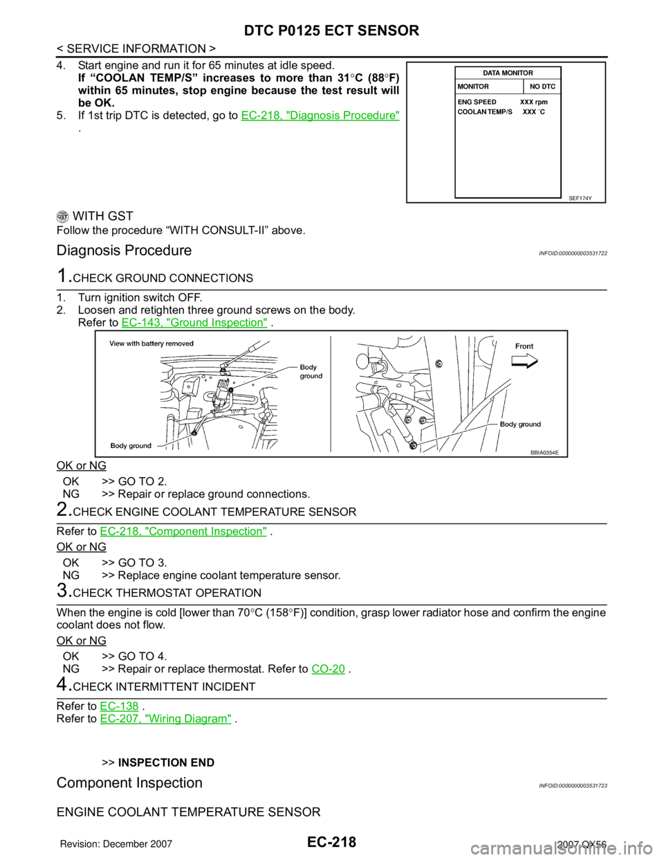
4. Start engine and run it for 65 minutes at idle speed.
If “COOLAN TEMP/S” increases to more than 31°C (88°F)
within 65 minutes, stop engine because the test result will
be OK.
5. If 1st trip DTC is detected, go to EC-218, "
Diagnosis Procedure"
.
WITH GST
Follow the procedure “WITH CONSULT-II” above.
Diagnosis ProcedureINFOID:0000000003531722
1.CHECK GROUND CONNECTIONS
1. Turn ignition switch OFF.
2. Loosen and retighten three ground screws on the body.
Refer to EC-143, "
Ground Inspection" .
OK or NG
OK >> GO TO 2.
NG >> Repair or replace ground connections.
2.CHECK ENGINE COOLANT TEMPERATURE SENSOR
Refer to EC-218, "
Component Inspection" .
OK or NG
OK >> GO TO 3.
NG >> Replace engine coolant temperature sensor.
3.CHECK THERMOSTAT OPERATION
When the engine is cold [lower than 70°C (158°F)] condition, grasp lower radiator hose and confirm the engine
coolant does not flow.
OK or NG
OK >> GO TO 4.
NG >> Repair or replace thermostat. Refer to CO-20
.
4.CHECK INTERMITTENT INCIDENT
Refer to EC-138
.
Refer to EC-207, "
Wiring Diagram" .
>>INSPECTION END
Component InspectionINFOID:0000000003531723
ENGINE COOLANT TEMPERATURE SENSOR
SEF174Y
BBIA0354E
Page 1302 of 3061
DTC P0125 ECT SENSOR
EC-219
< SERVICE INFORMATION >
C
D
E
F
G
H
I
J
K
L
MA
EC
N
P O
1. Check resistance between engine coolant temperature sensor
terminals 1 and 2 as shown in the figure.
2. If NG, replace engine coolant temperature sensor.
Removal and InstallationINFOID:0000000003531724
ENGINE COOLANT TEMPERATURE SENSOR
Refer to CO-20 .
PBIB2005E
Engine coolant temperature°C (°F) Resistance kΩ
20 (68) 2.1 - 2.9
50 (122) 0.68 - 1.00
90 (194) 0.236 - 0.260
SEF012P
Page 1304 of 3061
DTC P0127 IAT SENSOR
EC-221
< SERVICE INFORMATION >
C
D
E
F
G
H
I
J
K
L
MA
EC
N
P O
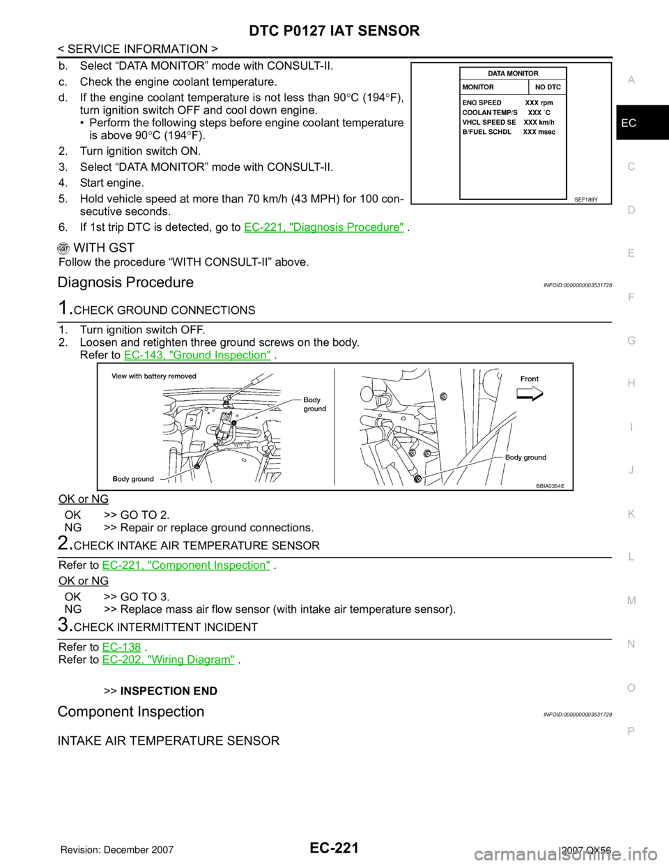
b. Select “DATA MONITOR” mode with CONSULT-II.
c. Check the engine coolant temperature.
d. If the engine coolant temperature is not less than 90°C (194°F),
turn ignition switch OFF and cool down engine.
• Perform the following steps before engine coolant temperature
is above 90°C (194°F).
2. Turn ignition switch ON.
3. Select “DATA MONITOR” mode with CONSULT-II.
4. Start engine.
5. Hold vehicle speed at more than 70 km/h (43 MPH) for 100 con-
secutive seconds.
6. If 1st trip DTC is detected, go to EC-221, "
Diagnosis Procedure" .
WITH GST
Follow the procedure “WITH CONSULT-II” above.
Diagnosis ProcedureINFOID:0000000003531728
1.CHECK GROUND CONNECTIONS
1. Turn ignition switch OFF.
2. Loosen and retighten three ground screws on the body.
Refer to EC-143, "
Ground Inspection" .
OK or NG
OK >> GO TO 2.
NG >> Repair or replace ground connections.
2.CHECK INTAKE AIR TEMPERATURE SENSOR
Refer to EC-221, "
Component Inspection" .
OK or NG
OK >> GO TO 3.
NG >> Replace mass air flow sensor (with intake air temperature sensor).
3.CHECK INTERMITTENT INCIDENT
Refer to EC-138
.
Refer to EC-202, "
Wiring Diagram" .
>>INSPECTION END
Component InspectionINFOID:0000000003531729
INTAKE AIR TEMPERATURE SENSOR
SEF189Y
BBIA0354E