2007 INFINITI QX56 relay
[x] Cancel search: relayPage 3020 of 3061
FRONT WIPER AND WASHER SYSTEM
WW-3
< SERVICE INFORMATION >
C
D
E
F
G
H
I
J
L
MA
B
WW
N
O
P
FRONT WIPER AND WASHER SYSTEM
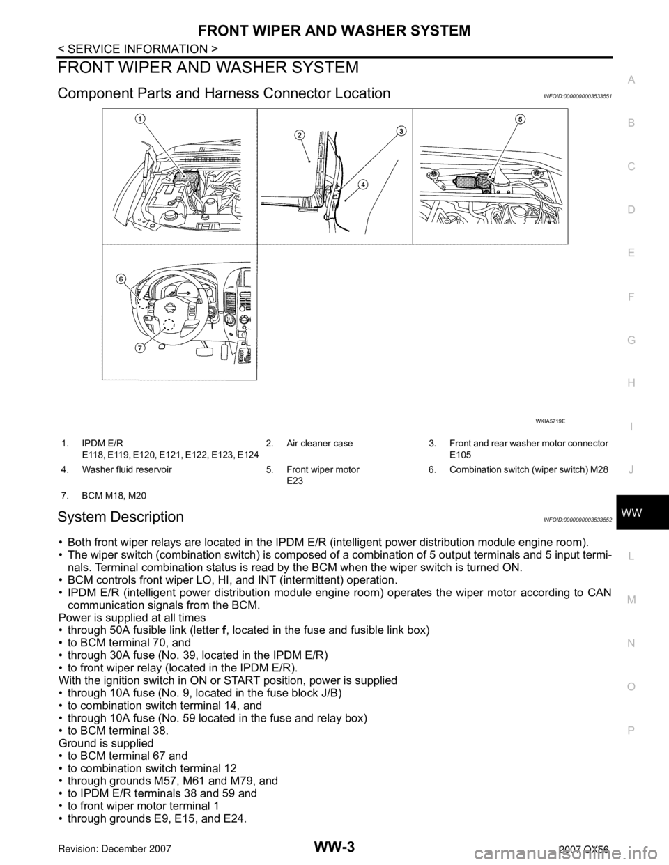
Component Parts and Harness Connector LocationINFOID:0000000003533551
System DescriptionINFOID:0000000003533552
• Both front wiper relays are located in the IPDM E/R (intelligent power distribution module engine room).
• The wiper switch (combination switch) is composed of a combination of 5 output terminals and 5 input termi-
nals. Terminal combination status is read by the BCM when the wiper switch is turned ON.
• BCM controls front wiper LO, HI, and INT (intermittent) operation.
• IPDM E/R (intelligent power distribution module engine room) operates the wiper motor according to CAN
communication signals from the BCM.
Power is supplied at all times
• through 50A fusible link (letter f, located in the fuse and fusible link box)
• to BCM terminal 70, and
• through 30A fuse (No. 39, located in the IPDM E/R)
• to front wiper relay (located in the IPDM E/R).
With the ignition switch in ON or START position, power is supplied
• through 10A fuse (No. 9, located in the fuse block J/B)
• to combination switch terminal 14, and
• through 10A fuse (No. 59 located in the fuse and relay box)
• to BCM terminal 38.
Ground is supplied
• to BCM terminal 67 and
• to combination switch terminal 12
• through grounds M57, M61 and M79, and
• to IPDM E/R terminals 38 and 59 and
• to front wiper motor terminal 1
• through grounds E9, E15, and E24.
WKIA5719E
1. IPDM E/R
E118, E119, E120, E121, E122, E123, E1242. Air cleaner case 3. Front and rear washer motor connector
E105
4. Washer fluid reservoir 5. Front wiper motor
E236. Combination switch (wiper switch) M28
7. BCM M18, M20
Page 3021 of 3061

WW-4
< SERVICE INFORMATION >
FRONT WIPER AND WASHER SYSTEM
LOW SPEED WIPER OPERATION
When the ignition switch is in the ON or START position, and the front wiper switch is turned to the low posi-
tion, the BCM detects a low speed wiper ON request through the combination switch (wiper switch) reading
function. The BCM then sends a front wiper (low) request signal over CAN communication lines
• from BCM terminals 39 and 40
• to IPDM E/R terminals 39 and 40.
When IPDM E/R receives front wiper (low) request signal, it supplies ground to energize the front wiper relay.
With the front wiper relay energized, power is supplied
• through front wiper relay
• to front wiper high relay
• through IPDM E/R terminal 32
• to front wiper motor terminal 3.
With power and ground supplied, the front wiper motor operates at low speed.
HI SPEED WIPER OPERATION
When the ignition switch is in the ON or START position, and the front wiper switch is turned to the high posi-
tion, the BCM detects a high speed wiper ON request through the combination switch (wiper switch) reading
function. The BCM then sends a front wiper (high) request signal over CAN communication lines
• from BCM terminals 39 and 40
• to IPDM E/R terminals 39 and 40.
When the IPDM E/R receives a front wiper (high) request signal, it supplies ground to energize the front wiper
and the front wiper high relays.
With the front wiper and the front wiper high relays energized, power is supplied
• through front wiper relay
• to front wiper high relay
• through IPDM E/R terminal 35
• to front wiper motor terminal 2.
With power and ground supplied, the front wiper motor operates at high speed.
INTERMITTENT OPERATION
Wiper intermittent operation delay interval is determined from the combination of the intermittent wiper dial
position inputs and vehicle speed. During each intermittent operation delay interval, the BCM sends a front
wiper request signal to the IPDM E/R to operate the wipers.
When the ignition switch is in the ON or START position, and the front wiper switch is turned to an intermittent
position, the BCM detects a front wiper (intermittent) ON request through the combination switch (wiper
switch) reading function.
The BCM then sends a front wiper (intermittent) request signal over CAN communication lines
• from BCM terminals 39 and 40
• to IPDM E/R terminals 39 and 40.
When the BCM determines that combination switch status is front wiper intermittent ON, it performs the follow-
ing operations.
• BCM detects ON/OFF status of intermittent wiper dial position.
• BCM calculates operation interval from wiper dial position and vehicle speed signal received through CAN
communications.
• BCM sends front wiper request signal (INT) to IPDM E/R at calculated operation interval.
When the IPDM E/R receives a front wiper request signal (INT), it supplies ground to energize the front wiper
relay. It then sends an auto-stop signal to the BCM, and conducts intermittent front wiper motor operation.
AUTO STOP OPERATION
When the wiper arms are not located at the base of the windshield, and the wiper switch is turned OFF, the
wiper motor will continue to operate until the wiper arms reach the windshield base. When the wiper arms
reach the base of windshield, front wiper motor terminals 6 and 1 are connected.
Ground is supplied
• to IPDM E/R terminal 43
• through front wiper motor terminal 6
• through front wiper motor terminal 1
• through grounds E9, E15, and E24.
The IPDM E/R sends an auto stop operation signal to the BCM through CAN communication lines.
When the BCM receives an auto stop operation signal, the BCM sends wiper stop signal to the IPDM E/R over
CAN communication lines. The IPDM E/R then de-energizes the front wiper relay.
The wiper motor will then stop the wiper arms at the STOP position.
Page 3027 of 3061
WW-10
< SERVICE INFORMATION >
FRONT WIPER AND WASHER SYSTEM
Work Flow
INFOID:0000000003533558
1. Confirm the trouble symptom or customer complaint.
2. Understand the system description, refer to WW-3, "
System Description".
3. Perform preliminary inspection, refer to WW-10, "
Preliminary Check".
4. Check symptom and repair or replace the cause of malfunction.
5. Does wiper function operate normally? If it operates normally, GO TO 6. If not, GO TO 4.
6. Inspection End.
Preliminary CheckINFOID:0000000003533559
INSPECTION FOR POWER SUPPLY AND GROUND CIRCUIT
Inspection procedure
1.CHECK FUSE
Check if wiper or washer fuse is blown.
OK or NG
OK >> GO TO 2.
NG >> If fuse is blown, be sure to eliminate cause of blown fuse before installing new fuse.
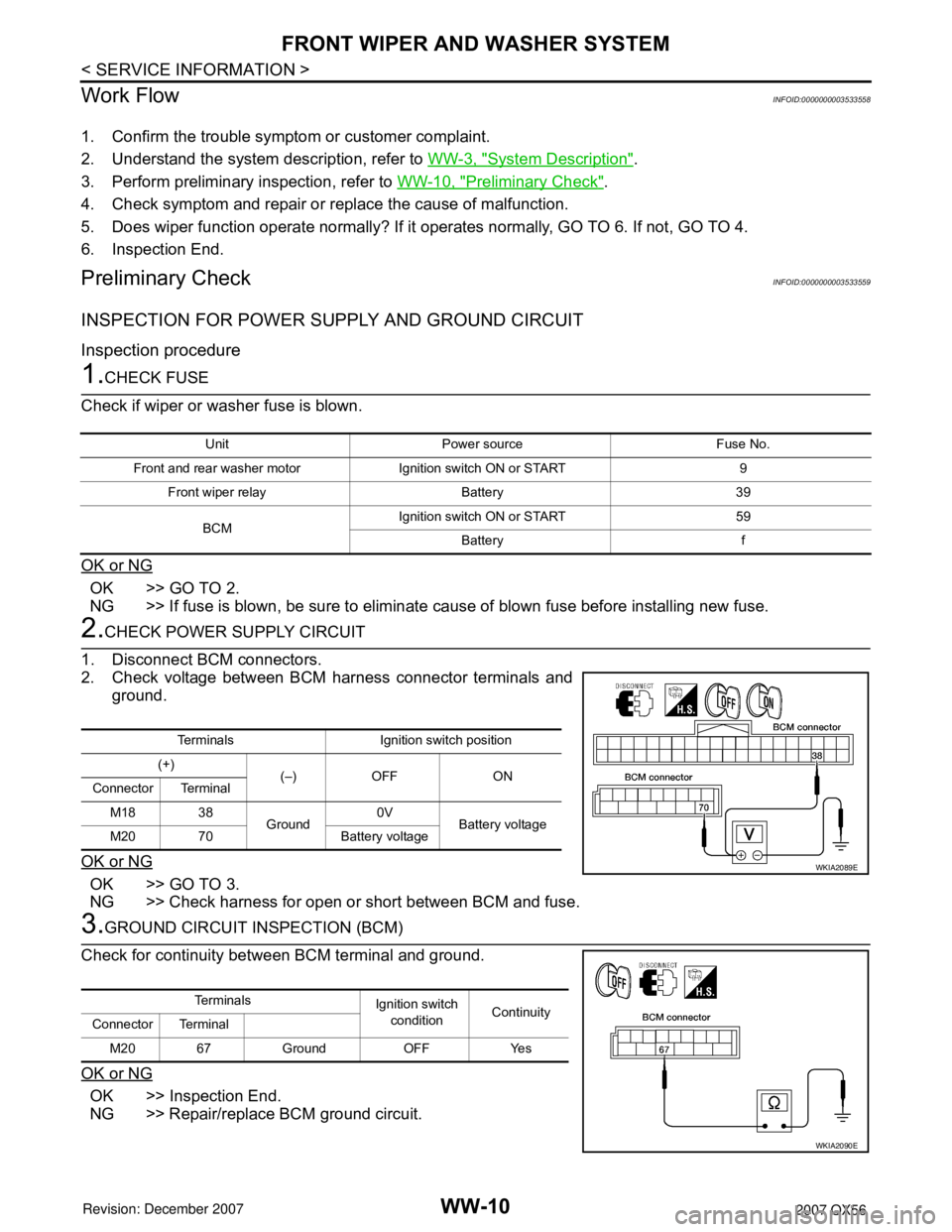
2.CHECK POWER SUPPLY CIRCUIT
1. Disconnect BCM connectors.
2. Check voltage between BCM harness connector terminals and
ground.
OK or NG
OK >> GO TO 3.
NG >> Check harness for open or short between BCM and fuse.
3.GROUND CIRCUIT INSPECTION (BCM)
Check for continuity between BCM terminal and ground.
OK or NG
OK >> Inspection End.
NG >> Repair/replace BCM ground circuit.
Unit Power source Fuse No.
Front and rear washer motor Ignition switch ON or START 9
Front wiper relay Battery 39
BCMIgnition switch ON or START 59
Battery f
Terminals Ignition switch position
(+)
(–) OFF ON
Connector Terminal
M18 38
Ground0V
Battery voltage
M20 70 Battery voltage
WKIA2089E
Te r m i n a l s
Ignition switch
conditionContinuity
Connector Terminal
M20 67 Ground OFF Yes
WKIA2090E
Page 3030 of 3061
FRONT WIPER AND WASHER SYSTEM
WW-13
< SERVICE INFORMATION >
C
D
E
F
G
H
I
J
L
MA
B
WW
N
O
P
Front Wiper Does Not OperateINFOID:0000000003533562
CAUTION:
During IPDM E/R fail-safe control, front wipers may not operate. Refer to PG-17, "
System Description"
to make sure that it is not in fail-safe status.
Inspection Procedure
1.CHECK IPDM E/R TO FRONT WIPERS
With CONSULT-II
1. Select "IPDM E/R" with CONSULT-II, and select "ACTIVE
TEST" on "SELECT DIAG MODE" screen.
2. Select "FRONT WIPER" on "SELECT TEST ITEM" screen.
Without CONSULT-II
1. Turn on front wipers using auto active test. Refer to PG-20,
"Auto Active Test".
2. Confirm front wiper operation.
OK or NG
OK >> GO TO 4.
NG >> GO TO 2.
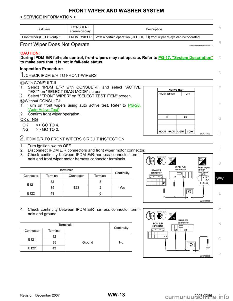
2.IPDM E/R TO FRONT WIPERS CIRCUIT INSPECTION
1. Turn ignition switch OFF.
2. Disconnect IPDM E/R connectors and front wiper motor connector.
3. Check continuity between IPDM E/R harness connector termi-
nals and front wiper motor harness connector terminals.
4. Check continuity between IPDM E/R harness connector termi-
nals and ground.
Te s t i t e mCONSULT-II
screen displayDescription
Front wiper (HI, LO) output FRONT WIPER With a certain operation (OFF, HI, LO) front wiper relays can be operated.
SKIA3486E
Te r m i n a l s
Continuity
Connector Terminal Connector Terminal
E12132
E233
Ye s 35 2
E122 43 6
WKIA2082E
Te r m i n a l s
Continuity
Connector Terminal
E12132
Ground No 35
E122 43
WKIA2099E
Page 3031 of 3061
WW-14
< SERVICE INFORMATION >
FRONT WIPER AND WASHER SYSTEM
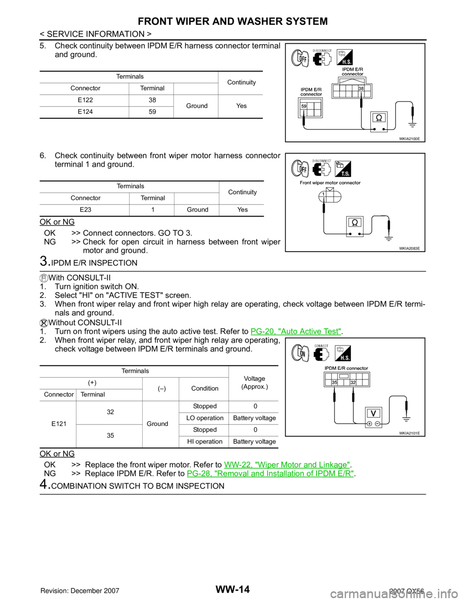
5. Check continuity between IPDM E/R harness connector terminal
and ground.
6. Check continuity between front wiper motor harness connector
terminal 1 and ground.
OK or NG
OK >> Connect connectors. GO TO 3.
NG >> Check for open circuit in harness between front wiper
motor and ground.
3.IPDM E/R INSPECTION
With CONSULT-II
1. Turn ignition switch ON.
2. Select "HI" on "ACTIVE TEST" screen.
3. When front wiper relay and front wiper high relay are operating, check voltage between IPDM E/R termi-
nals and ground.
Without CONSULT-II
1. Turn on front wipers using the auto active test. Refer to PG-20, "
Auto Active Test".
2. When front wiper relay, and front wiper high relay are operating,
check voltage between IPDM E/R terminals and ground.
OK or NG
OK >> Replace the front wiper motor. Refer to WW-22, "Wiper Motor and Linkage".
NG >> Replace IPDM E/R. Refer to PG-28, "
Removal and Installation of IPDM E/R".
4.COMBINATION SWITCH TO BCM INSPECTION
Te r m i n a l s
Continuity
Connector Terminal
E122 38
Ground Yes
E124 59
WKIA2100E
Te r m i n a l s
Continuity
Connector Terminal
E23 1 Ground Yes
WKIA2083E
Te r m i n a l s
Vol tag e
(Approx.) (+)
(–) Condition
Connector Terminal
E12132
GroundStopped 0
LO operation Battery voltage
35Stopped 0
HI operation Battery voltage
WKIA2101E
Page 3034 of 3061
FRONT WIPER AND WASHER SYSTEM
WW-17
< SERVICE INFORMATION >
C
D
E
F
G
H
I
J
L
MA
B
WW
N
O
P
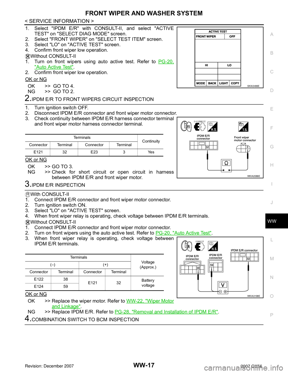
1. Select "IPDM E/R" with CONSULT-II, and select "ACTIVE
TEST" on "SELECT DIAG MODE" screen.
2. Select "FRONT WIPER" on "SELECT TEST ITEM" screen.
3. Select "LO" on "ACTIVE TEST" screen.
4. Confirm front wiper low operation.
Without CONSULT-II
1. Turn on front wipers using auto active test. Refer to PG-20,
"Auto Active Test".
2. Confirm front wiper low operation.
OK or NG
OK >> GO TO 4.
NG >> GO TO 2.
2.IPDM E/R TO FRONT WIPERS CIRCUIT INSPECTION
1. Turn ignition switch OFF.
2. Disconnect IPDM E/R connector and front wiper motor connector.
3. Check continuity between IPDM E/R harness connector terminal
and front wiper motor harness connector terminal.
OK or NG
OK >> GO TO 3.
NG >> Check for short circuit or open circuit in harness
between IPDM E/R and front wiper motor.
3.IPDM E/R INSPECTION
With CONSULT-II
1. Connect IPDM E/R connector and front wiper motor connector.
2. Turn ignition switch ON.
3. Select "LO" on "ACTIVE TEST" screen.
4. When front wiper relay is operating, check voltage between IPDM E/R terminals.
Without CONSULT-II
1. Connect IPDM E/R connector and front wiper motor connector.
2. Turn on front wipers using the auto active test. Refer to PG-20, "
Auto Active Test".
3. When front wiper relay is operating, check voltage between
IPDM E/R terminals.
OK or NG
OK >> Replace the wiper motor. Refer to WW-22, "Wiper Motor
and Linkage".
NG >> Replace IPDM E/R. Refer to PG-28, "
Removal and Installation of IPDM E/R".
4.COMBINATION SWITCH TO BCM INSPECTION
SKIA3486E
Te r m i n a l s
Continuity
Connector Terminal Connector Terminal
E121 32 E23 3 Yes
WKIA2086E
Te r m i n a l s
Vo l ta g e
(Approx.) (–) (+)
Connector Terminal Connector Terminal
E122 38
E121 32Battery
voltage
E124 59
WKIA3198E
Page 3035 of 3061
WW-18
< SERVICE INFORMATION >
FRONT WIPER AND WASHER SYSTEM
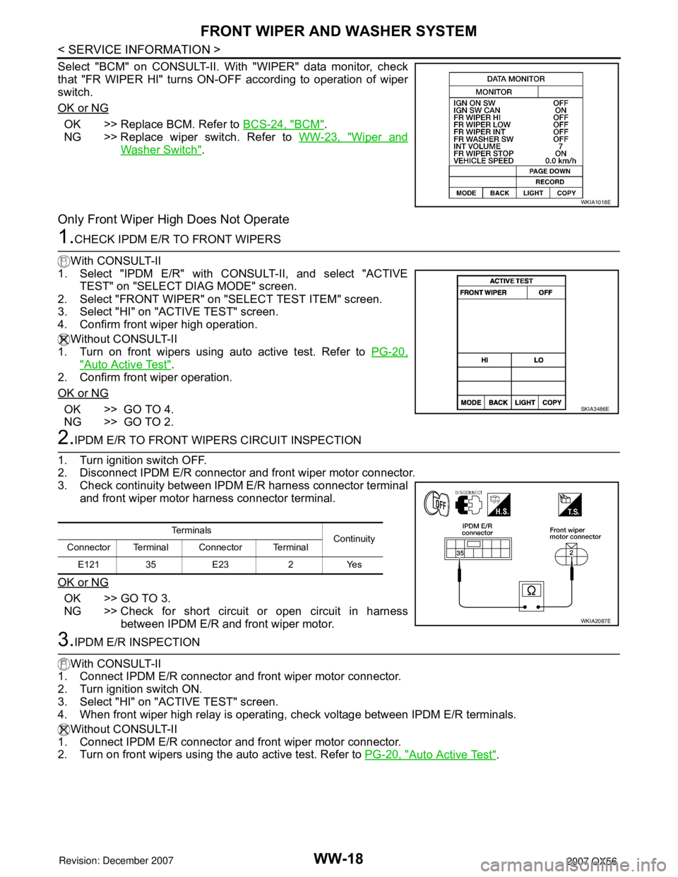
Select "BCM" on CONSULT-II. With "WIPER" data monitor, check
that "FR WIPER HI" turns ON-OFF according to operation of wiper
switch.
OK or NG
OK >> Replace BCM. Refer to BCS-24, "BCM".
NG >> Replace wiper switch. Refer to WW-23, "
Wiper and
Washer Switch".
Only Front Wiper High Does Not Operate
1.CHECK IPDM E/R TO FRONT WIPERS
With CONSULT-II
1. Select "IPDM E/R" with CONSULT-II, and select "ACTIVE
TEST" on "SELECT DIAG MODE" screen.
2. Select "FRONT WIPER" on "SELECT TEST ITEM" screen.
3. Select "HI" on "ACTIVE TEST" screen.
4. Confirm front wiper high operation.
Without CONSULT-II
1. Turn on front wipers using auto active test. Refer to PG-20,
"Auto Active Test".
2. Confirm front wiper operation.
OK or NG
OK >> GO TO 4.
NG >> GO TO 2.
2.IPDM E/R TO FRONT WIPERS CIRCUIT INSPECTION
1. Turn ignition switch OFF.
2. Disconnect IPDM E/R connector and front wiper motor connector.
3. Check continuity between IPDM E/R harness connector terminal
and front wiper motor harness connector terminal.
OK or NG
OK >> GO TO 3.
NG >> Check for short circuit or open circuit in harness
between IPDM E/R and front wiper motor.
3.IPDM E/R INSPECTION
With CONSULT-II
1. Connect IPDM E/R connector and front wiper motor connector.
2. Turn ignition switch ON.
3. Select "HI" on "ACTIVE TEST" screen.
4. When front wiper high relay is operating, check voltage between IPDM E/R terminals.
Without CONSULT-II
1. Connect IPDM E/R connector and front wiper motor connector.
2. Turn on front wipers using the auto active test. Refer to PG-20, "
Auto Active Test".
WKIA1018E
SKIA3486E
Te r m i n a l s
Continuity
Connector Terminal Connector Terminal
E121 35 E23 2 Yes
WKIA2087E
Page 3036 of 3061
FRONT WIPER AND WASHER SYSTEM
WW-19
< SERVICE INFORMATION >
C
D
E
F
G
H
I
J
L
MA
B
WW
N
O
P
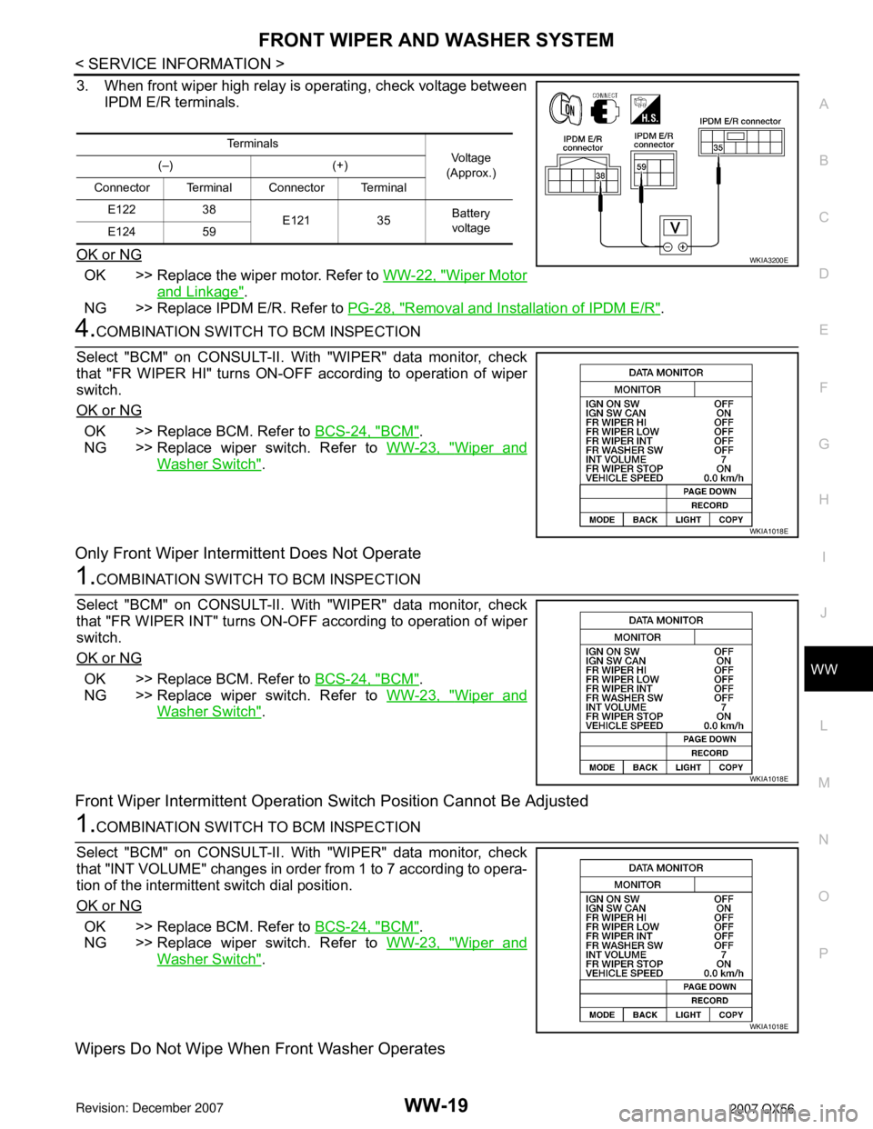
3. When front wiper high relay is operating, check voltage between
IPDM E/R terminals.
OK or NG
OK >> Replace the wiper motor. Refer to WW-22, "Wiper Motor
and Linkage".
NG >> Replace IPDM E/R. Refer to PG-28, "
Removal and Installation of IPDM E/R".
4.COMBINATION SWITCH TO BCM INSPECTION
Select "BCM" on CONSULT-II. With "WIPER" data monitor, check
that "FR WIPER HI" turns ON-OFF according to operation of wiper
switch.
OK or NG
OK >> Replace BCM. Refer to BCS-24, "BCM".
NG >> Replace wiper switch. Refer to WW-23, "
Wiper and
Washer Switch".
Only Front Wiper Intermittent Does Not Operate
1.COMBINATION SWITCH TO BCM INSPECTION
Select "BCM" on CONSULT-II. With "WIPER" data monitor, check
that "FR WIPER INT" turns ON-OFF according to operation of wiper
switch.
OK or NG
OK >> Replace BCM. Refer to BCS-24, "BCM".
NG >> Replace wiper switch. Refer to WW-23, "
Wiper and
Washer Switch".
Front Wiper Intermittent Operation Switch Position Cannot Be Adjusted
1.COMBINATION SWITCH TO BCM INSPECTION
Select "BCM" on CONSULT-II. With "WIPER" data monitor, check
that "INT VOLUME" changes in order from 1 to 7 according to opera-
tion of the intermittent switch dial position.
OK or NG
OK >> Replace BCM. Refer to BCS-24, "BCM".
NG >> Replace wiper switch. Refer to WW-23, "
Wiper and
Washer Switch".
Wipers Do Not Wipe When Front Washer Operates
Te r m i n a l s
Vo l ta g e
(Approx.) (–) (+)
Connector Terminal Connector Terminal
E122 38
E121 35Battery
voltage
E124 59
WKIA3200E
WKIA1018E
WKIA1018E
WKIA1018E