2007 INFINITI QX56 battery
[x] Cancel search: batteryPage 1201 of 3061
![INFINITI QX56 2007 Factory Service Manual EC-118
< SERVICE INFORMATION >
TROUBLE DIAGNOSIS
A/F S1 HTR (B1)
[%]• A/F sensor 1 heater control value com-
puted by ECM according to the input sig-
nals.
• The current flow to the heater become INFINITI QX56 2007 Factory Service Manual EC-118
< SERVICE INFORMATION >
TROUBLE DIAGNOSIS
A/F S1 HTR (B1)
[%]• A/F sensor 1 heater control value com-
puted by ECM according to the input sig-
nals.
• The current flow to the heater become](/manual-img/42/57029/w960_57029-1200.png)
EC-118
< SERVICE INFORMATION >
TROUBLE DIAGNOSIS
A/F S1 HTR (B1)
[%]• A/F sensor 1 heater control value com-
puted by ECM according to the input sig-
nals.
• The current flow to the heater becomes
larger as the value increases. A/F S1 HTR (B2)
[%]
AC PRESS SEN [V]• The signal voltage from the refrigerant
pressure sensor is displayed.
VHCL SPEED SE
[km/h] or [mph]• The vehicle speed computed from the
vehicle speed signal sent from combina-
tion meter is displayed.
SET VHCL SPD
[km/h] or [mph]• The preset vehicle speed is displayed.
MAIN SW
[ON/OFF]• Indicates [ON/OFF] condition from MAIN
switch signal.
CANCEL SW
[ON/OFF]• Indicates [ON/OFF] condition from CAN-
CEL switch signal.
RESUME/ACC SW
[ON/OFF]• Indicates [ON/OFF] condition from RE-
SUME/ACCELERATE switch signal.
SET SW
[ON/OFF]• Indicates [ON/OFF] condition from SET/
COAST switch signal.
BRAKE SW1
[ON/OFF]• Indicates [ON/OFF] condition from
ASCD brake switch signal.
BRAKE SW2
[ON/OFF]• Indicates [ON/OFF] condition of stop
lamp switch signal.
DIST SW
[ON/OFF]• Indicates [ON/OFF] condition from DIS-
TANCE switch signal.
VHCL SPD CUT
[NON/CUT]• Indicates the vehicle cruise condition.
NON: Vehicle speed is maintained at the
ASCD set speed.
CUT: Vehicle speed increased to exces-
sively high compared with the ASCD set
speed, and ASCD operation is cut off.
LO SPEED CUT
[NON/CUT]• Indicates the vehicle cruise condition.
NON: Vehicle speed is maintained at the
ASCD set speed.
CUT: Vehicle speed decreased to exces-
sively low compared with the ASCD set
speed, and ASCD operation is cut off.
AT O D M O N I T O R
[ON/OFF]• Indicates [ON/OFF] condition of A/T O/D
according to the input signal from the
TCM.
AT O D C A N C E L
[ON/OFF]• Indicates [ON/OFF] condition of A/T O/D
cancel signal sent from the TCM.
CRUISE LAMP
[ON/OFF]• Indicates [ON/OFF] condition of CRUISE
lamp determined by the ECM according
to the input signals.
SET LAMP
[ON/OFF]• Indicates [ON/OFF] condition of SET
lamp determined by the ECM according
to the input signals.
ALT DUTY [%]• Indicates the duty ratio of the power gen-
eration command value. The ratio is cal-
culated by ECM based on the battery
current sensor signal.
BAT CUR SEN [mV]• The signal voltage of battery current sen-
sor is displayed. Monitored item
[Unit]ECM IN-
PUT SIG-
NALSMAIN
SIGNALSDescription Remarks
Page 1203 of 3061

EC-120
< SERVICE INFORMATION >
TROUBLE DIAGNOSIS
*: Leaving cooling fan OFF with CONSULT-II while engine is running may cause the engine to overheat.
DTC & SRT CONFIRMATION MODE
SRT STATUS Mode
For details, refer to EC-49, "Emission-related Diagnostic Information".
SRT WORK SUPPORT Mode
This mode enables a technician to drive a vehicle to set the SRT while monitoring the SRT status.
DTC WORK SUPPORT Mode
TEST ITEM CONDITION JUDGEMENT CHECK ITEM (REMEDY)
FUEL INJEC-
TION• Engine: Return to the original
trouble condition
• Change the amount of fuel injec-
tion using CONSULT-II.If trouble symptom disappears, see
CHECK ITEM.• Harness and connectors
• Fuel injector
• Air fuel ratio (A/F) sensor 1
IGNITION TIM-
ING• Engine: Return to the original
trouble condition
• Timing light: Set
• Retard the ignition timing using
CONSULT-II.If trouble symptom disappears, see
CHECK ITEM.• Perform Idle Air Volume Learning.
POWER BAL-
ANCE• Engine: After warming up, idle the
engine.
• A/C switch: OFF
• Selector lever: P or N
• Cut off each injector signal one at
a time using CONSULT-II.Engine runs rough or dies.• Harness and connectors
• Compression
• Fuel injector
• Power transistor
•Spark plug
• Ignition coil
COOLING FAN*• Ignition switch: ON
• Turn the cooling fan HI and OFF
using CONSULT-II.Cooling fan moves and stops.• Harness and connectors
• Cooling fan motor
• IPDM E/R
ENG COOLANT
TEMP• Engine: Return to the original
trouble condition
• Change the engine coolant tem-
perature using CONSULT-II.If trouble symptom disappears, see
CHECK ITEM.• Harness and connectors
• Engine coolant temperature sen-
sor
• Fuel injector
FUEL PUMP RE-
LAY• Ignition switch: ON
(Engine stopped)
• Turn the fuel pump relay ON and
OFF using CONSULT-II and lis-
ten to operating sound.Fuel pump relay makes the operat-
ing sound.• Harness and connectors
•Fuel pump relay
PURG VOL
CONT/V• Engine: After warming up, run en-
gine at 1,500 rpm.
• Change the EVAP canister purge
volume control solenoid valve
opening percent using CON-
SULT-II.Engine speed changes according to
the opening percent.• Harness and connectors
• Solenoid valve
FUEL/T TEMP
SEN• Change the fuel tank temperature using CONSULT-II.
VENT CON-
TROL/V• Ignition switch: ON
(Engine stopped)
• Turn solenoid valve ON and OFF
with the CONSULT-II and listen to
operating sound.Solenoid valve makes an operating
sound.• Harness and connectors
• Solenoid valve
V/T ASSIGN AN-
GLE• Engine: Return to the original
trouble condition
• Change intake valve timing using
CONSULT-II.If trouble symptom disappears, see
CHECK ITEM.• Harness and connectors
• Intake valve timing control sole-
noid valve
ALTERNATOR
DUTY•Engine: Idle
• Change duty ratio using CON-
SULT-II.Battery voltage changes.• Harness and connectors
• IPDM E/R
•Alternator
Page 1206 of 3061
TROUBLE DIAGNOSIS
EC-123
< SERVICE INFORMATION >
C
D
E
F
G
H
I
J
K
L
MA
EC
N
P O
INSPECTION PROCEDURE
1. Turn ignition switch OFF.
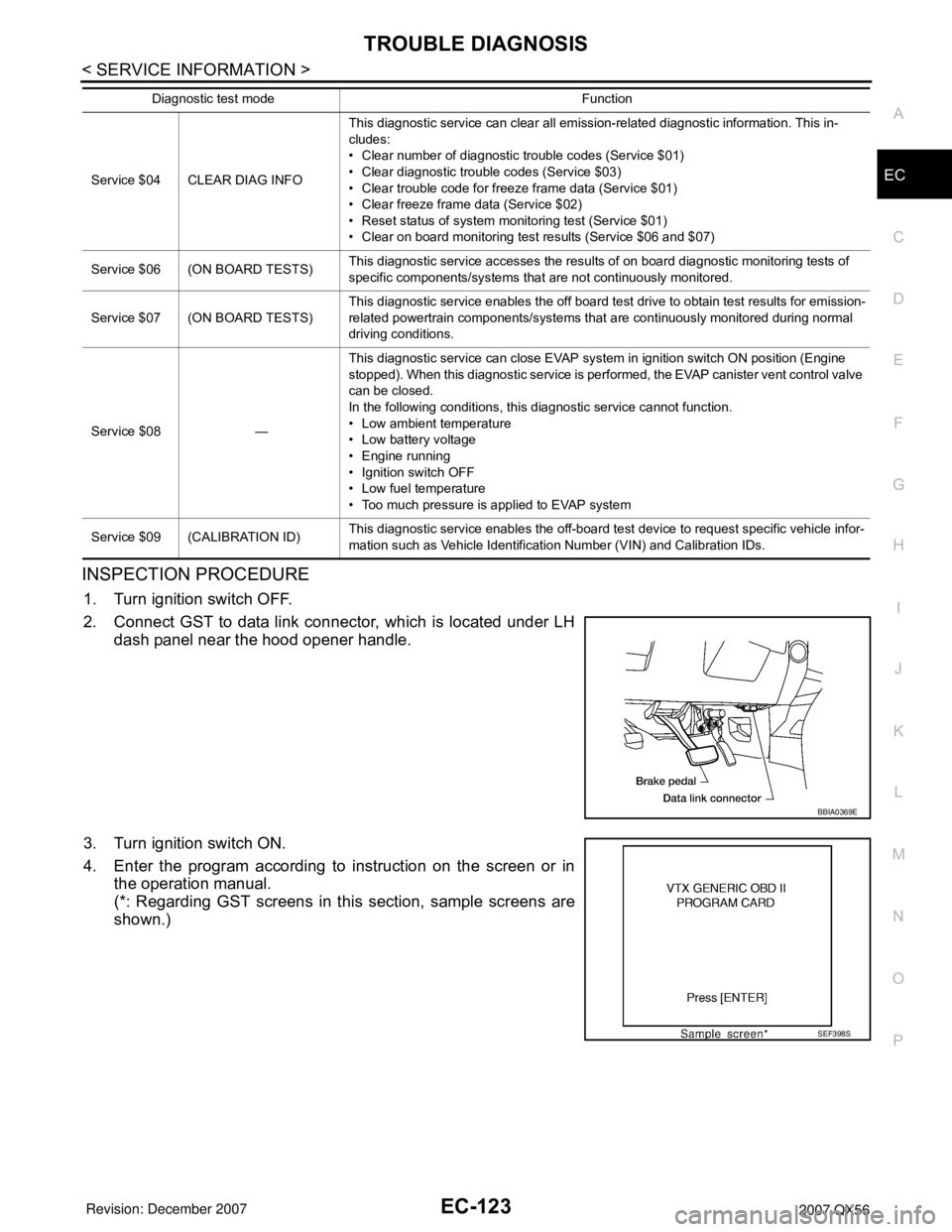
2. Connect GST to data link connector, which is located under LH
dash panel near the hood opener handle.
3. Turn ignition switch ON.
4. Enter the program according to instruction on the screen or in
the operation manual.
(*: Regarding GST screens in this section, sample screens are
shown.)
Service $04 CLEAR DIAG INFOThis diagnostic service can clear all emission-related diagnostic information. This in-
cludes:
• Clear number of diagnostic trouble codes (Service $01)
• Clear diagnostic trouble codes (Service $03)
• Clear trouble code for freeze frame data (Service $01)
• Clear freeze frame data (Service $02)
• Reset status of system monitoring test (Service $01)
• Clear on board monitoring test results (Service $06 and $07)
Service $06 (ON BOARD TESTS)This diagnostic service accesses the results of on board diagnostic monitoring tests of
specific components/systems that are not continuously monitored.
Service $07 (ON BOARD TESTS)This diagnostic service enables the off board test drive to obtain test results for emission-
related powertrain components/systems that are continuously monitored during normal
driving conditions.
Service $08 —This diagnostic service can close EVAP system in ignition switch ON position (Engine
stopped). When this diagnostic service is performed, the EVAP canister vent control valve
can be closed.
In the following conditions, this diagnostic service cannot function.
• Low ambient temperature
• Low battery voltage
• Engine running
• Ignition switch OFF
• Low fuel temperature
• Too much pressure is applied to EVAP system
Service $09 (CALIBRATION ID)This diagnostic service enables the off-board test device to request specific vehicle infor-
mation such as Vehicle Identification Number (VIN) and Calibration IDs. Diagnostic test mode Function
BBIA0369E
SEF398S
Page 1207 of 3061
EC-124
< SERVICE INFORMATION >
TROUBLE DIAGNOSIS
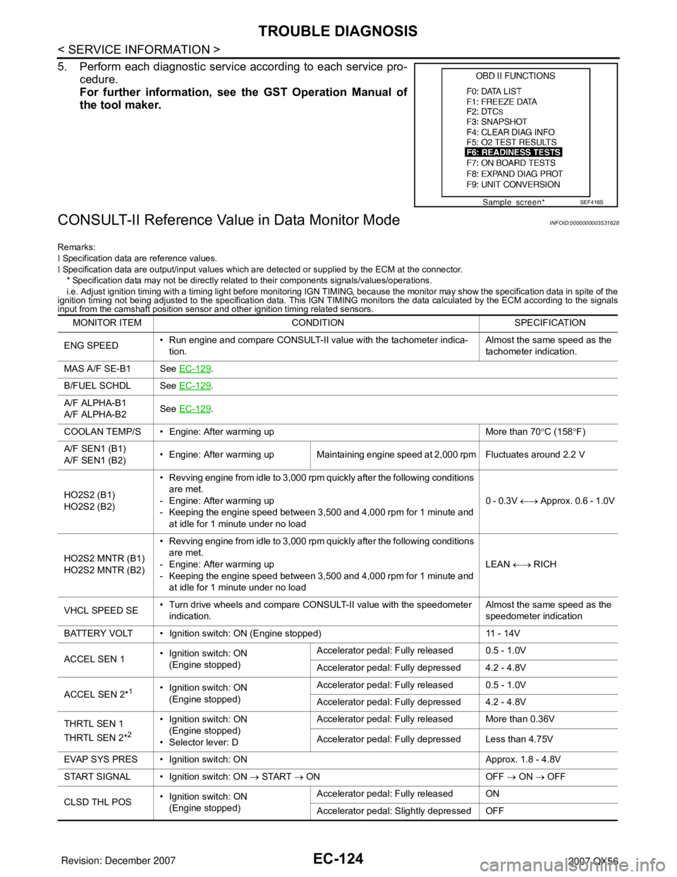
5. Perform each diagnostic service according to each service pro-
cedure.
For further information, see the GST Operation Manual of
the tool maker.
CONSULT-II Reference Value in Data Monitor ModeINFOID:0000000003531628
Remarks:
l Specification data are reference values.
l Specification data are output/input values which are detected or supplied by the ECM at the connector.
* Specification data may not be directly related to their components signals/values/operations.
i.e. Adjust ignition timing with a timing light before monitoring IGN TIMING, because the monitor may show the specification data in spite of the
ignition timing not being adjusted to the specification data. This IGN TIMING monitors the data calculated by the ECM according to the signals
input from the camshaft position sensor and other ignition timing related sensors.
SEF416S
MONITOR ITEM CONDITION SPECIFICATION
ENG SPEED• Run engine and compare CONSULT-II value with the tachometer indica-
tion.Almost the same speed as the
tachometer indication.
MAS A/F SE-B1 See EC-129
.
B/FUEL SCHDL See EC-129
.
A/F ALPHA-B1
A/F ALPHA-B2See EC-129
.
COOLAN TEMP/S • Engine: After warming up More than 70°C (158°F)
A/F SEN1 (B1)
A/F SEN1 (B2)• Engine: After warming up Maintaining engine speed at 2,000 rpm Fluctuates around 2.2 V
HO2S2 (B1)
HO2S2 (B2)• Revving engine from idle to 3,000 rpm quickly after the following conditions
are met.
- Engine: After warming up
- Keeping the engine speed between 3,500 and 4,000 rpm for 1 minute and
at idle for 1 minute under no load0 - 0.3V ←→ Approx. 0.6 - 1.0V
HO2S2 MNTR (B1)
HO2S2 MNTR (B2)• Revving engine from idle to 3,000 rpm quickly after the following conditions
are met.
- Engine: After warming up
- Keeping the engine speed between 3,500 and 4,000 rpm for 1 minute and
at idle for 1 minute under no loadLEAN ←→ RICH
VHCL SPEED SE• Turn drive wheels and compare CONSULT-II value with the speedometer
indication.Almost the same speed as the
speedometer indication
BATTERY VOLT • Ignition switch: ON (Engine stopped) 11 - 14V
ACCEL SEN 1• Ignition switch: ON
(Engine stopped)Accelerator pedal: Fully released 0.5 - 1.0V
Accelerator pedal: Fully depressed 4.2 - 4.8V
ACCEL SEN 2*
1• Ignition switch: ON
(Engine stopped)Accelerator pedal: Fully released 0.5 - 1.0V
Accelerator pedal: Fully depressed 4.2 - 4.8V
THRTL SEN 1
THRTL SEN 2*
2
• Ignition switch: ON
(Engine stopped)
• Selector lever: DAccelerator pedal: Fully released More than 0.36V
Accelerator pedal: Fully depressed Less than 4.75V
EVAP SYS PRES • Ignition switch: ON Approx. 1.8 - 4.8V
START SIGNAL • Ignition switch: ON → START → ON OFF → ON → OFF
CLSD THL POS• Ignition switch: ON
(Engine stopped)Accelerator pedal: Fully released ON
Accelerator pedal: Slightly depressed OFF
Page 1209 of 3061

EC-126
< SERVICE INFORMATION >
TROUBLE DIAGNOSIS
COOLING FAN• Engine: After warming up, idle the
engine
• Air conditioner switch: OFFEngine coolant temperature: 99°C
(210°F) or lessOFF
Engine coolant temperature: 100°C
(212°F) or moreHI
HO2S2 HTR (B1)
HO2S2 HTR (B2)• Engine speed: Below 3,600 rpm after the following conditions are met.
- Engine: After warming up
- Keeping the engine speed between 3,500 and 4,000 rpm for 1 minute and
at idle for 1 minute under no loadON
• Engine speed: Above 3,600 rpm OFF
I/P PULLY SPD • Vehicle speed: More than 20 km/h (12 MPH)Almost the same speed as the
tachometer indication
VEHICLE SPEED• Turn drive wheels and compare CONSULT-II value with the speedometer
indication.Almost the same speed as the
speedometer indication
TRVL AFTER MIL • Ignition switch: ONVehicle has traveled after MIL has
turned ON.0 - 65,535 km
(0 - 40,723 mile)
A/F S1 HTR (B1)
A/F S1 HTR (B2)• Engine: After warming up, idle the engine 4 - 100%
AC PRESS SEN• Engine: Idle
• Both A/C switch and blower fan switch: ON (Compressor operates.)1.0 - 4.0V
VHCL SPEED SE• Turn drive wheels and compare CONSULT-II value with the speedometer
indication.Almost the same speed as the
speedometer indication
SET VHCL SPD • Engine: Running ASCD: Operating.The preset vehicle speed is dis-
played.
MAIN SW • Ignition switch: ONMAIN switch: Pressed ON
MAIN switch: Released OFF
CANCEL SW • Ignition switch: ONCANCEL switch: Pressed ON
CANCEL switch: Released OFF
RESUME/ACC SW • Ignition switch: ONRESUME/ACCELERATE switch:
PressedON
RESUME/ACCELERATE switch: Re-
leasedOFF
SET SW • Ignition switch: ONSET/COAST switch: Pressed ON
SET/COAST switch: Released OFF
DIST SW • Ignition switch: ONDISTANCE switch: Pressed ON
DISTANCE switch: Released OFF
BRAKE SW1 • Ignition switch: ONBrake pedal: Fully released ON
Brake pedal: Slightly depressed OFF
BRAKE SW2 • Ignition switch: ONBrake pedal: Fully released OFF
Brake pedal: Slightly depressed ON
CRUISE LAMP • Ignition switch: ONMAIN switch: Pressed at the 1st time
→ at the 2nd timeON → OFF
SET LAMP• MAIN switch: ON
• Vehicle speed: Between 40 km/h
(25 MPH) and 144 km/h (89
MPH)ASCD: Operating ON
ASCD: Not operating OFF
ALT DUTY • Engine: Idle 0 - 80%
BAT CUR SEN• Engine speed: Idle
• Battery: Fully charged*
2
• Selector lever: P or N
• Air conditioner switch: OFF
•No loadApprox. 2,600 - 3,500mV MONITOR ITEM CONDITION SPECIFICATION
Page 1210 of 3061
TROUBLE DIAGNOSIS
EC-127
< SERVICE INFORMATION >
C
D
E
F
G
H
I
J
K
L
MA
EC
N
P O*1: Accelerator pedal position sensor 2 signal and throttle position sensor 2 signal are converted by ECM internally. Thus, they differ
from ECM terminals voltage signal.
*2: Before measuring the terminal voltage, confirm the battery is fully charged. Refer to SC-4
.
Major Sensor Reference Graph in Data Monitor ModeINFOID:0000000003531629
The following are the major sensor reference graphs in “DATA MONITOR” mode.
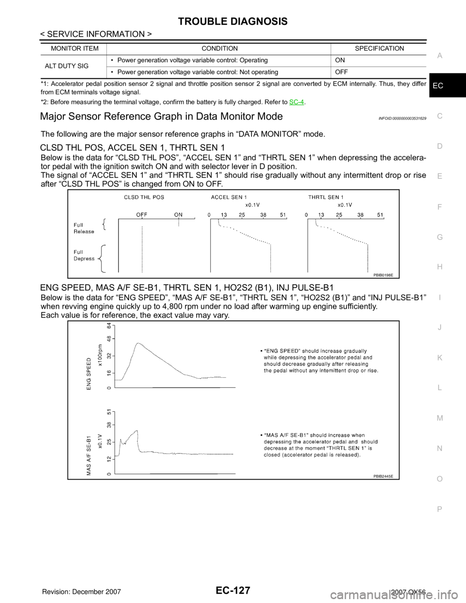
CLSD THL POS, ACCEL SEN 1, THRTL SEN 1
Below is the data for “CLSD THL POS”, “ACCEL SEN 1” and “THRTL SEN 1” when depressing the accelera-
tor pedal with the ignition switch ON and with selector lever in D position.
The signal of “ACCEL SEN 1” and “THRTL SEN 1” should rise gradually without any intermittent drop or rise
after “CLSD THL POS” is changed from ON to OFF.
ENG SPEED, MAS A/F SE-B1, THRTL SEN 1, HO2S2 (B1), INJ PULSE-B1
Below is the data for “ENG SPEED”, “MAS A/F SE-B1”, “THRTL SEN 1”, “HO2S2 (B1)” and “INJ PULSE-B1”
when revving engine quickly up to 4,800 rpm under no load after warming up engine sufficiently.
Each value is for reference, the exact value may vary.
ALT DUTY SIG• Power generation voltage variable control: Operating ON
• Power generation voltage variable control: Not operating OFF MONITOR ITEM CONDITION SPECIFICATION
PBIB0198E
PBIB2445E
Page 1223 of 3061
EC-140
< SERVICE INFORMATION >
POWER SUPPLY AND GROUND CIRCUIT
Diagnosis Procedure
INFOID:0000000003531637
1.INSPECTION START
Start engine.
Is engine running?
Ye s o r N o
Ye s > > G O T O 8 .
No >> GO TO 2.
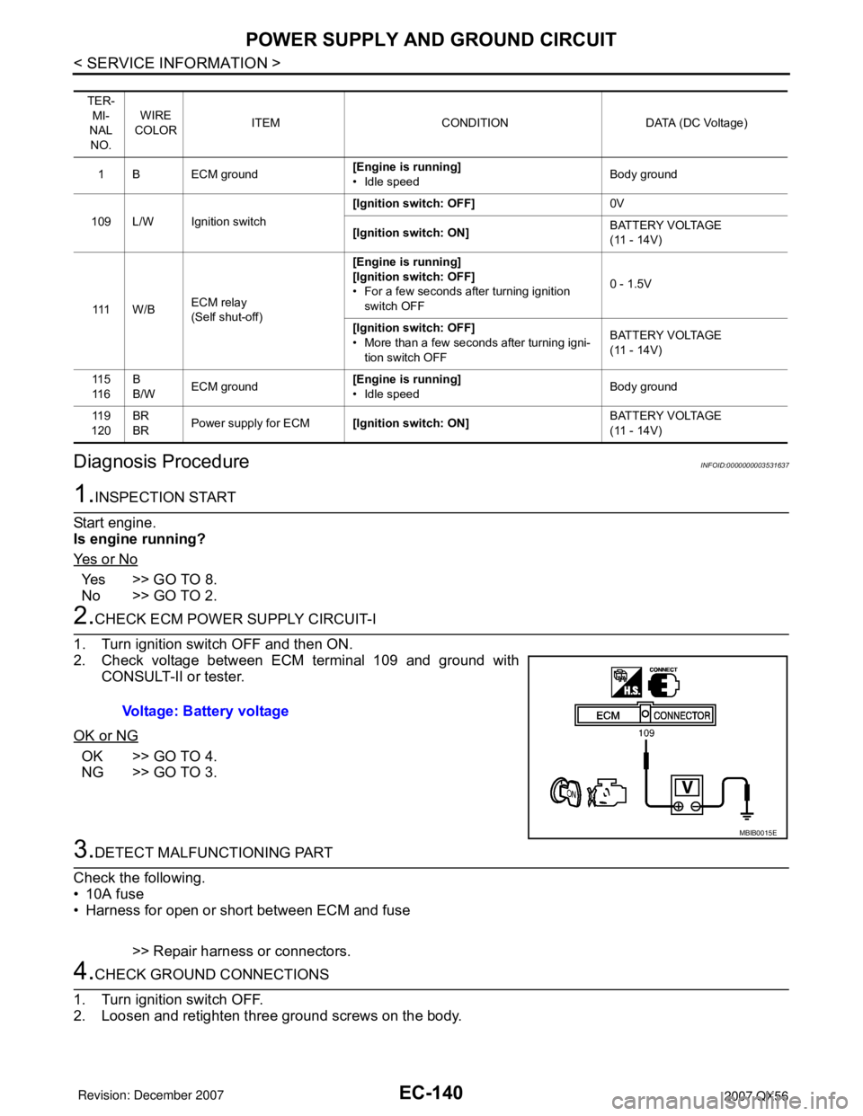
2.CHECK ECM POWER SUPPLY CIRCUIT-I
1. Turn ignition switch OFF and then ON.
2. Check voltage between ECM terminal 109 and ground with
CONSULT-II or tester.
OK or NG
OK >> GO TO 4.
NG >> GO TO 3.
3.DETECT MALFUNCTIONING PART
Check the following.
• 10A fuse
• Harness for open or short between ECM and fuse
>> Repair harness or connectors.
4.CHECK GROUND CONNECTIONS
1. Turn ignition switch OFF.
2. Loosen and retighten three ground screws on the body.
TER-
MI-
NAL
NO.WIRE
COLORITEM CONDITION DATA (DC Voltage)
1 B ECM ground[Engine is running]
• Idle speedBody ground
109 L/W Ignition switch[Ignition switch: OFF]0V
[Ignition switch: ON]BATTERY VOLTAGE
(11 - 14V)
111 W / BECM relay
(Self shut-off)[Engine is running]
[Ignition switch: OFF]
• For a few seconds after turning ignition
switch OFF0 - 1.5V
[Ignition switch: OFF]
• More than a few seconds after turning igni-
tion switch OFFBATTERY VOLTAGE
(11 - 14V)
11 5
11 6B
B/WECM ground[Engine is running]
• Idle speedBody ground
11 9
120BR
BRPower supply for ECM[Ignition switch: ON]BATTERY VOLTAGE
(11 - 14V)
Voltage: Battery voltage
MBIB0015E
Page 1224 of 3061
POWER SUPPLY AND GROUND CIRCUIT
EC-141
< SERVICE INFORMATION >
C
D
E
F
G
H
I
J
K
L
MA
EC
N
P O
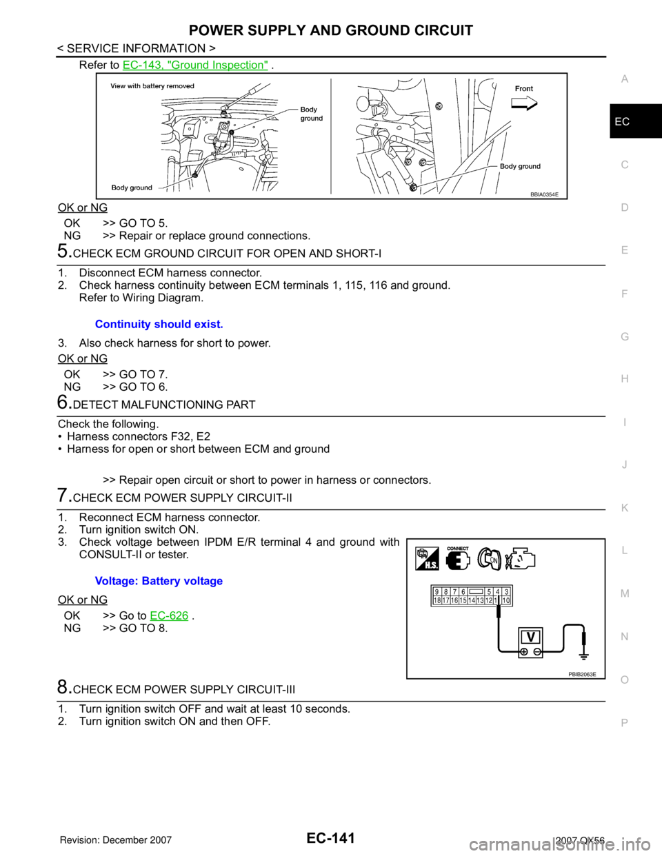
Refer to EC-143, "Ground Inspection" .
OK or NG
OK >> GO TO 5.
NG >> Repair or replace ground connections.
5.CHECK ECM GROUND CIRCUIT FOR OPEN AND SHORT-I
1. Disconnect ECM harness connector.
2. Check harness continuity between ECM terminals 1, 115, 116 and ground.
Refer to Wiring Diagram.
3. Also check harness for short to power.
OK or NG
OK >> GO TO 7.
NG >> GO TO 6.
6.DETECT MALFUNCTIONING PART
Check the following.
• Harness connectors F32, E2
• Harness for open or short between ECM and ground
>> Repair open circuit or short to power in harness or connectors.
7.CHECK ECM POWER SUPPLY CIRCUIT-II
1. Reconnect ECM harness connector.
2. Turn ignition switch ON.
3. Check voltage between IPDM E/R terminal 4 and ground with
CONSULT-II or tester.
OK or NG
OK >> Go to EC-626 .
NG >> GO TO 8.
8.CHECK ECM POWER SUPPLY CIRCUIT-III
1. Turn ignition switch OFF and wait at least 10 seconds.
2. Turn ignition switch ON and then OFF.
BBIA0354E
Continuity should exist.
Voltage: Battery voltage
PBIB2063E