Page 1871 of 3061
CYLINDER BLOCK
EM-101
< SERVICE INFORMATION >
C
D
E
F
G
H
I
J
K
L
MA
EM
N
P O
• If measured value exceeds the repair limit, select main bearings referring to the main bearing inside diame-
ter and crankshaft journal diameter, so that the oil clearance satisfies the standard. Refer to EM-86, "
How to
Select Piston and Bearing".
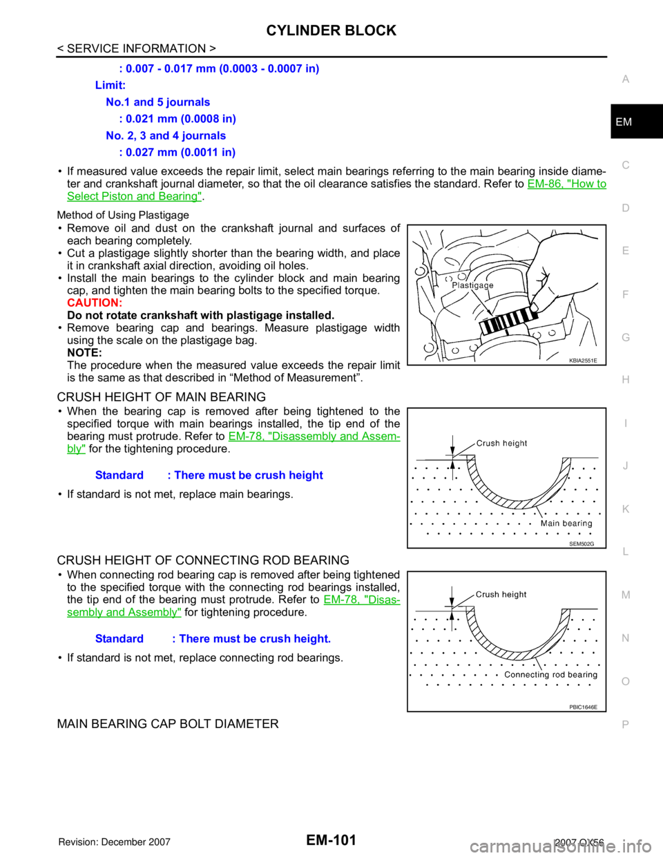
Method of Using Plastigage
• Remove oil and dust on the crankshaft journal and surfaces of
each bearing completely.
• Cut a plastigage slightly shorter than the bearing width, and place
it in crankshaft axial direction, avoiding oil holes.
• Install the main bearings to the cylinder block and main bearing
cap, and tighten the main bearing bolts to the specified torque.
CAUTION:
Do not rotate crankshaft with plastigage installed.
• Remove bearing cap and bearings. Measure plastigage width
using the scale on the plastigage bag.
NOTE:
The procedure when the measured value exceeds the repair limit
is the same as that described in “Method of Measurement”.
CRUSH HEIGHT OF MAIN BEARING
• When the bearing cap is removed after being tightened to the
specified torque with main bearings installed, the tip end of the
bearing must protrude. Refer to EM-78, "
Disassembly and Assem-
bly" for the tightening procedure.
• If standard is not met, replace main bearings.
CRUSH HEIGHT OF CONNECTING ROD BEARING
• When connecting rod bearing cap is removed after being tightened
to the specified torque with the connecting rod bearings installed,
the tip end of the bearing must protrude. Refer to EM-78, "
Disas-
sembly and Assembly" for tightening procedure.
• If standard is not met, replace connecting rod bearings.
MAIN BEARING CAP BOLT DIAMETER
: 0.007 - 0.017 mm (0.0003 - 0.0007 in)
Limit:
No.1 and 5 journals
: 0.021 mm (0.0008 in)
No. 2, 3 and 4 journals
: 0.027 mm (0.0011 in)
KBIA2551E
Standard : There must be crush height
SEM502G
Standard : There must be crush height.
PBIC1646E
Page 1872 of 3061
EM-102
< SERVICE INFORMATION >
CYLINDER BLOCK
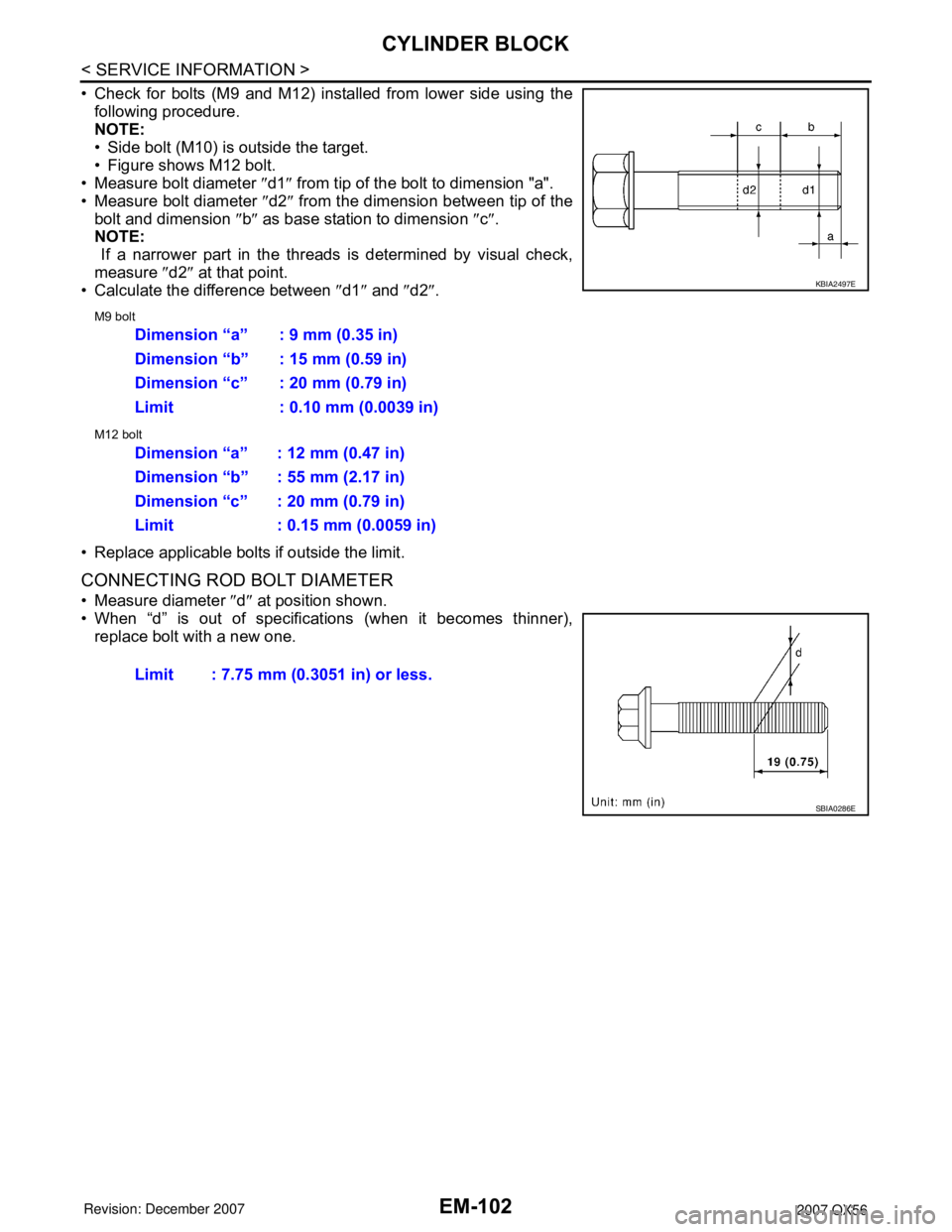
• Check for bolts (M9 and M12) installed from lower side using the
following procedure.
NOTE:
• Side bolt (M10) is outside the target.
• Figure shows M12 bolt.
• Measure bolt diameter ″d1″ from tip of the bolt to dimension "a".
• Measure bolt diameter ″d2″ from the dimension between tip of the
bolt and dimension ″b″ as base station to dimension ″c″.
NOTE:
If a narrower part in the threads is determined by visual check,
measure ″d2″ at that point.
• Calculate the difference between ″d1″ and ″d2″.
M9 bolt
M12 bolt
• Replace applicable bolts if outside the limit.
CONNECTING ROD BOLT DIAMETER
• Measure diameter ″d″ at position shown.
• When “d” is out of specifications (when it becomes thinner),
replace bolt with a new one.
KBIA2497E
Dimension “a” : 9 mm (0.35 in)
Dimension “b” : 15 mm (0.59 in)
Dimension “c” : 20 mm (0.79 in)
Limit : 0.10 mm (0.0039 in)
Dimension “a” : 12 mm (0.47 in)
Dimension “b” : 55 mm (2.17 in)
Dimension “c” : 20 mm (0.79 in)
Limit : 0.15 mm (0.0059 in)
Limit : 7.75 mm (0.3051 in) or less.
SBIA0286E
Page 1873 of 3061
SERVICE DATA AND SPECIFICATIONS (SDS)
EM-103
< SERVICE INFORMATION >
C
D
E
F
G
H
I
J
K
L
MA
EM
N
P O
SERVICE DATA AND SPECIFICATIONS (SDS)
Standard and LimitINFOID:0000000003531548
GENERAL SPECIFICATIONS
DRIVE BELTS
EXHAUST MANIFOLD
Cylinder arrangementV- 8
Displacement cm
3 (cu in)5,552 (338.80)
Bore and stroke mm (in)98 x 92 (3.86 x 3.62)
Valve arrangementDOHC
Firing order1-8-7-3-6-5-4-2
Number of piston ringsCompression 2
Oil 1
Number of main bearings5
Compression ratio9.8:1
C o m p r e s s i o n p r e s s u r e k P a
(kg/cm
2, psi)/rpmStandard 1,520 (15.5, 220)/200
Minimum 1,324 (13.5, 192)/200
Differential limit between cylinders 98 (1.0, 14)/200
Cylinder number
Va l v e t i m i n g
Unit: degree
abcde f
244°232°-8°60°10°54°
SEM957C
PBIC0187E
Tension of drive belts Auto adjustment by auto tensioner
Page 1874 of 3061
EM-104
< SERVICE INFORMATION >
SERVICE DATA AND SPECIFICATIONS (SDS)
Unit: mm (in)
SPARK PLUG
CAMSHAFT AND CAMSHAFT BEARING
Unit: mm (in)
*: Total indicator reading
Valve Lifter
Unit: mm (in)
Valve Clearance
Unit: mm (in)
*: Approximately 80°C (176°F)
Available Valve Lifter
ItemsLimit
Surface distortion Exhaust manifold 0.3 (0.012)
MakeNGK
Standard typeDIFR5A-11
Gap (Nominal)1.1 mm (0.043 in)
ItemsStandard
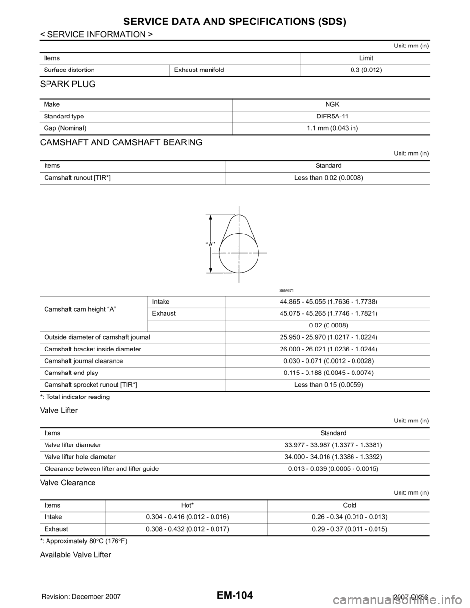
Camshaft runout [TIR*] Less than 0.02 (0.0008)
Camshaft cam height “A”Intake 44.865 - 45.055 (1.7636 - 1.7738)
Exhaust 45.075 - 45.265 (1.7746 - 1.7821)
0.02 (0.0008)
Outside diameter of camshaft journal 25.950 - 25.970 (1.0217 - 1.0224)
Camshaft bracket inside diameter 26.000 - 26.021 (1.0236 - 1.0244)
Camshaft journal clearance 0.030 - 0.071 (0.0012 - 0.0028)
Camshaft end play 0.115 - 0.188 (0.0045 - 0.0074)
Camshaft sprocket runout [TIR*] Less than 0.15 (0.0059)
SEM671
ItemsStandard
Valve lifter diameter 33.977 - 33.987 (1.3377 - 1.3381)
Valve lifter hole diameter 34.000 - 34.016 (1.3386 - 1.3392)
Clearance between lifter and lifter guide 0.013 - 0.039 (0.0005 - 0.0015)
Items Hot* Cold
Intake 0.304 - 0.416 (0.012 - 0.016) 0.26 - 0.34 (0.010 - 0.013)
Exhaust 0.308 - 0.432 (0.012 - 0.017) 0.29 - 0.37 (0.011 - 0.015)
Page 1875 of 3061
SERVICE DATA AND SPECIFICATIONS (SDS)
EM-105
< SERVICE INFORMATION >
C
D
E
F
G
H
I
J
K
L
MA
EM
N
P O
Unit: mm (in)
CYLINDER HEAD
Unit: mm (in)
Identification (stamped) Mark Thickness
N788 7.88 (0.3102)
N790 7.90 (0.3110)
N792 7.92 (0.3118)
N794 7.94 (0.3126)
N796 7.96 (0.3134)
N798 7.98 (0.3142)
N800 8.00 (0.3150)
N802 8.02 (03.157)
N804 8.04 (0.3165)
N806 8.06 (0.3173)
N808 8.08 (0.3181)
N810 8.10 (0.3189)
N812 8.12 (0.3197)
N814 8.14 (0.3205)
N816 8.16 (0.3213)
N818 8.18 (0.3220)
N820 8.20 (0.3228)
N822 8.22 (0.3236)
N824 8.24 (0.3244)
N826 8.26 (0.3252)
N828 8.28 (0.3260)
N830 8.30 (0.3268)
N832 8.32 (0.3276)
N834 8.34 (0.3283)
N836 8.36 (0.3291)
SEM758G
Items Standard Limit
Head surface distortion 0.03 (0.0012) 0.1 (0.004)
Page 1876 of 3061
EM-106
< SERVICE INFORMATION >
SERVICE DATA AND SPECIFICATIONS (SDS)
Valve Dimensions
Unit: mm (in)
Valve Guide
Unit: mm (in)
Nominal cylinder head height “H” 126.3 (4.97) Items Standard Limit
KBIA2554E
Valve head diameter “D”Intake 37.0 - 37.3 (1.457 - 1.469)
Exhaust 31.2 - 31.5 (1.228 - 1.240)
Valve length “L”Intake 96.21- 96.71 (3.7878 - 3.8075)
Exhaust 93.74 - 94.24 (3.6905 - 3.7102)
Valve stem diameter “d”Intake 5.965 - 5.980 (0.2348 - 0.2354)
Exhaust 5.955 - 5.970 (0.2344 - 0.2350)
Valve seat angle “α”Intake
45°15′ - 45°45′
Exhaust
Valve margin “T”Intake 1.1 (0.043)
Exhaust 1.3 (0.051)
SEM188
Items Standard Oversize [0.2 (0.008)] (service)
KBIA2555E
Page 1877 of 3061
SERVICE DATA AND SPECIFICATIONS (SDS)
EM-107
< SERVICE INFORMATION >
C
D
E
F
G
H
I
J
K
L
MA
EM
N
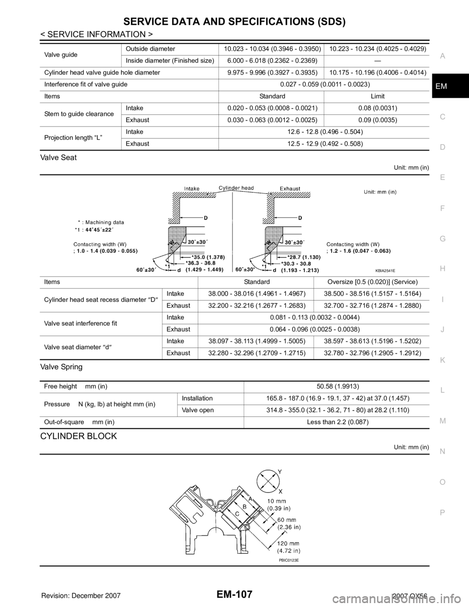
P O Valve Seat
Unit: mm (in)
Va l v e Sp r i n g
CYLINDER BLOCK
Unit: mm (in)
Valve guideOutside diameter 10.023 - 10.034 (0.3946 - 0.3950) 10.223 - 10.234 (0.4025 - 0.4029)
Inside diameter (Finished size) 6.000 - 6.018 (0.2362 - 0.2369) —
Cylinder head valve guide hole diameter 9.975 - 9.996 (0.3927 - 0.3935) 10.175 - 10.196 (0.4006 - 0.4014)
Interference fit of valve guide 0.027 - 0.059 (0.0011 - 0.0023)
Items Standard Limit
Stem to guide clearanceIntake 0.020 - 0.053 (0.0008 - 0.0021) 0.08 (0.0031)
Exhaust 0.030 - 0.063 (0.0012 - 0.0025) 0.09 (0.0035)
Projection length “L”Intake 12.6 - 12.8 (0.496 - 0.504)
Exhaust 12.5 - 12.9 (0.492 - 0.508)
Items Standard Oversize [0.5 (0.020)] (Service)
Cylinder head seat recess diameter ″D″Intake 38.000 - 38.016 (1.4961 - 1.4967) 38.500 - 38.516 (1.5157 - 1.5164)
Exhaust 32.200 - 32.216 (1.2677 - 1.2683) 32.700 - 32.716 (1.2874 - 1.2880)
Valve seat interference fitIntake 0.081 - 0.113 (0.0032 - 0.0044)
Exhaust 0.064 - 0.096 (0.0025 - 0.0038)
Valve seat diameter ″d″Intake 38.097 - 38.113 (1.4999 - 1.5005) 38.597 - 38.613 (1.5196 - 1.5202)
Exhaust 32.280 - 32.296 (1.2709 - 1.2715) 32.780 - 32.796 (1.2905 - 1.2912)
KBIA2541E
Free height mm (in)50.58 (1.9913)
Pressure N (kg, lb) at height mm (in)Installation 165.8 - 187.0 (16.9 - 19.1, 37 - 42) at 37.0 (1.457)
Valve open 314.8 - 355.0 (32.1 - 36.2, 71 - 80) at 28.2 (1.110)
Out-of-square mm (in) Less than 2.2 (0.087)
PBIC0123E
Page 1878 of 3061
EM-108
< SERVICE INFORMATION >
SERVICE DATA AND SPECIFICATIONS (SDS)
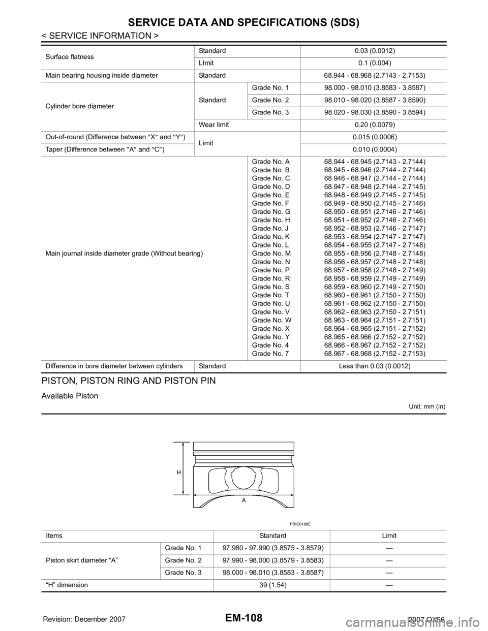
PISTON, PISTON RING AND PISTON PIN
Available Piston
Unit: mm (in)
Surface flatnessStandard 0.03 (0.0012)
LImit 0.1 (0.004)
Main bearing housing inside diameter Standard 68.944 - 68.968 (2.7143 - 2.7153)
Cylinder bore diameterStandardGrade No. 1 98.000 - 98.010 (3.8583 - 3.8587)
Grade No. 2 98.010 - 98.020 (3.8587 - 3.8590)
Grade No. 3 98.020 - 98.030 (3.8590 - 3.8594)
Wear limit 0.20 (0.0079)
Out-of-round (Difference between ″X″ and ″Y″)
Limit0.015 (0.0006)
Taper (Difference between ″A″ and ″C″) 0.010 (0.0004)
Main journal inside diameter grade (Without bearing)Grade No. A
Grade No. B
Grade No. C
Grade No. D
Grade No. E
Grade No. F
Grade No. G
Grade No. H
Grade No. J
Grade No. K
Grade No. L
Grade No. M
Grade No. N
Grade No. P
Grade No. R
Grade No. S
Grade No. T
Grade No. U
Grade No. V
Grade No. W
Grade No. X
Grade No. Y
Grade No. 4
Grade No. 768.944 - 68.945 (2.7143 - 2.7144)
68.945 - 68.946 (2.7144 - 2.7144)
68.946 - 68.947 (2.7144 - 2.7144)
68.947 - 68.948 (2.7144 - 2.7145)
68.948 - 68.949 (2.7145 - 2.7145)
68.949 - 68.950 (2.7145 - 2.7146)
68.950 - 68.951 (2.7146 - 2.7146)
68.951 - 68.952 (2.7146 - 2.7146)
68.952 - 68.953 (2.7146 - 2.7147)
68.953 - 68.954 (2.7147 - 2.7147)
68.954 - 68.955 (2.7147 - 2.7148)
68.955 - 68.956 (2.7148 - 2.7148)
68.956 - 68.957 (2.7148 - 2.7148)
68.957 - 68.958 (2.7148 - 2.7149)
68.958 - 68.959 (2.7149 - 2.7149)
68.959 - 68.960 (2.7149 - 2.7150)
68.960 - 68.961 (2.7150 - 2.7150)
68.961 - 68.962 (2.7150 - 2.7150)
68.962 - 68.963 (2.7150 - 2.7151)
68.963 - 68.964 (2.7151 - 2.7151)
68.964 - 68.965 (2.7151 - 2.7152)
68.965 - 68.966 (2.7152 - 2.7152)
68.966 - 68.967 (2.7152 - 2.7152)
68.967 - 68.968 (2.7152 - 2.7153)
Difference in bore diameter between cylinders Standard Less than 0.03 (0.0012)
Items Standard Limit
Piston skirt diameter “A”Grade No. 1 97.980 - 97.990 (3.8575 - 3.8579) —
Grade No. 2 97.990 - 98.000 (3.8579 - 3.8583) —
Grade No. 3 98.000 - 98.010 (3.8583 - 3.8587) —
“H” dimension 39 (1.54) —
PBIC0188E