Page 1028 of 3061
COMBINATION METERSDI-17
< SERVICE INFORMATION >
C
DE
F
G H
I
J
L
M A
B
DI
N
O P
Refer to DI-9, "Wiring Diagram - METER -".
OK or NG
OK >> GO TO 2.
NG >> If fuse is blown, be sure to eliminate caus e of malfunction before installing new fuse. Refer to PG-
3.
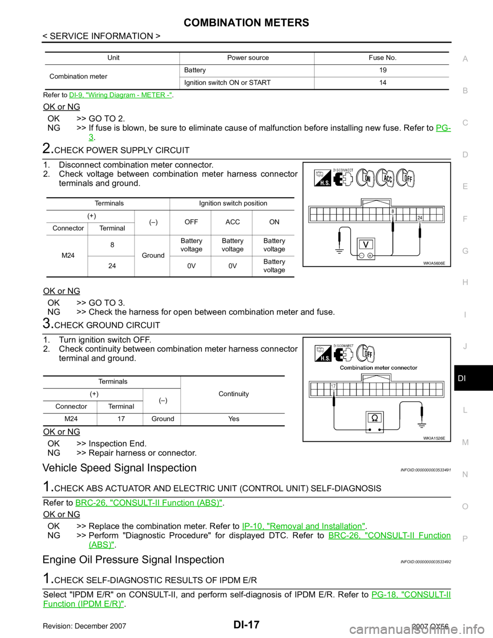
2.CHECK POWER SUPPLY CIRCUIT
1. Disconnect combination meter connector.
2. Check voltage between combination meter harness connector terminals and ground.
OK or NG
OK >> GO TO 3.
NG >> Check the harness for open between combination meter and fuse.
3.CHECK GROUND CIRCUIT
1. Turn ignition switch OFF.
2. Check continuity between combination meter harness connector terminal and ground.
OK or NG
OK >> Inspection End.
NG >> Repair harness or connector.
Vehicle Speed Signal InspectionINFOID:0000000003533491
1.CHECK ABS ACTUATOR AND ELECTRIC UNIT (CONTROL UNIT) SELF-DIAGNOSIS
Refer to BRC-26, "
CONSULT-II Function (ABS)".
OK or NG
OK >> Replace the combination meter. Refer to IP-10, "Removal and Installation".
NG >> Perform "Diagnostic Procedure" for displayed DTC. Refer to BRC-26, "
CONSULT-II Function
(ABS)".
Engine Oil Pressure Signal InspectionINFOID:0000000003533492
1.CHECK SELF-DIAGNOSTIC RESULTS OF IPDM E/R
Select "IPDM E/R" on CONSULT-II, and perform self-diagnosis of IPDM E/R. Refer to PG-18, "
CONSULT-II
Function (IPDM E/R)".
Unit Power source Fuse No.
Combination meter Battery 19
Ignition switch ON or START 14
Terminals Ignition switch position
(+) (–) OFF ACC ON
Connector Terminal
M24 8
Ground Battery
voltage Battery
voltage Battery
voltage
24 0V 0V Battery
voltage
WKIA5606E
Te r m i n a l s
Continuity
(+)
(–)
Connector Terminal
M24 17 Ground Yes
WKIA1526E
Page 1029 of 3061
DI-18
< SERVICE INFORMATION >
COMBINATION METERS
Self-diagnostic results content
No malfunction detected>>GO TO 2.
Malfunction detected>>GO TO PG-18, "
CONSULT-II Function (IPDM E/R)".
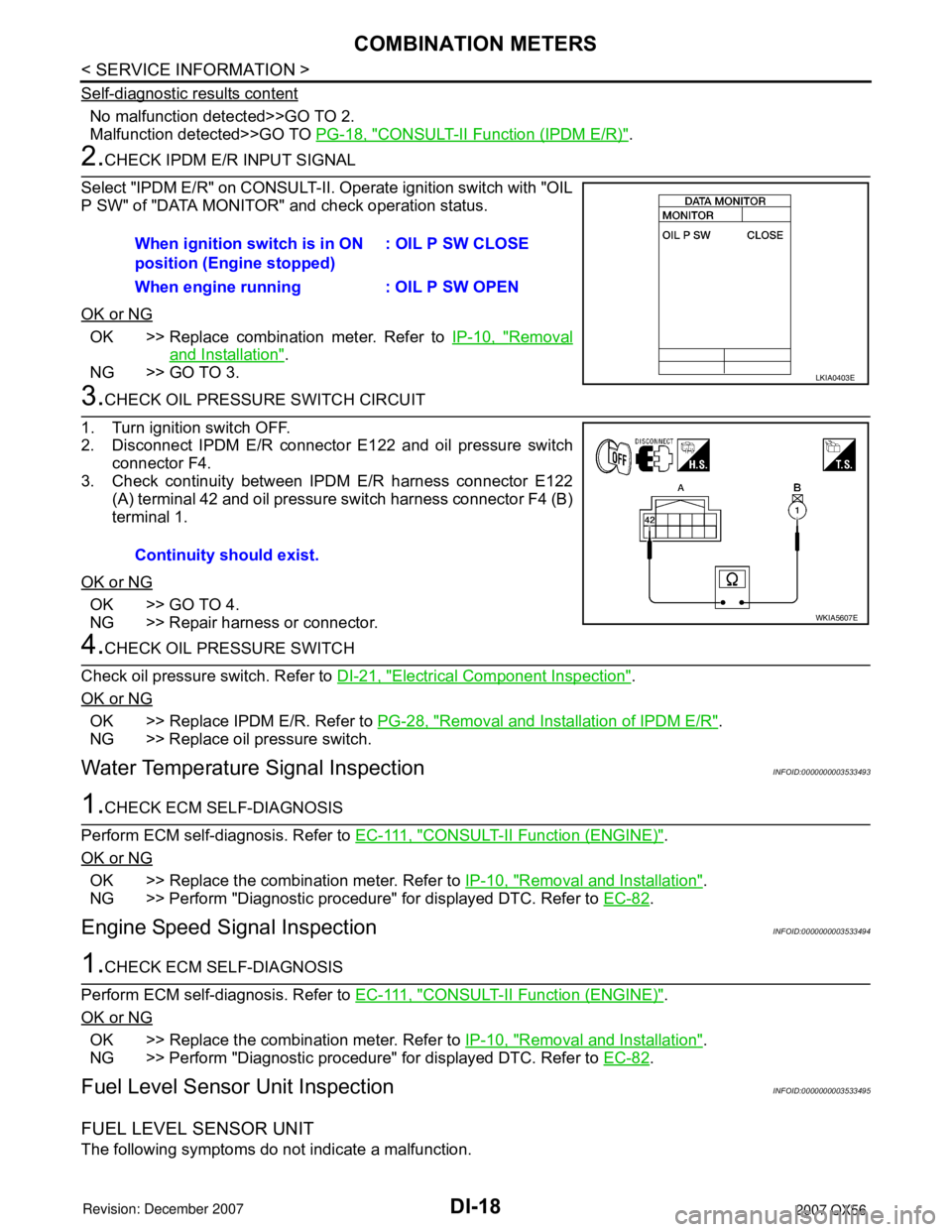
2.CHECK IPDM E/R INPUT SIGNAL
Select "IPDM E/R" on CONSULT-II. Operate ignition switch with "OIL
P SW" of "DATA MONITOR" and check operation status.
OK or NG
OK >> Replace combination meter. Refer to IP-10, "Removal
and Installation".
NG >> GO TO 3.
3.CHECK OIL PRESSURE SWITCH CIRCUIT
1. Turn ignition switch OFF.
2. Disconnect IPDM E/R connector E122 and oil pressure switch
connector F4.
3. Check continuity between IPDM E/R harness connector E122 (A) terminal 42 and oil pressure switch harness connector F4 (B)
terminal 1.
OK or NG
OK >> GO TO 4.
NG >> Repair harness or connector.
4.CHECK OIL PRESSURE SWITCH
Check oil pressure switch. Refer to DI-21, "
Electrical Component Inspection".
OK or NG
OK >> Replace IPDM E/R. Refer to PG-28, "Removal and Installation of IPDM E/R".
NG >> Replace oil pressure switch.
Water Temperature Signal InspectionINFOID:0000000003533493
1.CHECK ECM SELF-DIAGNOSIS
Perform ECM self-diagnosis. Refer to E C - 111 , "
CONSULT-II Function (ENGINE)".
OK or NG
OK >> Replace the combination meter. Refer to IP-10, "Removal and Installation".
NG >> Perform "Diagnostic procedure" for displayed DTC. Refer to EC-82
.
Engine Speed Signal InspectionINFOID:0000000003533494
1.CHECK ECM SELF-DIAGNOSIS
Perform ECM self-diagnosis. Refer to E C - 111 , "
CONSULT-II Function (ENGINE)".
OK or NG
OK >> Replace the combination meter. Refer to IP-10, "Removal and Installation".
NG >> Perform "Diagnostic procedure" for displayed DTC. Refer to EC-82
.
Fuel Level Sensor Unit InspectionINFOID:0000000003533495
FUEL LEVEL SENSOR UNIT
The following symptoms do not indicate a malfunction.When ignition switch is in ON
position (Engine stopped)
: OIL P SW CLOSE
When engine running : OIL P SW OPEN
LKIA0403E
Continuity should exist.
WKIA5607E
Page 1032 of 3061
COMBINATION METERS
DI-21
< SERVICE INFORMATION >
C
D
E
F
G
H
I
J
L
MA
B
DI
N
O
P
4.CHECK POINTER MOVEMENT TO EMPTY-POSITION
During driving, does the fuel gauge move gradually toward empty-position?
YES or NO
YES >> Check the fuel level sensor unit. Refer to DI-21, "Electrical Component Inspection".
NO >> Check fuel level sensor unit installation, and determine whether the float arm interferes or binds
with any of the internal components in the fuel tank.
Electrical Component InspectionINFOID:0000000003533498
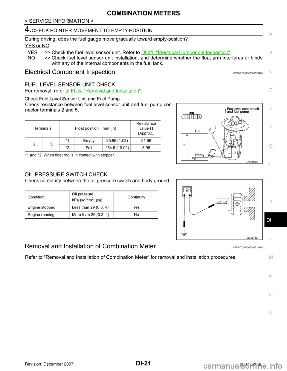
FUEL LEVEL SENSOR UNIT CHECK
For removal, refer to FL-5, "Removal and Installation".
Check Fuel Level Sensor Unit and Fuel Pump
Check resistance between fuel level sensor unit and fuel pump con-
nector terminals 2 and 5.
*1 and *2: When float rod is in contact with stopper.
OIL PRESSURE SWITCH CHECK
Check continuity between the oil pressure switch and body ground.
Removal and Installation of Combination MeterINFOID:0000000003533499
Refer to "Removal and Installation of Combination Meter" for removal and installation procedures.
Terminals Float position mm (in)Resistance
value Ω
(Approx.)
25*1 Empty 25.86 (1.02) 81.66
*2 Full 254.6 (10.02) 6.98
LKIA0402E
ConditionOil pressure
kPa (kg/cm2, psi)Continuity
Engine stopped Less than 29 (0.3, 4) Yes
Engine running More than 29 (0.3, 4) No
ELF0044D
Page 1043 of 3061
DI-32
< SERVICE INFORMATION >
WARNING LAMPS
4WD Models
Oil Pressure Warning Lamp Stays Off (Ignition Switch ON)INFOID:0000000003533506
1.CHECK SELF-DIAGNOSTIC RESULTS OF IPDM E/R
Select "IPDM E/R" on CONSULT-II, and perform self-diagnosis of IPDM E/R. Refer to PG-18, "
CONSULT-II
Function (IPDM E/R)".
Self-diagnostic results content
WKWA5140E
Page 1044 of 3061
WARNING LAMPS
DI-33
< SERVICE INFORMATION >
C
D
E
F
G
H
I
J
L
MA
B
DI
N
O
P
No malfunction detected>>GO TO 2.
Malfunction detected>>GO TO PG-18, "
CONSULT-II Function (IPDM E/R)".
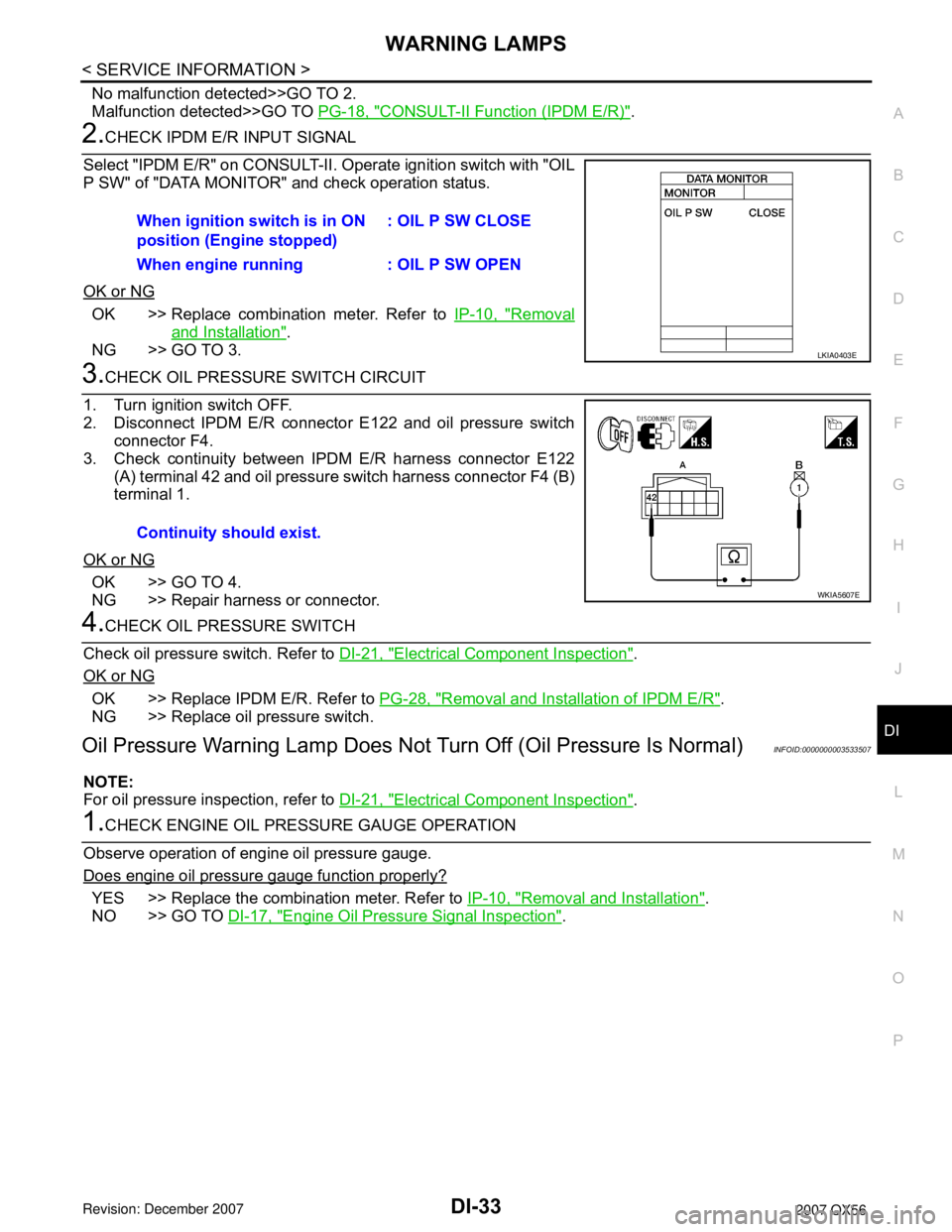
2.CHECK IPDM E/R INPUT SIGNAL
Select "IPDM E/R" on CONSULT-II. Operate ignition switch with "OIL
P SW" of "DATA MONITOR" and check operation status.
OK or NG
OK >> Replace combination meter. Refer to IP-10, "Removal
and Installation".
NG >> GO TO 3.
3.CHECK OIL PRESSURE SWITCH CIRCUIT
1. Turn ignition switch OFF.
2. Disconnect IPDM E/R connector E122 and oil pressure switch
connector F4.
3. Check continuity between IPDM E/R harness connector E122
(A) terminal 42 and oil pressure switch harness connector F4 (B)
terminal 1.
OK or NG
OK >> GO TO 4.
NG >> Repair harness or connector.
4.CHECK OIL PRESSURE SWITCH
Check oil pressure switch. Refer to DI-21, "
Electrical Component Inspection".
OK or NG
OK >> Replace IPDM E/R. Refer to PG-28, "Removal and Installation of IPDM E/R".
NG >> Replace oil pressure switch.
Oil Pressure Warning Lamp Does Not Turn Off (Oil Pressure Is Normal)INFOID:0000000003533507
NOTE:
For oil pressure inspection, refer to DI-21, "
Electrical Component Inspection".
1.CHECK ENGINE OIL PRESSURE GAUGE OPERATION
Observe operation of engine oil pressure gauge.
Does engine oil pressure gauge function properly?
YES >> Replace the combination meter. Refer to IP-10, "Removal and Installation".
NO >> GO TO DI-17, "
Engine Oil Pressure Signal Inspection". When ignition switch is in ON
position (Engine stopped): OIL P SW CLOSE
When engine running : OIL P SW OPEN
LKIA0403E
Continuity should exist.
WKIA5607E
Page 1101 of 3061
EC-18
< SERVICE INFORMATION >
PRECAUTIONS
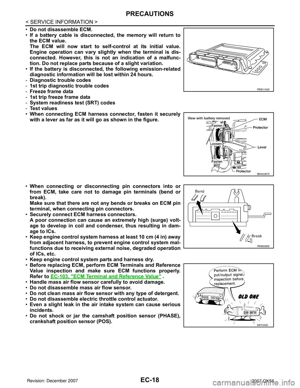
•Do not disassemble ECM.
•If a battery cable is disconnected, the memory will return to
the ECM value.
The ECM will now start to self-control at its initial value.
Engine operation can vary slightly when the terminal is dis-
connected. However, this is not an indication of a malfunc-
tion. Do not replace parts because of a slight variation.
•If the battery is disconnected, the following emission-related
diagnostic information will be lost within 24 hours.
-Diagnostic trouble codes
-1st trip diagnostic trouble codes
-Freeze frame data
-1st trip freeze frame data
-System readiness test (SRT) codes
-Test values
•When connecting ECM harness connector, fasten it securely
with a lever as far as it will go as shown in the figure.
•When connecting or disconnecting pin connectors into or
from ECM, take care not to damage pin terminals (bend or
break).
Make sure that there are not any bends or breaks on ECM pin
terminal, when connecting pin connectors.
•Securely connect ECM harness connectors.
A poor connection can cause an extremely high (surge) volt-
age to develop in coil and condenser, thus resulting in dam-
age to ICs.
•Keep engine control system harness at least 10 cm (4 in) away
from adjacent harness, to prevent engine control system mal-
functions due to receiving external noise, degraded operation
of ICs, etc.
•Keep engine control system parts and harness dry.
•Before replacing ECM, perform ECM Terminals and Reference
Value inspection and make sure ECM functions properly.
Refer to EC-103, "
ECM Terminal and Reference Value" .
•Handle mass air flow sensor carefully to avoid damage.
•Do not disassemble mass air flow sensor.
•Do not clean mass air flow sensor with any type of detergent.
•Do not disassemble electric throttle control actuator.
•Even a slight leak in the air intake system can cause serious
incidents.
•Do not shock or jar the camshaft position sensor (PHASE),
crankshaft position sensor (POS).
PBIB1164E
BBIA0387E
PBIB0090E
MEF040D
Page 1159 of 3061
EC-76
< SERVICE INFORMATION >
BASIC SERVICE PROCEDURE
2. Check ignition timing.
Method B
1. Remove ignition coil No.1.
2. Connect ignition coil No.1 and spark plug with suitable high-ten-
sion wire as shown, and attach timing light clamp to this wire.
3. Check ignition timing.
BBIA0379E
BBIA0360E
BBIA0378E
SEF011V
BBIA0379E
Page 1173 of 3061

EC-90
< SERVICE INFORMATION >
TROUBLE DIAGNOSIS
Symptom Matrix Chart
INFOID:0000000003531620
SYSTEM — BASIC ENGINE CONTROL SYSTEM
SYMPTOM
Refer-
ence page
HARD/NO START/RESTART (EXCP. HA)
ENGINE STALL
HESITATION/SURGING/FLAT SPOT
SPARK KNOCK/DETONATION
LACK OF POWER/POOR ACCELERATION
HIGH IDLE/LOW IDLE
ROUGH IDLE/HUNTING
IDLING VIBRATION
SLOW/NO RETURN TO IDLE
OVERHEATS/WATER TEMPERATURE HIGH
EXCESSIVE FUEL CONSUMPTION
EXCESSIVE OIL CONSUMPTION
BATTERY DEAD (UNDER CHARGE)
Warranty symptom code AA AB AC AD AE AF AG AH AJ AK AL AM HA
Fuel Fuel pump circuit 11232 22 3 2EC-613
Fuel pressure regulator system 334444444 4EC-80
Injector circuit 11232 22 2EC-608
Evaporative emission system 334444444 4EC-33
Air Positive crankcase ventilation sys-
tem
334444444 41EC-45
Incorrect idle speed adjustment 1 1 1 1 1EC-71
Electric throttle control actuator 112332222 2 2EC-543
,
EC-548
,
EC-554
,
EC-559
IgnitionIncorrect ignition timing adjustment 33111 11 1EC-71
Ignition circuit 11222 22 2EC-626
Main power supply and ground circuit 22333 33 23EC-139
Mass air flow sensor circuit
1
122
222 2EC-186,
EC-194
Engine coolant temperature sensor circuit
333EC-205,
EC-217
Air fuel ratio (A/F) sensor 1 circuitEC-225
,
EC-234
,
EC-242
,
EC-250
,
EC-588
Throttle position sensor circuit
22EC-210
,
EC-318
,
EC-477
,
EC-479
,
EC-574
Accelerator pedal position sensor circuit 3 2 1EC-440
,
EC-561
,
EC-567
,
EC-581
Knock sensor circuit 2 3EC-332
Crankshaft position sensor (POS) circuit 2 2EC-336