2007 INFINITI QX56 hood open
[x] Cancel search: hood openPage 786 of 3061

VEHICLE SECURITY (THEFT WARNING) SYSTEM
BL-75
< SERVICE INFORMATION >
C
D
E
F
G
H
J
K
L
MA
B
BL
N
O
P
Check continuity between front or rear door switch terminal 2 and
exposed metal of switch while pressing and releasing switch.
BACK DOOR
Check continuity between back door latch connector (A) D503 termi-
nals 7 and 8 while pressing (closing back door) and releasing (open-
ing back door) switch.
OK or NG
OK >> (Front and rear doors) Switch circuit is OK.
OK >> (Back door) GO TO 4.
NG >> Replace door switch.
4.CHECK BACK DOOR SWITCH GROUND
Check continuity between back door latch connector terminal 8 and
ground.
OK or NG
OK >> Back door switch circuit is OK.
NG >> Repair or replace harness.
Hood Switch CheckINFOID:0000000003532950
1.CHECK HOOD SWITCH
Check hood switch and hood fitting condition.
OK or NG
OK >> GO TO 2.
NG >> Adjust installation of hood switch.
2.CHECK HOOD SWITCH INPUT SIGNAL
With CONSULT-II
Check "HOOD SW" in "DATA MONITOR" mode with CONSULT-II.Door switch is released : Continuity should exist.
Door switch is pushed : Continuity should not exist.
WIIA0644E
When back door is open : Continuity should exist.
When back door is closed : Continuity should not exist.
WIIA0752E
8 - Ground : Continuity should exist.
LIIA0828E
When hood is open : HOOD SW ON
When hood is closed : HOOD SW OFF
LIIA0038E
Page 787 of 3061

BL-76
< SERVICE INFORMATION >
VEHICLE SECURITY (THEFT WARNING) SYSTEM
Without CONSULT-II
Check voltage between IPDM E/R harness connector E122 terminal
41 and ground.
OK or NG
OK >> Hood switch is OK.
NG >> GO TO 3.
3.CHECK HOOD SWITCH
1. Turn ignition switch OFF.
2. Disconnect hood switch connector.
3. Check continuity between hood switch terminals 1 and 2.
OK or NG
OK >> Check the following:
• Hood switch ground circuit.
• Harness for open or short between hood switch and
IPDM E/R
NG >> Replace hood switch.
Combination Meter (Security Indicator Lamp) CheckINFOID:0000000003532951
1.SECURITY INDICATOR LAMP ACTIVE TEST
With CONSULT-II
Check "THEFT IND” in "ACTIVE TEST" mode with CONSULT-II.
Without CONSULT-II
1. Disconnect BCM.
ConnectorTe r m i n a l
Condition of
hoodVoltage (V)
(Approx.)
(+) (-)
E122 41 GroundOpen 0
Closed Battery voltage
WIIA0601E
Terminals Condition Continuity
1- 2Pressed No
Released Yes
LIIA0040E
LIIA0044E
Page 1154 of 3061
BASIC SERVICE PROCEDURE
EC-71
< SERVICE INFORMATION >
C
D
E
F
G
H
I
J
K
L
MA
EC
N
P O
BASIC SERVICE PROCEDURE
Basic InspectionINFOID:0000000003531609
1.INSPECTION START
1. Check service records for any recent repairs that may indicate a related malfunction, or a current need for
scheduled maintenance.
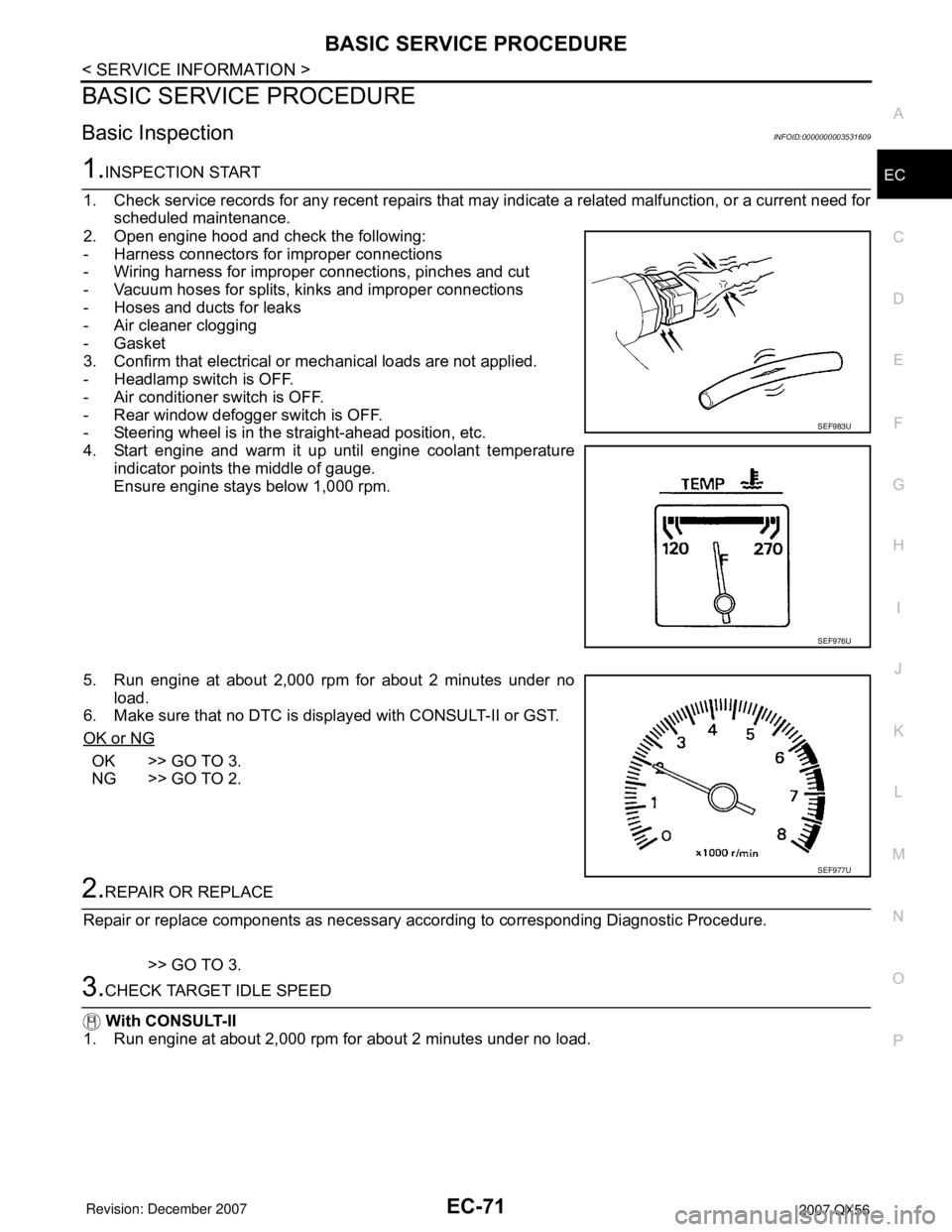
2. Open engine hood and check the following:
- Harness connectors for improper connections
- Wiring harness for improper connections, pinches and cut
- Vacuum hoses for splits, kinks and improper connections
- Hoses and ducts for leaks
- Air cleaner clogging
- Gasket
3. Confirm that electrical or mechanical loads are not applied.
- Headlamp switch is OFF.
- Air conditioner switch is OFF.
- Rear window defogger switch is OFF.
- Steering wheel is in the straight-ahead position, etc.
4. Start engine and warm it up until engine coolant temperature
indicator points the middle of gauge.
Ensure engine stays below 1,000 rpm.
5. Run engine at about 2,000 rpm for about 2 minutes under no
load.
6. Make sure that no DTC is displayed with CONSULT-II or GST.
OK or NG
OK >> GO TO 3.
NG >> GO TO 2.
2.REPAIR OR REPLACE
Repair or replace components as necessary according to corresponding Diagnostic Procedure.
>> GO TO 3.
3.CHECK TARGET IDLE SPEED
With CONSULT-II
1. Run engine at about 2,000 rpm for about 2 minutes under no load.
SEF983U
SEF976U
SEF977U
Page 1179 of 3061
EC-96
< SERVICE INFORMATION >
TROUBLE DIAGNOSIS
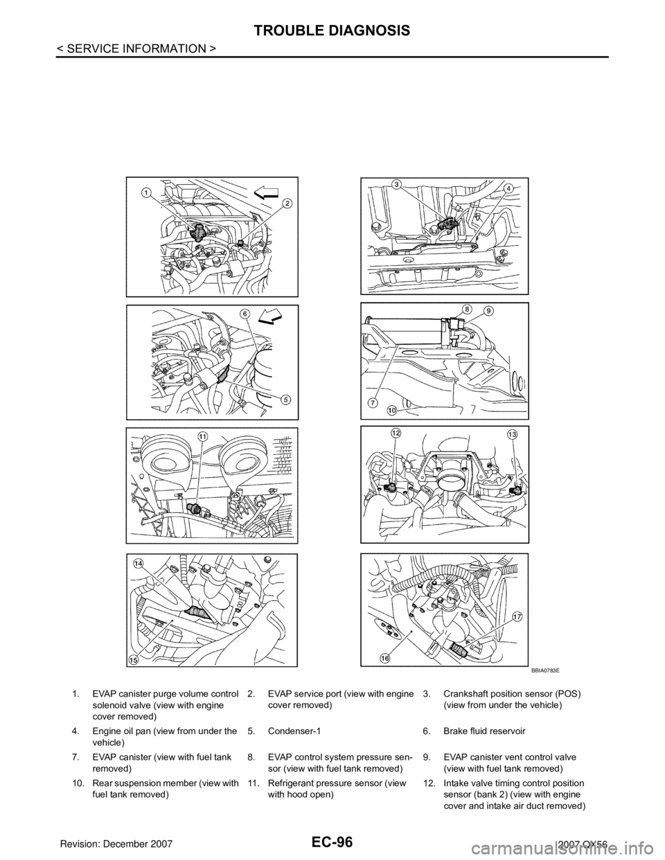
1. EVAP canister purge volume control
solenoid valve (view with engine
cover removed)2. EVAP service port (view with engine
cover removed)3. Crankshaft position sensor (POS)
(view from under the vehicle)
4. Engine oil pan (view from under the
vehicle)5. Condenser-1 6. Brake fluid reservoir
7. EVAP canister (view with fuel tank
removed)8. EVAP control system pressure sen-
sor (view with fuel tank removed)9. EVAP canister vent control valve
(view with fuel tank removed)
10. Rear suspension member (view with
fuel tank removed)11. Refrigerant pressure sensor (view
with hood open)12. Intake valve timing control position
sensor (bank 2) (view with engine
cover and intake air duct removed)
BBIA0783E
Page 1206 of 3061
TROUBLE DIAGNOSIS
EC-123
< SERVICE INFORMATION >
C
D
E
F
G
H
I
J
K
L
MA
EC
N
P O
INSPECTION PROCEDURE
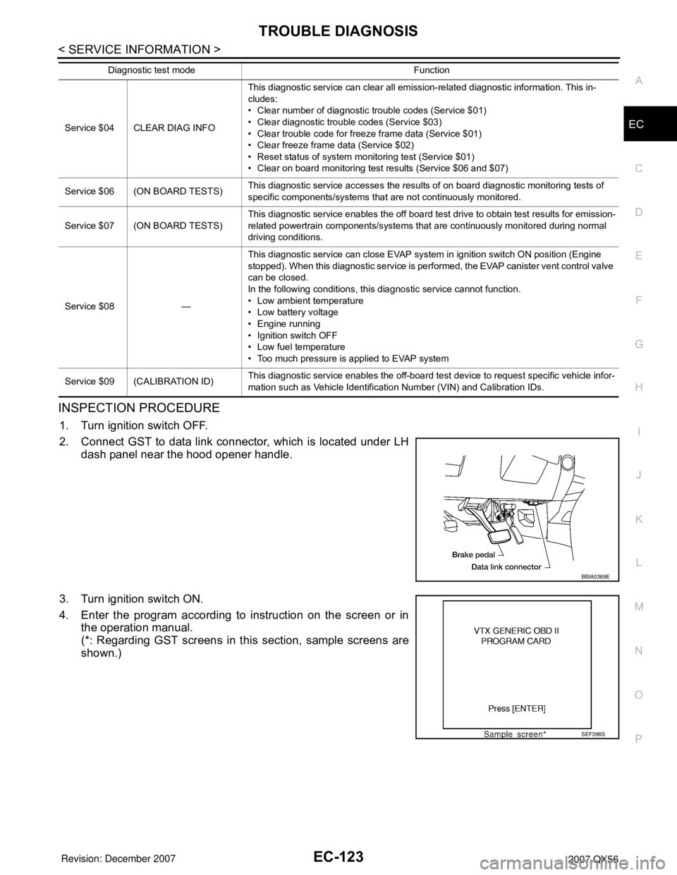
1. Turn ignition switch OFF.
2. Connect GST to data link connector, which is located under LH
dash panel near the hood opener handle.
3. Turn ignition switch ON.
4. Enter the program according to instruction on the screen or in
the operation manual.
(*: Regarding GST screens in this section, sample screens are
shown.)
Service $04 CLEAR DIAG INFOThis diagnostic service can clear all emission-related diagnostic information. This in-
cludes:
• Clear number of diagnostic trouble codes (Service $01)
• Clear diagnostic trouble codes (Service $03)
• Clear trouble code for freeze frame data (Service $01)
• Clear freeze frame data (Service $02)
• Reset status of system monitoring test (Service $01)
• Clear on board monitoring test results (Service $06 and $07)
Service $06 (ON BOARD TESTS)This diagnostic service accesses the results of on board diagnostic monitoring tests of
specific components/systems that are not continuously monitored.
Service $07 (ON BOARD TESTS)This diagnostic service enables the off board test drive to obtain test results for emission-
related powertrain components/systems that are continuously monitored during normal
driving conditions.
Service $08 —This diagnostic service can close EVAP system in ignition switch ON position (Engine
stopped). When this diagnostic service is performed, the EVAP canister vent control valve
can be closed.
In the following conditions, this diagnostic service cannot function.
• Low ambient temperature
• Low battery voltage
• Engine running
• Ignition switch OFF
• Low fuel temperature
• Too much pressure is applied to EVAP system
Service $09 (CALIBRATION ID)This diagnostic service enables the off-board test device to request specific vehicle infor-
mation such as Vehicle Identification Number (VIN) and Calibration IDs. Diagnostic test mode Function
BBIA0369E
SEF398S
Page 1344 of 3061
DTC P0137, P0157 HO2S2
EC-261
< SERVICE INFORMATION >
C
D
E
F
G
H
I
J
K
L
MA
EC
N
P O
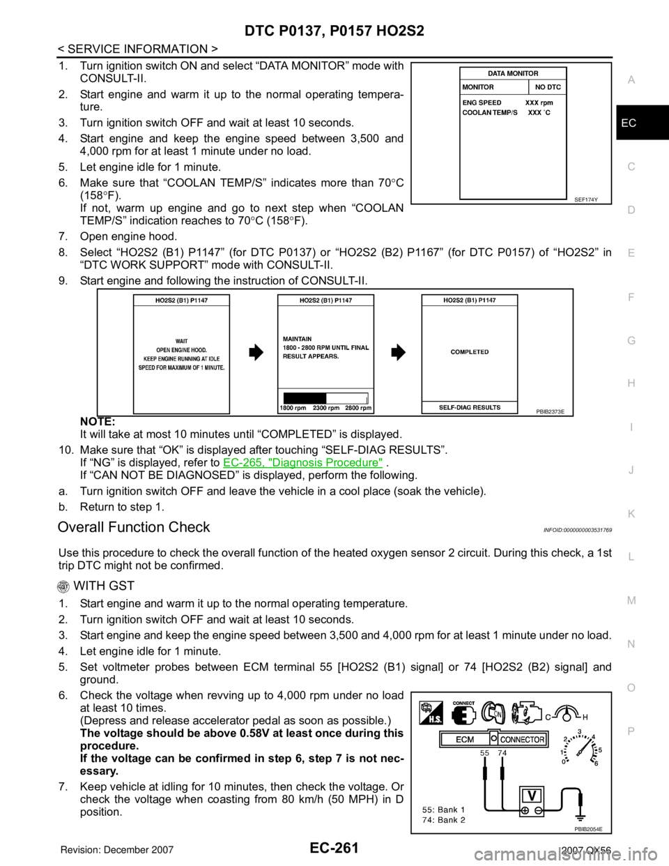
1. Turn ignition switch ON and select “DATA MONITOR” mode with
CONSULT-II.
2. Start engine and warm it up to the normal operating tempera-
ture.
3. Turn ignition switch OFF and wait at least 10 seconds.
4. Start engine and keep the engine speed between 3,500 and
4,000 rpm for at least 1 minute under no load.
5. Let engine idle for 1 minute.
6. Make sure that “COOLAN TEMP/S” indicates more than 70°C
(158°F).
If not, warm up engine and go to next step when “COOLAN
TEMP/S” indication reaches to 70°C (158°F).
7. Open engine hood.
8. Select “HO2S2 (B1) P1147” (for DTC P0137) or “HO2S2 (B2) P1167” (for DTC P0157) of “HO2S2” in
“DTC WORK SUPPORT” mode with CONSULT-II.
9. Start engine and following the instruction of CONSULT-II.
NOTE:
It will take at most 10 minutes until “COMPLETED” is displayed.
10. Make sure that “OK” is displayed after touching “SELF-DIAG RESULTS”.
If “NG” is displayed, refer to EC-265, "
Diagnosis Procedure" .
If “CAN NOT BE DIAGNOSED” is displayed, perform the following.
a. Turn ignition switch OFF and leave the vehicle in a cool place (soak the vehicle).
b. Return to step 1.
Overall Function CheckINFOID:0000000003531769
Use this procedure to check the overall function of the heated oxygen sensor 2 circuit. During this check, a 1st
trip DTC might not be confirmed.
WITH GST
1. Start engine and warm it up to the normal operating temperature.
2. Turn ignition switch OFF and wait at least 10 seconds.
3. Start engine and keep the engine speed between 3,500 and 4,000 rpm for at least 1 minute under no load.
4. Let engine idle for 1 minute.
5. Set voltmeter probes between ECM terminal 55 [HO2S2 (B1) signal] or 74 [HO2S2 (B2) signal] and
ground.
6. Check the voltage when revving up to 4,000 rpm under no load
at least 10 times.
(Depress and release accelerator pedal as soon as possible.)
The voltage should be above 0.58V at least once during this
procedure.
If the voltage can be confirmed in step 6, step 7 is not nec-
essary.
7. Keep vehicle at idling for 10 minutes, then check the voltage. Or
check the voltage when coasting from 80 km/h (50 MPH) in D
position.
SEF174Y
PBIB2373E
PBIB2054E
Page 1354 of 3061
DTC P0138, P0158 HO2S2
EC-271
< SERVICE INFORMATION >
C
D
E
F
G
H
I
J
K
L
MA
EC
N
P O
DTC Confirmation ProcedureINFOID:0000000003531777
Perform PROCEDURE FOR MALFUNCTION A first.
If DTC cannot be confirmed, perform PROCEDURE FOR MALFUNCTION B.
NOTE:
If DTC Confirmation Procedure has been previously conducted, always turn ignition switch OFF and wait at
least 10 seconds before conducting the next test.
PROCEDURE FOR MALFUNCTION A
With CONSULT-II
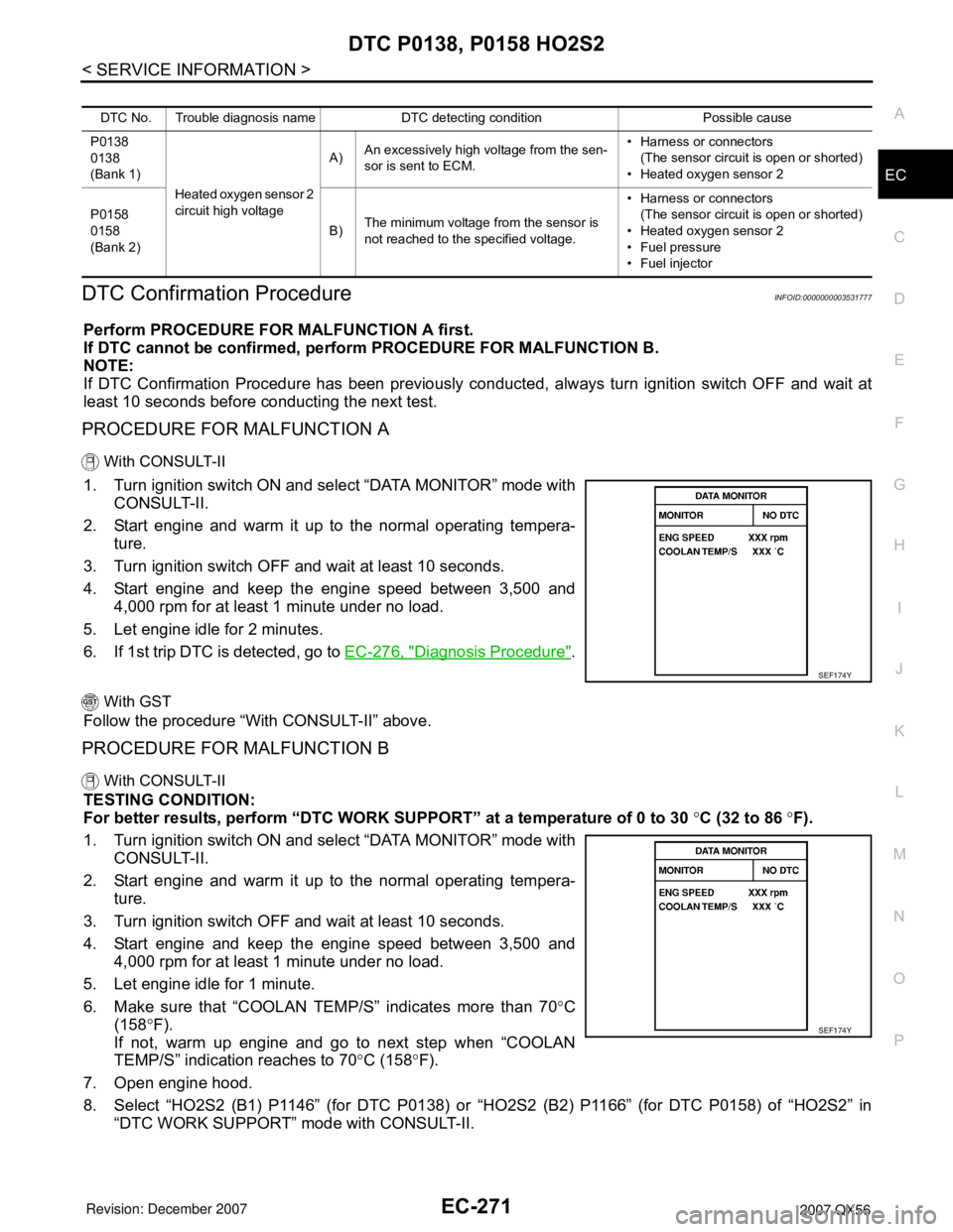
1. Turn ignition switch ON and select “DATA MONITOR” mode with
CONSULT-II.
2. Start engine and warm it up to the normal operating tempera-
ture.
3. Turn ignition switch OFF and wait at least 10 seconds.
4. Start engine and keep the engine speed between 3,500 and
4,000 rpm for at least 1 minute under no load.
5. Let engine idle for 2 minutes.
6. If 1st trip DTC is detected, go to EC-276, "
Diagnosis Procedure".
With GST
Follow the procedure “With CONSULT-II” above.
PROCEDURE FOR MALFUNCTION B
With CONSULT-II
TESTING CONDITION:
For better results, perform “DTC WORK SUPPORT” at a temperature of 0 to 30 °C (32 to 86 °F).
1. Turn ignition switch ON and select “DATA MONITOR” mode with
CONSULT-II.
2. Start engine and warm it up to the normal operating tempera-
ture.
3. Turn ignition switch OFF and wait at least 10 seconds.
4. Start engine and keep the engine speed between 3,500 and
4,000 rpm for at least 1 minute under no load.
5. Let engine idle for 1 minute.
6. Make sure that “COOLAN TEMP/S” indicates more than 70°C
(158°F).
If not, warm up engine and go to next step when “COOLAN
TEMP/S” indication reaches to 70°C (158°F).
7. Open engine hood.
8. Select “HO2S2 (B1) P1146” (for DTC P0138) or “HO2S2 (B2) P1166” (for DTC P0158) of “HO2S2” in
“DTC WORK SUPPORT” mode with CONSULT-II.
DTC No. Trouble diagnosis name DTC detecting condition Possible cause
P0138
0138
(Bank 1)
Heated oxygen sensor 2
circuit high voltageA)An excessively high voltage from the sen-
sor is sent to ECM.• Harness or connectors
(The sensor circuit is open or shorted)
• Heated oxygen sensor 2
P0158
0158
(Bank 2)B)The minimum voltage from the sensor is
not reached to the specified voltage.• Harness or connectors
(The sensor circuit is open or shorted)
• Heated oxygen sensor 2
• Fuel pressure
• Fuel injector
SEF174Y
SEF174Y
Page 1366 of 3061
DTC P0139, P0159 HO2S2
EC-283
< SERVICE INFORMATION >
C
D
E
F
G
H
I
J
K
L
MA
EC
N
P O
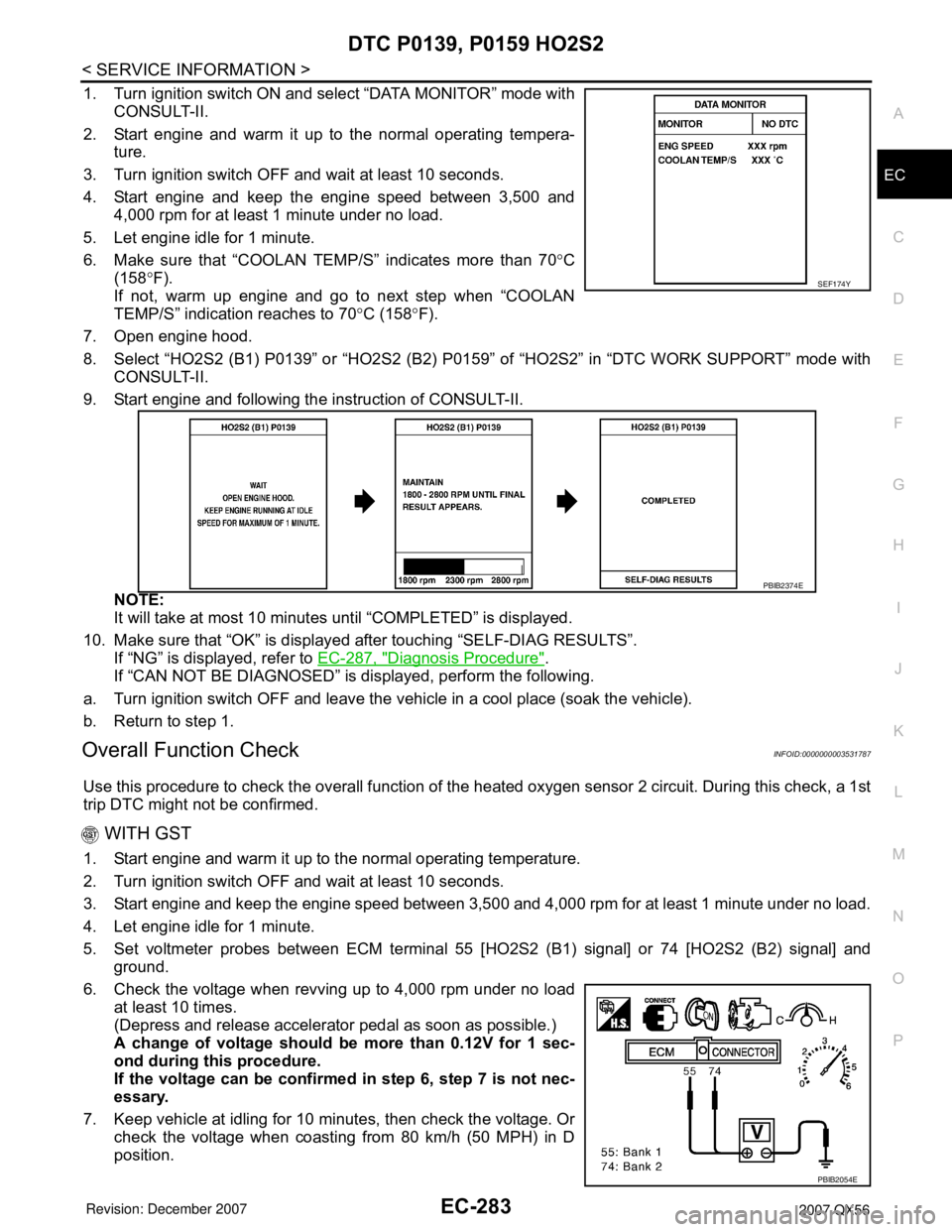
1. Turn ignition switch ON and select “DATA MONITOR” mode with
CONSULT-II.
2. Start engine and warm it up to the normal operating tempera-
ture.
3. Turn ignition switch OFF and wait at least 10 seconds.
4. Start engine and keep the engine speed between 3,500 and
4,000 rpm for at least 1 minute under no load.
5. Let engine idle for 1 minute.
6. Make sure that “COOLAN TEMP/S” indicates more than 70°C
(158°F).
If not, warm up engine and go to next step when “COOLAN
TEMP/S” indication reaches to 70°C (158°F).
7. Open engine hood.
8. Select “HO2S2 (B1) P0139” or “HO2S2 (B2) P0159” of “HO2S2” in “DTC WORK SUPPORT” mode with
CONSULT-II.
9. Start engine and following the instruction of CONSULT-II.
NOTE:
It will take at most 10 minutes until “COMPLETED” is displayed.
10. Make sure that “OK” is displayed after touching “SELF-DIAG RESULTS”.
If “NG” is displayed, refer to EC-287, "
Diagnosis Procedure".
If “CAN NOT BE DIAGNOSED” is displayed, perform the following.
a. Turn ignition switch OFF and leave the vehicle in a cool place (soak the vehicle).
b. Return to step 1.
Overall Function CheckINFOID:0000000003531787
Use this procedure to check the overall function of the heated oxygen sensor 2 circuit. During this check, a 1st
trip DTC might not be confirmed.
WITH GST
1. Start engine and warm it up to the normal operating temperature.
2. Turn ignition switch OFF and wait at least 10 seconds.
3. Start engine and keep the engine speed between 3,500 and 4,000 rpm for at least 1 minute under no load.
4. Let engine idle for 1 minute.
5. Set voltmeter probes between ECM terminal 55 [HO2S2 (B1) signal] or 74 [HO2S2 (B2) signal] and
ground.
6. Check the voltage when revving up to 4,000 rpm under no load
at least 10 times.
(Depress and release accelerator pedal as soon as possible.)
A change of voltage should be more than 0.12V for 1 sec-
ond during this procedure.
If the voltage can be confirmed in step 6, step 7 is not nec-
essary.
7. Keep vehicle at idling for 10 minutes, then check the voltage. Or
check the voltage when coasting from 80 km/h (50 MPH) in D
position.
SEF174Y
PBIB2374E
PBIB2054E