2007 INFINITI QX56 front door lock actuator
[x] Cancel search: front door lock actuatorPage 743 of 3061

BL-32
< SERVICE INFORMATION >
POWER DOOR LOCK SYSTEM
Front Door Lock Assembly LH (Actuator) Check
INFOID:0000000003532908
1.CHECK DOOR LOCK ACTUATOR SIGNAL
1. Turn ignition switch OFF.
2. Check voltage between BCM connector M20 terminals 59, 65
and ground.
OK or NG
OK >> GO TO 2.
NG >> Replace BCM. Refer to BCS-24, "
BCM".
2.CHECK DOOR LOCK ACTUATOR HARNESS
1. Disconnect BCM and front door lock assembly LH (actuator).
2. Check continuity between BCM connector M20 terminals 59, 65
and front door lock assembly LH (actuator) connector D14 termi-
nals 2, 3.
3. Check continuity between BCM connector M20 terminals 59, 65
and ground.
OK or NG
OK >> Replace front door lock assembly LH (actuator). Refer to BL-110.
NG >> Repair or replace harness.
Front Door Lock Actuator RH CheckINFOID:0000000003532909
1.CHECK FRONT DOOR LOCK ACTUATOR RH SIGNAL
1. Turn ignition switch OFF.
2. Check voltage between BCM connector M20 terminals 65, 66
and ground.
ConnectorTe r m i n a l s
ConditionVoltage (V)
(Approx.)
(+) (-)
M2059
GroundDriver door lock/unlock
switch is turned to UN-
LOCK0 → Battery voltage
65Driver door lock/unlock
switch is turned to LOCK0 → Battery voltage
LIIA1046E
Connector Terminals Connector Terminals Continuity
M2059
D142Yes
65 3 Yes
Connector Terminals Continuity
M2059
GroundNo
65 No
LIIA1574E
ConnectorTe r m i n a l s
ConditionVoltage (V)
(Approx.)
(+) (-)
M2065
GroundDoor lock/unlock switch is
turned to LOCK0 → Battery voltage
for 300 ms
66Door lock/unlock switch is
turned to UNLOCK0 → Battery voltage
for 300 ms
LIIA1048E
Page 744 of 3061

POWER DOOR LOCK SYSTEM
BL-33
< SERVICE INFORMATION >
C
D
E
F
G
H
J
K
L
MA
B
BL
N
O
P
OK or NG
OK >> GO TO 2.
NG >> Replace BCM. Refer to BCS-24, "
BCM".
2.CHECK FRONT DOOR LOCK ACTUATOR RH HARNESS
1. Disconnect BCM and front door lock actuator RH.
2. Check continuity between BCM connector M20 terminals 65, 66
and front door lock actuator RH D114 terminals 2, 3.
3. Check continuity between BCM connector M20 terminals 65, 66
and ground.
OK or NG
OK >> Replace front door lock actuator RH. Refer to BL-110.
NG >> Repair or replace harness.
Rear Door Lock Actuator RH/LH CheckINFOID:0000000003532910
1.CHECK DOOR LOCK ACTUATOR SIGNAL
1. Turn ignition switch OFF.
2. Check voltage between BCM connector M20 terminals 65, 66
and ground.
OK or NG
OK >> GO TO 2.
NG >> Replace BCM. Refer to BCS-24, "
BCM".
2.CHECK REAR DOOR LOCK ACTUATOR LH OR RH HARNESS
1. Disconnect BCM and each door lock actuator.
Terminals Continuity
65 3 Yes
66 2 Yes
Terminals Continuity
65
GroundNo
66 No
LIIA1479E
ConnectorTe r m i n a l s
ConditionVoltage (V)
(Approx.)
(+) (-)
M2065
GroundDoor lock/unlock switch
is turned to LOCK0 → Battery voltage
for 300 ms
66Door lock/unlock switch
is turned to UNLOCK0 → Battery voltage
for 300 ms
LIIA1048E
Page 746 of 3061

POWER DOOR LOCK SYSTEM
BL-35
< SERVICE INFORMATION >
C
D
E
F
G
H
J
K
L
MA
B
BL
N
O
P
2. Check continuity between glass hatch lock actuator connector
D711 terminal 1 and ground.
OK or NG
OK >> Replace glass hatch lock actuator. Refer to BL-114.
NG >> Repair or replace harness.
Front Door Lock Assembly LH (Key Cylinder Switch) CheckINFOID:0000000003532912
1.CHECK DOOR KEY CYLINDER SWITCH LH
With CONSULT-II
Check front door lock assembly LH (key cylinder switch) ("KEY CYL LK-SW") and ("KEY CYL UN-SW) in
DATA MONITOR mode with CONSULT–II. Refer to BL-24, "
CONSULT-II Function (BCM)".
• When key inserted in front key cylinder is turned to LOCK:
• When key inserted in front key cylinder is turned to UNLOCK:
Without CONSULT-II
Check voltage between main power window and door lock/unlock
switch connector D7 terminals 4, 6 and ground.
OK or NG
OK >> Front door lock assembly LH (key cylinder switch) signal is OK.
NG >> GO TO 2.
2.CHECK DOOR KEY CYLINDER SWITCH LH GROUND HARNESS
Terminals Continuity
1 Ground Yes
LIIA1940E
KEY CYL LK-SW : ON
KEY CYL UN-SW : ON
LIIA0188E
ConnectorTe r m i n a l s
ConditionVoltage (V)
(Approx.)
(+) (–)
D74
GroundNeutral/Unlock 5
Lock 0
6Neutral/Lock 5
Unlock 0
LIIA0566E
Page 823 of 3061

BL-112
< SERVICE INFORMATION >
FRONT DOOR LOCK
9. While pulling the outside handle bracket, slide it toward the rear
of vehicle to remove it and the door lock assembly.
10. Disconnect the door lock actuator electrical connector.
11. Separate the outside handle cable connection from the outside
handle bracket.
INSTALLATION
Installation in the reverse order of removal.
CAUTION:
To install each rod, be sure to rotate the rod holder until a click is felt.
Disassembly and AssemblyINFOID:0000000003532981
DOOR KEY CYLINDER ASSEMBLY
Remove the key cylinder escutcheon pawl and remove the door key cylinder.
PIIA3558E
PIIA5059E
PIIA4136E
Page 2034 of 3061

POWER WINDOW SYSTEM
GW-15
< SERVICE INFORMATION >
C
D
E
F
G
H
J
K
L
MA
B
GW
N
O
P
POWER WINDOW SYSTEM
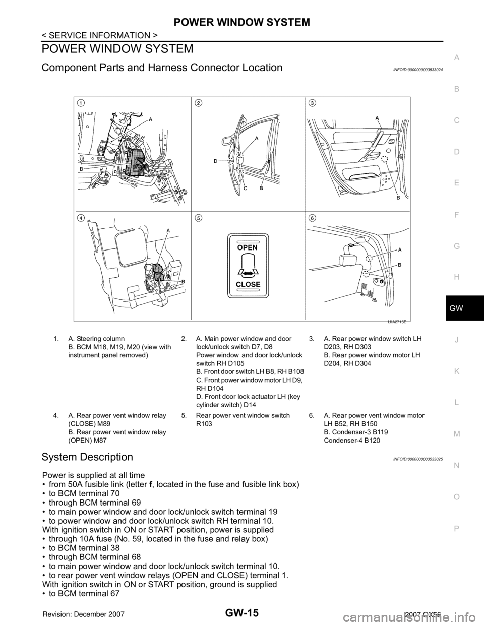
Component Parts and Harness Connector LocationINFOID:0000000003533024
System DescriptionINFOID:0000000003533025
Power is supplied at all time
• from 50A fusible link (letter f, located in the fuse and fusible link box)
• to BCM terminal 70
• through BCM terminal 69
• to main power window and door lock/unlock switch terminal 19
• to power window and door lock/unlock switch RH terminal 10.
With ignition switch in ON or START position, power is supplied
• through 10A fuse (No. 59, located in the fuse and relay box)
• to BCM terminal 38
• through BCM terminal 68
• to main power window and door lock/unlock switch terminal 10.
• to rear power vent window relays (OPEN and CLOSE) terminal 1.
With ignition switch in ON or START position, ground is supplied
• to BCM terminal 67
1. A. Steering column
B. BCM M18, M19, M20 (view with
instrument panel removed)2. A. Main power window and door
lock/unlock switch D7, D8
Power window and door lock/unlock
switch RH D105
B. Front door switch LH B8, RH B108
C. Front power window motor LH D9,
RH D104
D. Front door lock actuator LH (key
cylinder switch) D143. A. Rear power window switch LH
D203, RH D303
B. Rear power window motor LH
D204, RH D304
4. A. Rear power vent window relay
(CLOSE) M89
B. Rear power vent window relay
(OPEN) M875. Rear power vent window switch
R1036. A. Rear power vent window motor
LH B52, RH B150
B. Condenser-3 B119
Condenser-4 B120
LIIA2715E
Page 2108 of 3061

IDX-4
ALPHABETICAL INDEX
Duct and grilles .............................................. ATC-170
DVD - Wiring Diagram ....................................... AV-75
DVD Entertainment System ............................... AV-72
DVD Player ........................................................ AV-73
E
ECM input/output signal ..................... EC-109
, EC-133
ECM power supply ............................. EC-150, EC-475
ECM relay ........................................................ EC-150
ECM/PW - Wiring diagram ............................... EC-476
ECTS - Wiring diagram .................................... EC-220
Electric sunroof .................................................. RF-10
Electric throttle control actuator ......... EC-595, EC-606
Electrical load signal circuit .............................. EC-657
Electrical units location ...................................... PG-65
Electronic ignition (EI) system ........................... EC-27
Engine control circuit diagram ......................... EC-107
Engine control component parts location ........... EC-98
Engine control module (ECM) .......................... EC-479
Engine control system diagram ......................... EC-24
Engine coolant .................................................. CO-10
Engine coolant temperature sensor (ECTS) ... EC-218,
EC-231
Engine fail-safe system ...................................... EC-93
Engine oil ............................................................. LU-8
Engine oil filter replacement ............................. MA-17
Engine oil precautions .......................................... GI-7
Engine oil replacement ..................................... MA-17
Engine removal ................................................. EM-74
Engine room cover ............................................ EM-12
Engine serial number .......................................... GI-50
ETC1 - Wiring diagram .................................... EC-596
ETC2 - Wiring diagram .................................... EC-591
ETC3 - Wiring diagram .................................... EC-602
EVAP canister .................................................... EC-36
EVAP canister purge volume control solenoid valve ....
EC-395
, EC-403
EVAP canister vent control valve ....... EC-410, EC-417
EVAP control system (small leak) diagnosis .. EC-387,
EC-441
, EC-449
EVAP control system pressure sensor .... EC-424, EC-
427, EC-433
EVAP control system purge flow monitoring diagnosis
EC-382
EVAP vapor lines inspection ............................. MA-20
Evaporative emission (EVAP) system ............... EC-33
Evaporator ..................................................... ATC-186
Exhaust manifold .............................................. EM-21
Exhaust system ................................................... EX-3
Exhaust system inspection .................................. EX-3
Expansion valve ............................................. ATC-188
F
F/FOG - Wiring diagram ..................................... LT-56
F/PUMP - Wiring diagram ................................ EC-666
Final drive pre-inspection ................................. FFD-15
Final drive removal and installation .. FFD-12, RFD-13
Flow charts .......................................................... GI-27
Fluid temperature sensor (A/T) ........................ AT-123
Fluids ................................................................ MA-11
Fluorescent leak detector .............................. ATC-189
Fog lamp, front ................................................... LT-54
Fog lamp, front, removal and installation ........... LT-62
Foot lamp ......................................................... LT-111
Freeze frame data ............................... EC-55, EC-121
Front brake solenoid valve ................. AT-139, AT-141
Front bumper ...................................................... EI-13
Front case (Transfer) .......................... TF-149, TF-176
Front combination lamp removal and installation LT-25
Front door ............................. BL-117, BL-121, GW-62
Front Door Trim ................................................... EI-32
Front drive shaft (Transfer) ................. TF-149, TF-176
Front fog lamp .................................................... LT-54
Front fog lamp removal and installation ............. LT-62
Front passenger air bag .................................. SRS-43
Front seat ........................................................... SE-89
Front seat belt ...................................................... SB-3
Front seat belt pre-tensioner ............... SRS-3, SRS-50
Front washer ...................................................... WW-4
Front wiper ......................................................... WW-4
FTS - Wiring diagram ....................................... AT-124
FTTS - Wiring diagram ...................... EC-334, EC-339
Fuel cut control (at no load high engine speed) EC-28
Fuel filter replacement ......................................... FL-5
Fuel gauge ............................................................ DI-5
Fuel injection system (Bank 1) .......... EC-311, EC-322
Fuel injection system (Bank 2) .......... EC-311, EC-322
Fuel injector .................................................... EC-659
Fuel injector and fuel tube ................................. EM-31
Fuel level sensor ................. EC-458, EC-460, EC-462
Fuel line inspection .............................................. FL-4
Fuel precautions ................................................... GI-5
Fuel pressure check .......................................... EC-82
Fuel pressure release ....................................... EC-82
Fuel pump ....................................................... EC-665
Fuel pump and gauge .......................................... FL-5
Fuel system .......................................................... FL-4
Fuel tank ............................................................ FL-10
Fuel tank temperature sensor ........... EC-332, EC-338
Fuel tank vacuum relief valve ........................... EC-36
FUELB1 - Wiring diagram ................. EC-313, EC-324
FUELB2 - Wiring diagram ................. EC-315, EC-326
Fuse ...................................................... PG-17, PG-77
Fuse and fusible link box .................................. PG-77
Fuse block ......................................................... PG-76
Fusible link ............................................ PG-17, PG-77
G
Garage jack and safety stand ............................. GI-42
Gauges ................................................................. DI-5
Generator .......................................................... SC-17
Generic scan tool (GST) ................................. EC-131
Glass ...................................... GW-11, GW-62, GW-65
Glove box lamp ................................................ LT-131
GPS antenna ..................................................... AV-82