2007 INFINITI QX56 Head light
[x] Cancel search: Head lightPage 766 of 3061

REMOTE KEYLESS ENTRY SYSTEM
BL-55
< SERVICE INFORMATION >
C
D
E
F
G
H
J
K
L
MA
B
BL
N
O
P
Check voltage between IPDM E/R connector E122 terminal 45 and
ground.
OK or NG
OK >> Replace IPDM E/R.
NG >> GO TO 2.
2.CHECK IPDM E/R INPUT VOLTAGE
1. Turn ignition switch OFF.
2. Disconnect IPDM E/R and horn relay.
3. Check continuity between IPDM E/R connector E122 terminal
45 and horn relay connector H-1 terminal 1.
4. Check continuity between IPDM E/R connector E122 terminal
45 and ground.
OK or NG
OK >> Further inspection is necessary. Refer to BL-47, "Trou-
ble Diagnosis".
NG >> Repair or replace harness
Check Hazard FunctionINFOID:0000000003532932
1.CHECK HAZARD WARNING LAMP
Does hazard indicator flash with hazard switch?
Ye s o r N o
Yes >> Hazard warning lamp circuit is OK.
No >> Check hazard indicator. Refer to LT- 5 7
.
Check Horn FunctionINFOID:0000000003532933
First, perform the "SELF-DIAG RESULTS" in "BCM" with CONSULT-II, then perform the trouble diagnosis of
malfunction system indicated in "SELF-DIAG RESULTS" of "BCM".
1.CHECK HORN FUNCTION
Does horn sound with horn switch?
Ye s o r N o
Yes >> Horn circuit is OK.
No >> Check horn circuit. Refer to WW-43
.
Check Headlamp FunctionINFOID:0000000003532934
First, perform the "SELF-DIAG RESULTS" in "BCM" with CONSULT-II, then perform the trouble diagnosis of
malfunction system indicated in "SELF-DIAG RESULTS" of "BCM".
1.CHECK HEADLAMP OPERATION
Does headlamp come on when turning lighting switch ON?
Ye s o r N o
Yes >> Headlamp operation circuit is OK.
No >> Check headlamp circuit. Refer to LT- 5
.
ConnectorTe r m i n a l s
Voltage (V)
(Approx.)
(+) (–)
E122 45 Ground Battery voltage
LIIA1053E
45 - 1 : Continuity should exist.
45 - Ground : Continuity should not exist.
WIIA0679E
Page 790 of 3061

VEHICLE SECURITY (THEFT WARNING) SYSTEM
BL-79
< SERVICE INFORMATION >
C
D
E
F
G
H
J
K
L
MA
B
BL
N
O
P
Check continuity between main power window and door lock/unlock
switch connector (A) D7 terminals 4, 6 and front door lock assembly
LH (key cylinder switch) connector (B) D14 terminals 1, 6 and body
ground.
OK or NG
OK >> Replace main power window and door lock/unlock switch.
NG >> Repair or replace harness.
Vehicle Security Horn Alarm CheckINFOID:0000000003532953
1.CHECK HORN OPERATION
Check if horn sounds with horn switch.
Does horn operate?
YES >> Check harness for open or short between IPDM E/R and horn relay.
NO >> Check horn circuit. Refer to WW-43
.
Vehicle Security Headlamp Alarm CheckINFOID:0000000003532954
1.CHECK VEHICLE SECURITY HEADLAMP ALARM OPERATION
Check if headlamps operate with lighting switch.
Do headlamps come on when turning switch ON?
YES >> Headlamp alarm is OK.
NO >> Check headlamp system. Refer to LT- 5
or LT- 2 4.
Door Lock/Unlock Switch CheckINFOID:0000000003532955
1.CHECK DOOR LOCK/UNLOCK SWITCH INPUT SIGNAL
Check if power door lock operates with door lock/unlock switch.
Do doors lock/unlock when using each door lock/unlock switch?
YES >> Door lock/unlock switch is OK.
NO >> Refer to "Door Lock/Unlock Switch Check ".
Connector Terminals Connector Terminals Continuity
A: Main
power win-
dow and
door lock/
unlock
switch4 B: Front
door lock
assembly
LH (key
cylinder
switch)1Yes
66Yes
4, 6 Ground No
WIIA0756E
Page 1048 of 3061

WARNING CHIME
DI-37
< SERVICE INFORMATION >
C
D
E
F
G
H
I
J
L
MA
B
DI
N
O
P
• to key switch and key lock solenoid terminal 3.
With ignition switch in ON or START position, power is supplied
• through 10A fuse (No. 59, located in the fuse and relay box)
• to BCM terminal 38.
Ground is supplied
• to BCM terminal 67
• through body grounds M57, M61, and M79.
NOTE:
When ignition key warning chime, light warning chime, and seat belt warning chime are required at the same
time, the priorities for each chime are the following.
1. Light warning chime
2. Ignition key warning chime
3. Seat belt warning chime
IGNITION KEY WARNING CHIME
With the key inserted in the ignition switch, the ignition switch in OFF position, and the driver's door open, the
warning chime will sound.
Power is supplied
• through key switch and key lock solenoid terminal 4
• to BCM terminal 37.
Ground is supplied
• to BCM terminal 47
• through front door switch LH terminal 2.
Front door switch LH is case grounded.
BCM detects key inserted into the ignition switch, and sends key warning signal to combination meter via CAN
communication lines. When the combination meter receives key warning signal, it sounds warning chime.
LIGHT WARNING CHIME
With the key removed from the ignition switch, the driver's door open, and the lighting switch (part of the com-
bination switch) in 1st or 2nd position, the warning chime will sound. [Except when headlamp battery saver
control operates (5 minutes after ignition switch is turned to OFF or ACC position) and headlamps do not illu-
minate.]
Signal is supplied
• from combination switch (lighting switch) terminals 1, 2, 3, 4, 5, 6, 7, 8, 9 and 10
• to BCM terminals 2, 3, 4, 5, 6, 32, 33, 34, 35 and 36.
NOTE:
BCM detected lighting switch in 1st or 2nd position. Refer to LT-72, "
Combination Switch Reading Function".
Ground is supplied
• to BCM terminal 47
• through front door switch LH terminal 2.
Front door switch LH is case grounded.
BCM detects headlamps are illuminated, and sends light warning signal to combination meter CAN communi-
cation lines. When the combination meter receives light warning signal, it sounds warning chime.
SEAT BELT WARNING CHIME
When the ignition switch is turned ON with the seat belt unfastened [seat belt buckle pre-tensioner assembly
LH (seat belt buckle switch) unfastened], warning chime will sound for approximately 6 seconds.
Ground is supplied
• to combination meter terminal 27
• through seat belt buckle pre-tensioner assembly LH (seat belt buckle switch) terminal 4.
Seat belt buckle pre-tensioner assembly LH (seat belt buckle switch) terminal 3 is grounded through body
grounds B7 and B19.
The combination meter sends seat belt buckle switch LH unfastened signal to BCM via CAN communication
line.
BCM receives seat belt buckle pre-tensioner assembly LH (seat belt buckle switch) unfastened signal from
combination meter via CAN communication line, and sends seat belt warning signal to the combination meter
via CAN communication line. When the combination meter receives the seat belt warning signal, it sounds the
warning chime. The BCM controls the (6 second) duration of the seat belt warning chime.
CAN Communication System DescriptionINFOID:0000000003533512
Refer to LAN-4.
Page 1161 of 3061

EC-78
< SERVICE INFORMATION >
BASIC SERVICE PROCEDURE
3. Turn ignition switch OFF wait at least 10 seconds.
Make sure that throttle valve moves during above 10 seconds by confirming the operating sound.
Idle Air Volume LearningINFOID:0000000003531615
DESCRIPTION
Idle Air Volume Learning is an operation to learn the idle air volume that keeps each engine within the specific
range. It must be performed under any of the following conditions:
• Each time electric throttle control actuator or ECM is replaced.
• Idle speed or ignition timing is out of specification.
PREPARATION
Before performing Idle Air Volume Learning, make sure that all of the following conditions are satisfied.
Learning will be cancelled if any of the following conditions are missed for even a moment.
• Battery voltage: More than 12.9V (At idle)
• Engine coolant temperature: 70 - 100°C (158 - 212°F)
• Park/Neutral position (PNP) switch: ON
• Electric load switch: OFF
(Air conditioner, headlamp, rear window defogger)
On vehicles equipped with daytime light systems, if the parking brake is applied before the engine is
start the headlamp will not be illuminated.
• Steering wheel: Neutral (Straight-ahead position)
• Vehicle speed: Stopped
• Transmission: Warmed-up
- With CONSULT-II: Drive vehicle until “ATF TEMP SE 1” in “DATA MONITOR” mode of “A/T” system indi-
cates less than 0.9V.
- Without CONSULT-II: Drive vehicle for 10 minutes.
OPERATION PROCEDURE
With CONSULT-II
1. Perform EC-77, "Accelerator Pedal Released Position Learning" .
2. Perform EC-77, "
Throttle Valve Closed Position Learning" .
3. Start engine and warm it up to normal operating temperature.
4. Check that all items listed under the topic PREPARATION (previously mentioned) are in good order.
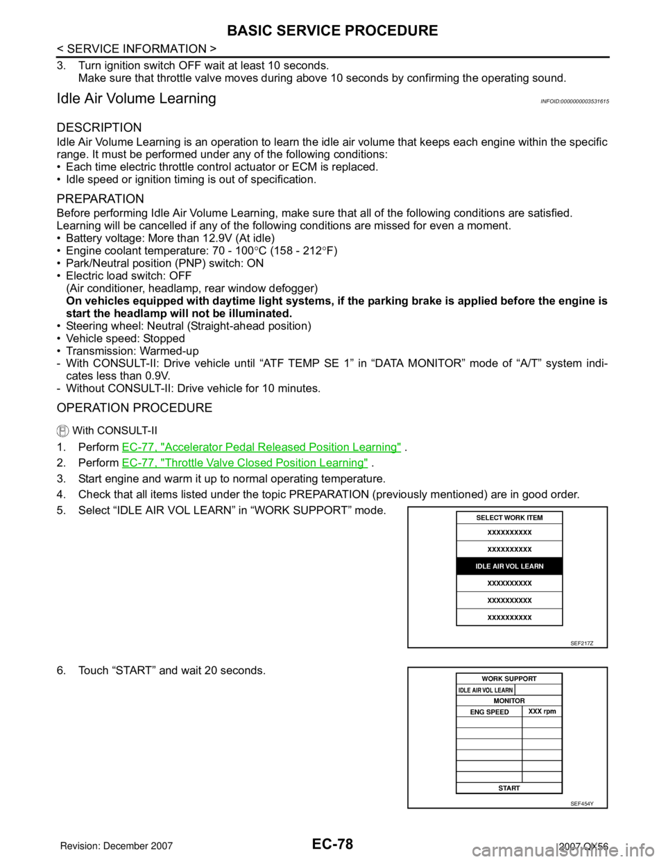
5. Select “IDLE AIR VOL LEARN” in “WORK SUPPORT” mode.
6. Touch “START” and wait 20 seconds.
SEF217Z
SEF454Y
Page 1212 of 3061

TROUBLE DIAGNOSIS - SPECIFICATION VALUE
EC-129
< SERVICE INFORMATION >
C
D
E
F
G
H
I
J
K
L
MA
EC
N
P O
TROUBLE DIAGNOSIS - SPECIFICATION VALUE
DescriptionINFOID:0000000003531630
The specification (SP) value indicates the tolerance of the value that is displayed in “DATA MONITOR (SPEC)”
mode of CONSULT-II during normal operation of the Engine Control System. When the value in “DATA MONI-
TOR (SPEC)” mode is within the SP value, the Engine Control System is confirmed OK. When the value in
“DATA MONITOR (SPEC)” mode is NOT within the SP value, the Engine Control System may have one or
more malfunctions.
The SP value is used to detect malfunctions that may affect the Engine Control System, but will not light the
MIL.
The SP value will be displayed for the following three items:
• B/FUEL SCHDL (The fuel injection pulse width programmed into ECM prior to any learned on board correc-
tion)
• A/F ALPHA-B1/B2 (The mean value of air-fuel ratio feedback correction factor per cycle)
• MAS A/F SE-B1 (The signal voltage of the mass air flow sensor)
Testing ConditionINFOID:0000000003531631
• Vehicle driven distance: More than 5,000 km (3,107 miles)
• Barometric pressure: 98.3 - 104.3 kPa (1.003 - 1.064 kg/cm
2 , 14.25 - 15.12 psi)
• Atmospheric temperature: 20 - 30°C (68 - 86°F)
• Engine coolant temperature: 75 - 95°C (167 - 203°F)
• Engine speed: Idle
• Transmission: Warmed-up
- After the engine is warmed up to normal operating temperature, drive vehicle until “ATF TEMP SE 1” (A/T
fluid temperature sensor signal) indicates more than 60°C (140°F).
• Electrical load: Not applied
- Rear window defogger switch, air conditioner switch, lighting switch are OFF. Steering wheel is straight
ahead.
Inspection ProcedureINFOID:0000000003531632
NOTE:
Perform “DATA MONITOR (SPEC)” mode in maximum scale display.
1. Perform EC-71, "
Basic Inspection" .
2. Confirm that the testing conditions indicated above are met.
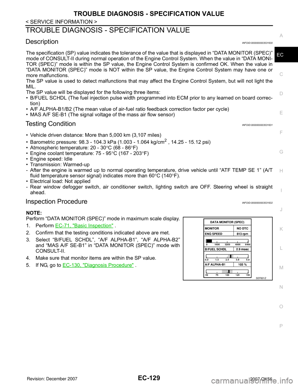
3. Select “B/FUEL SCHDL”, “A/F ALPHA-B1”, “A/F ALPHA-B2”
and “MAS A/F SE-B1” in “DATA MONITOR (SPEC)” mode with
CONSULT-II.
4. Make sure that monitor items are within the SP value.
5. If NG, go to EC-130, "
Diagnosis Procedure" .
SEF601Z
Page 1689 of 3061

EC-606
< SERVICE INFORMATION >
ELECTRICAL LOAD SIGNAL
ELECTRICAL LOAD SIGNAL
DescriptionINFOID:0000000003532157
The electrical load signal (Headlamp switch signal, rear window defogger switch signal, etc.) is transferred
through the CAN communication line from BCM to ECM via IPDM E/R.
CONSULT-II Reference Value in Data Monitor ModeINFOID:0000000003532158
Specification data are reference values.
Diagnosis ProcedureINFOID:0000000003532159
1.CHECK LOAD SIGNAL CIRCUIT OVERALL FUNCTION-I
1. Turn ignition switch ON.
2. Connect CONSULT-II and select “DATA MONITOR” mode.
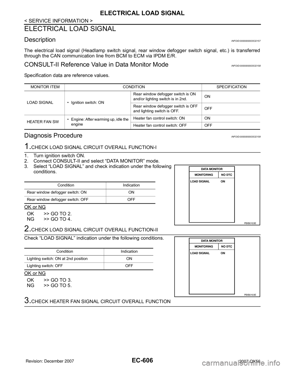
3. Select “LOAD SIGNAL” and check indication under the following
conditions.
OK or NG
OK >> GO TO 2.
NG >> GO TO 4.
2.CHECK LOAD SIGNAL CIRCUIT OVERALL FUNCTION-II
Check “LOAD SIGNAL” indication under the following conditions.
OK or NG
OK >> GO TO 3.
NG >> GO TO 5.
3.CHECK HEATER FAN SIGNAL CIRCUIT OVERALL FUNCTION
MONITOR ITEM CONDITION SPECIFICATION
LOAD SIGNAL • Ignition switch: ONRear window defogger switch is ON
and/or lighting switch is in 2nd.ON
Rear window defogger switch is OFF
and lighting switch is OFF.OFF
HEATER FAN SW• Engine: After warming up, idle the
engineHeater fan control switch: ON ON
Heater fan control switch: OFF OFF
Condition Indication
Rear window defogger switch: ON ON
Rear window defogger switch: OFF OFF
PBIB0103E
Condition Indication
Lighting switch: ON at 2nd position ON
Lighting switch: OFF OFF
PBIB0103E
Page 1728 of 3061

SERVICE DATA AND SPECIFICATIONS (SDS)
EC-645
< SERVICE INFORMATION >
C
D
E
F
G
H
I
J
K
L
MA
EC
N
P O
SERVICE DATA AND SPECIFICATIONS (SDS)
Fuel PressureINFOID:0000000003532187
Idle Speed and Ignition TimingINFOID:0000000003532188
*: Under the following conditions:
• Air conditioner switch: OFF
• Electric load: OFF (Lights and heater fan)
• Steering wheel: Kept in straight-ahead position
Calculated Load ValueINFOID:0000000003532189
Mass Air Flow SensorINFOID:0000000003532190
*: Engine is warmed up to normal operating temperature and running under no load.
Intake Air Temperature SensorINFOID:0000000003532191
Engine Coolant Temperature SensorINFOID:0000000003532192
A/F Sensor 1 HeaterINFOID:0000000003532193
Heated Oxygen sensor 2 HeaterINFOID:0000000003532194
Fuel pressure at idling kPa (kg/cm2, psi)Approximately 350 (3.57, 51)
Target idle speed No-load* (in P or N position) 650±50 rpm
Air conditioner: ON In P or N position 700 rpm or more
Ignition timing In P or N position 15° ± 5° BTDC
Condition Calculated load value % (Using CONSULT-II or GST)
At idle14.0 - 33.0
At 2,500 rpm12.0 - 25.0
Supply voltage Battery voltage (11 - 14V)
Output voltage at idle1.0 - 1.3V*
Mass air flow (Using CONSULT-II or GST)3.0 - 9.0 g·m/sec at idle*
9.0 - 28.0 g·m/sec at 2,500 rpm*
Temperature °C (°F) Resistance kΩ
25 (77)1.800 - 2.200
Temperature °C (°F) Resistance kΩ
20 (68)2.1 - 2.9
50 (122)0.68 - 1.00
90 (194)0.236 - 0.260
Resistance [at 25°C (77°F)] 1.8 - 2.44Ω
Resistance [at 25°C (77°F)] 8 - 10Ω
Page 1736 of 3061

SQUEAK AND RATTLE TROUBLE DIAGNOSIS
EI-7
< SERVICE INFORMATION >
C
D
E
F
G
H
J
K
L
MA
B
EI
N
O
P
Most of these incidents can be repaired by adjusting, securing or insulating the item(s) or component(s) caus-
ing the noise.
SUNROOF/HEADLINING
Noises in the sunroof/headlining area can often be traced to one of the following:
1. Sunroof lid, rail, linkage or seals making a rattle or light knocking noise
2. Sun visor shaft shaking in the holder
3. Front or rear windshield touching headliner and squeaking
Again, pressing on the components to stop the noise while duplicating the conditions can isolate most of these
incidents. Repairs usually consist of insulating with felt cloth tape.
OVERHEAD CONSOLE (FRONT AND REAR)
Overhead console noises are often caused by the console panel clips not being engaged correctly. Most of
these incidents are repaired by pushing up on the console at the clip locations until the clips engage.
In addition look for:
1. Loose harness or harness connectors.
2. Front console map/reading lamp lens loose.
3. Loose screws at console attachment points.
SEATS
When isolating seat noise it's important to note the position the seat is in and the load placed on the seat when
the noise is present. These conditions should be duplicated when verifying and isolating the cause of the
noise.
Cause of seat noise include:
1. Headrest rods and holder
2. A squeak between the seat pad cushion and frame
3. The rear seatback lock and bracket
These noises can be isolated by moving or pressing on the suspected components while duplicating the con-
ditions under which the noise occurs. Most of these incidents can be repaired by repositioning the component
or applying urethane tape to the contact area.
UNDERHOOD
Some interior noise may be caused by components under the hood or on the engine wall. The noise is then
transmitted into the passenger compartment.
Causes of transmitted underhood noise include:
1. Any component installed to the engine wall
2. Components that pass through the engine wall
3. Engine wall mounts and connectors
4. Loose radiator installation pins
5. Hood bumpers out of adjustment
6. Hood striker out of adjustment
These noises can be difficult to isolate since they cannot be reached from the interior of the vehicle. The best
method is to secure, move or insulate one component at a time and test drive the vehicle. Also, engine RPM
or load can be changed to isolate the noise. Repairs can usually be made by moving, adjusting, securing, or
insulating the component causing the noise.