2007 INFINITI QX56 engine oil
[x] Cancel search: engine oilPage 1854 of 3061
EM-84
< SERVICE INFORMATION >
CYLINDER BLOCK
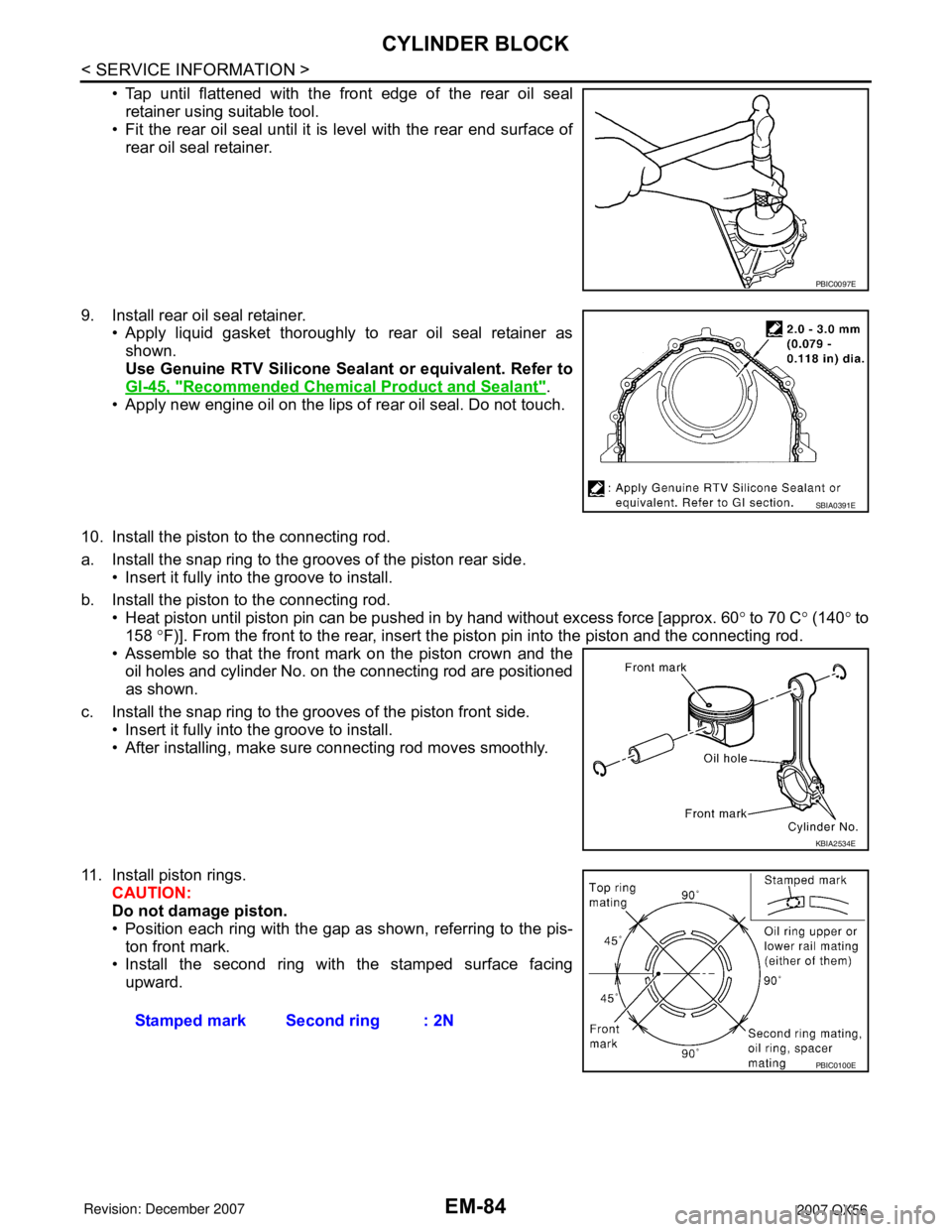
• Tap until flattened with the front edge of the rear oil seal
retainer using suitable tool.
• Fit the rear oil seal until it is level with the rear end surface of
rear oil seal retainer.
9. Install rear oil seal retainer.
• Apply liquid gasket thoroughly to rear oil seal retainer as
shown.
Use Genuine RTV Silicone Sealant or equivalent. Refer to
GI-45, "
Recommended Chemical Product and Sealant".
• Apply new engine oil on the lips of rear oil seal. Do not touch.
10. Install the piston to the connecting rod.
a. Install the snap ring to the grooves of the piston rear side.
• Insert it fully into the groove to install.
b. Install the piston to the connecting rod.
• Heat piston until piston pin can be pushed in by hand without excess force [approx. 60° to 70 C° (140° to
158 °F)]. From the front to the rear, insert the piston pin into the piston and the connecting rod.
• Assemble so that the front mark on the piston crown and the
oil holes and cylinder No. on the connecting rod are positioned
as shown.
c. Install the snap ring to the grooves of the piston front side.
• Insert it fully into the groove to install.
• After installing, make sure connecting rod moves smoothly.
11. Install piston rings.
CAUTION:
Do not damage piston.
• Position each ring with the gap as shown, referring to the pis-
ton front mark.
• Install the second ring with the stamped surface facing
upward.
PBIC0097E
SBIA0391E
KBIA2534E
Stamped mark Second ring : 2N
PBIC0100E
Page 1855 of 3061
CYLINDER BLOCK
EM-85
< SERVICE INFORMATION >
C
D
E
F
G
H
I
J
K
L
MA
EM
N
P O
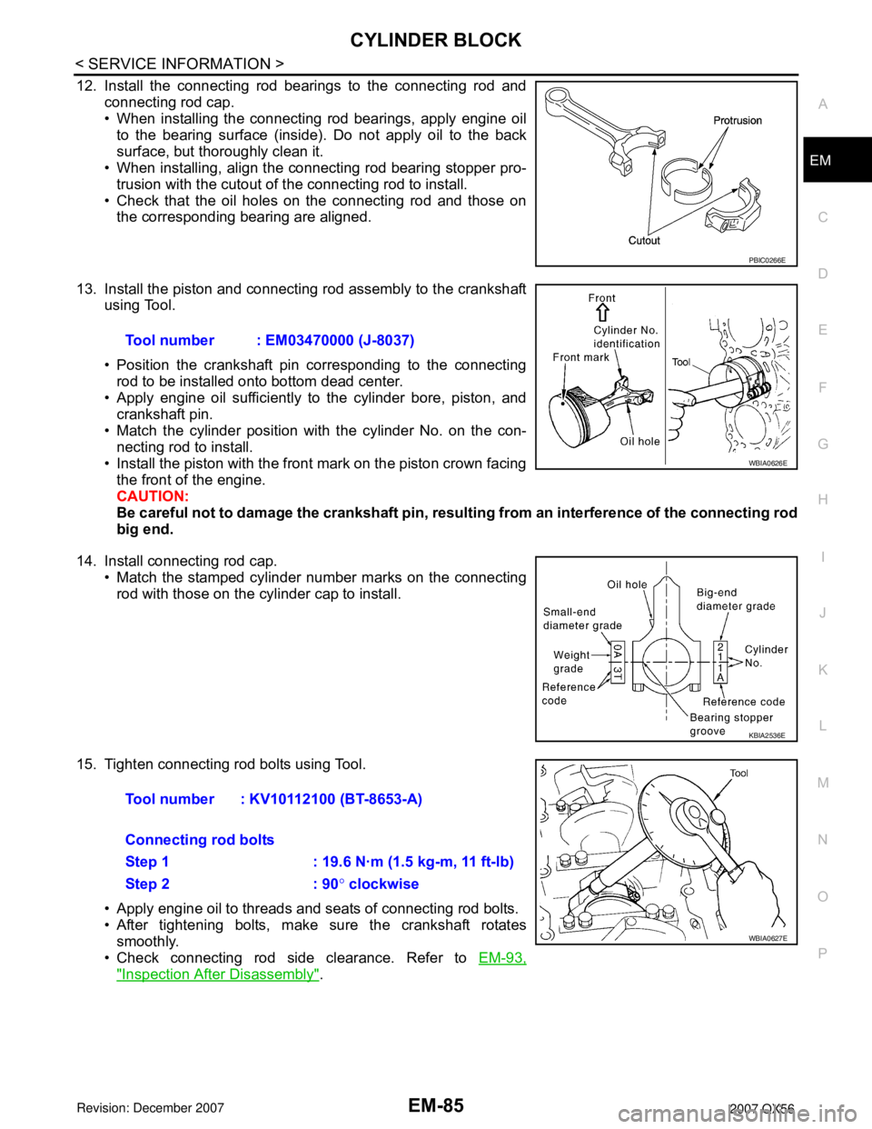
12. Install the connecting rod bearings to the connecting rod and
connecting rod cap.
• When installing the connecting rod bearings, apply engine oil
to the bearing surface (inside). Do not apply oil to the back
surface, but thoroughly clean it.
• When installing, align the connecting rod bearing stopper pro-
trusion with the cutout of the connecting rod to install.
• Check that the oil holes on the connecting rod and those on
the corresponding bearing are aligned.
13. Install the piston and connecting rod assembly to the crankshaft
using Tool.
• Position the crankshaft pin corresponding to the connecting
rod to be installed onto bottom dead center.
• Apply engine oil sufficiently to the cylinder bore, piston, and
crankshaft pin.
• Match the cylinder position with the cylinder No. on the con-
necting rod to install.
• Install the piston with the front mark on the piston crown facing
the front of the engine.
CAUTION:
Be careful not to damage the crankshaft pin, resulting from an interference of the connecting rod
big end.
14. Install connecting rod cap.
• Match the stamped cylinder number marks on the connecting
rod with those on the cylinder cap to install.
15. Tighten connecting rod bolts using Tool.
• Apply engine oil to threads and seats of connecting rod bolts.
• After tightening bolts, make sure the crankshaft rotates
smoothly.
• Check connecting rod side clearance. Refer to EM-93,
"Inspection After Disassembly".
PBIC0266E
Tool number : EM03470000 (J-8037)
WBIA0626E
KBIA2536E
Tool number : KV10112100 (BT-8653-A)
Connecting rod bolts
Step 1 : 19.6 N·m (1.5 kg-m, 11 ft-lb)
Step 2 : 90° clockwise
WBIA0627E
Page 1893 of 3061
DRIVE SHAFT
FAX-7
< SERVICE INFORMATION >
C
E
F
G
H
I
J
K
L
MA
B
FA X
N
O
P
DRIVE SHAFT
Removal and InstallationINFOID:0000000003532616
REMOVAL
1. Remove wheel and tire using power tool.
2. Remove engine under cover using power tool.
3. Remove wheel sensor harness from mount on knuckle.
CAUTION:
Do not pull on wheel sensor harness.
4. Without disassembling the hydraulic lines, remove brake caliper using power tool. Reposition it aside with
wire. Refer to BR-19, "
Removal and Installation of Brake Caliper and Disc Rotor" .
NOTE:
Avoid depressing brake pedal while brake caliper is removed.
5. Remove coil spring and shock absorber assembly using power tool. Refer to FSU-10, "
Removal and
Installation" .
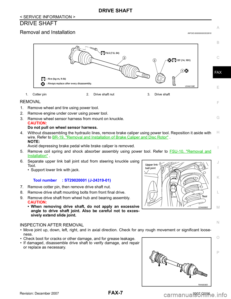
6. Separate upper link ball joint stud from steering knuckle using
Tool.
• Support lower link with jack.
7. Remove cotter pin, then remove drive shaft nut.
8. Remove drive shaft mounting bolts from front final drive.
9. Remove drive shaft from wheel hub and bearing assembly.
CAUTION:
• When removing drive shaft, do not apply an excessive
angle to drive shaft joint. Also be careful not to exces-
sively extend slide joint.
INSPECTION AFTER REMOVAL
• Move joint up, down, left, right, and in axial direction. Check for any rough movement or significant loose-
ness.
• Check boot for cracks or other damage, and for grease leakage.
• If damaged, disassemble drive shaft to verify damage, and repair
or replace as necessary.
1. Cotter pin 2. Drive shaft nut 3. Drive shaft
LDIA0159E
Tool number : ST29020001 (J-24319-01)
LEIA0095E
RAA0030D
Page 1906 of 3061
DIFFERENTIAL GEAR OIL
FFD-7
< SERVICE INFORMATION >
C
E
F
G
H
I
J
K
L
MA
B
FFD
N
O
P
DIFFERENTIAL GEAR OIL
Changing Differential Gear OilINFOID:0000000003532588
DRAINING
1. Stop the engine.
2. Remove the drain plug from the front final drive assembly to drain the differential gear oil.
3. Install the drain plug with sealant applied on the threads to the front final drive assembly. Tighten to the
specified torque. Refer to FFD-13, "
Disassembly and Assembly".
• Use High Performance Thread Sealant or equivalent. Refer to GI-45, "
Recommended Chemical Product
and Sealant".
FILLING
1. Remove the filler plug from the front final drive assembly.
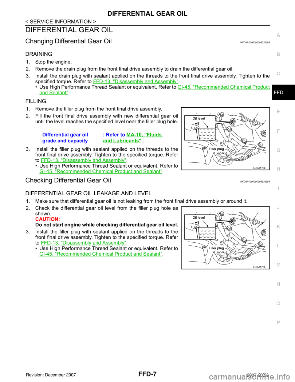
2. Fill the front final drive assembly with new differential gear oil
until the level reaches the specified level near the filler plug hole.
3. Install the filler plug with sealant applied on the threads to the
front final drive assembly. Tighten to the specified torque. Refer
to FFD-13, "
Disassembly and Assembly".
• Use High Performance Thread Sealant or equivalent. Refer to
GI-45, "
Recommended Chemical Product and Sealant".
Checking Differential Gear OilINFOID:0000000003532589
DIFFERENTIAL GEAR OIL LEAKAGE AND LEVEL
1. Make sure that differential gear oil is not leaking from the front final drive assembly or around it.
2. Check the differential gear oil level from the filler plug hole as
shown.
CAUTION:
Do not start engine while checking differential gear oil level.
3. Install the filler plug with sealant applied on the threads to the
front final drive assembly. Tighten to the specified torque. Refer
to FFD-13, "
Disassembly and Assembly".
• Use High Performance Thread Sealant or equivalent. Refer to
GI-45, "
Recommended Chemical Product and Sealant". Differential gear oil
grade and capacity: Refer to MA-10, "
Fluids
and Lubricants".
LDIA0176E
LDIA0176E
Page 1948 of 3061
FSU-2
< SERVICE INFORMATION >
PRECAUTIONS
SERVICE INFORMATION
PRECAUTIONS
PrecautionINFOID:0000000003532631
• When installing the rubber bushings, the final tightening must be done under unladen condition and with the
tires on level ground. Oil will shorten the life of the rubber bushings, so wipe off any spilled oil immediately.
• Unladen condition means the fuel tank, engine coolant and lubricants are at the full specification. The spare
tire, jack, hand tools, and mats are in their designated positions.
• After installing suspension components, check the wheel alignment.
• Lock nuts are not reusable. Always use new lock nuts for installation. New lock nuts are pre-oiled, do not
apply any additional lubrication.
Page 1965 of 3061
SERVICE DATA AND SPECIFICATIONS (SDS)
FSU-19
< SERVICE INFORMATION >
C
D
F
G
H
I
J
K
L
MA
B
FSU
N
O
P
SERVICE DATA AND SPECIFICATIONS (SDS)
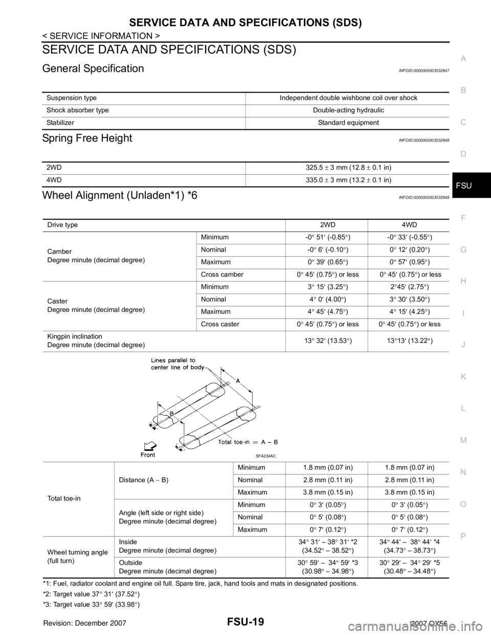
General SpecificationINFOID:0000000003532647
Spring Free HeightINFOID:0000000003532648
Wheel Alignment (Unladen*1) *6INFOID:0000000003532649
*1: Fuel, radiator coolant and engine oil full. Spare tire, jack, hand tools and mats in designated positions.
*2: Target value 37° 31′ (37.52°)
*3: Target value 33° 59′ (33.98°) Suspension type Independent double wishbone coil over shock
Shock absorber type Double-acting hydraulic
StabilizerStandard equipment
2WD325.5 ± 3 mm (12.8 ± 0.1 in)
4WD335.0 ± 3 mm (13.2 ± 0.1 in)
Drive type2WD 4WD
Camber
Degree minute (decimal degree)Minimum -0° 51′ (-0.85°)-0° 33′ (-0.55°)
Nominal -0° 6′ (-0.10°)0° 12′ (0.20°)
Maximum 0° 39′ (0.65°)0° 57′ (0.95°)
Cross camber 0° 45′ (0.75°) or less 0° 45′ (0.75°) or less
Caster
Degree minute (decimal degree)Minimum 3° 15′ (3.25°)2°45′ (2.75°)
Nominal 4° 0′ (4.00°)3° 30′ (3.50°)
Maximum 4° 45′ (4.75°)4° 15′ (4.25°)
Cross caster 0° 45′
(0.75°) or less 0° 45′ (0.75°) or less
Kingpin inclination
Degree minute (decimal degree)13° 32′ (13.53°)13°13′ (13.22°)
Total toe-inDistance (A − B)Minimum 1.8 mm (0.07 in) 1.8 mm (0.07 in)
Nominal 2.8 mm (0.11 in) 2.8 mm (0.11 in)
Maximum 3.8 mm (0.15 in) 3.8 mm (0.15 in)
Angle (left side or right side)
Degree minute (decimal degree)Minimum 0° 3′ (0.05°)0° 3′ (0.05°)
Nominal 0° 5′ (0.08°)0° 5′ (0.08°)
Maximum 0° 7′ (0.12°)0° 7′ (0.12°)
Wheel turning angle
(full turn)Inside
Degree minute (decimal degree)34° 31′ – 38° 31′ *2
(34.52° – 38.52°)34° 44′ – 38° 44′ *4
(34.73° – 38.73
°)
Outside
Degree minute (decimal degree)30° 59′ – 34° 59′ *3
(30.98° – 34.98°)30° 29′ – 34° 29′ *5
(30.48° – 34.48°)
SFA234AC
Page 1966 of 3061
FSU-20
< SERVICE INFORMATION >
SERVICE DATA AND SPECIFICATIONS (SDS)
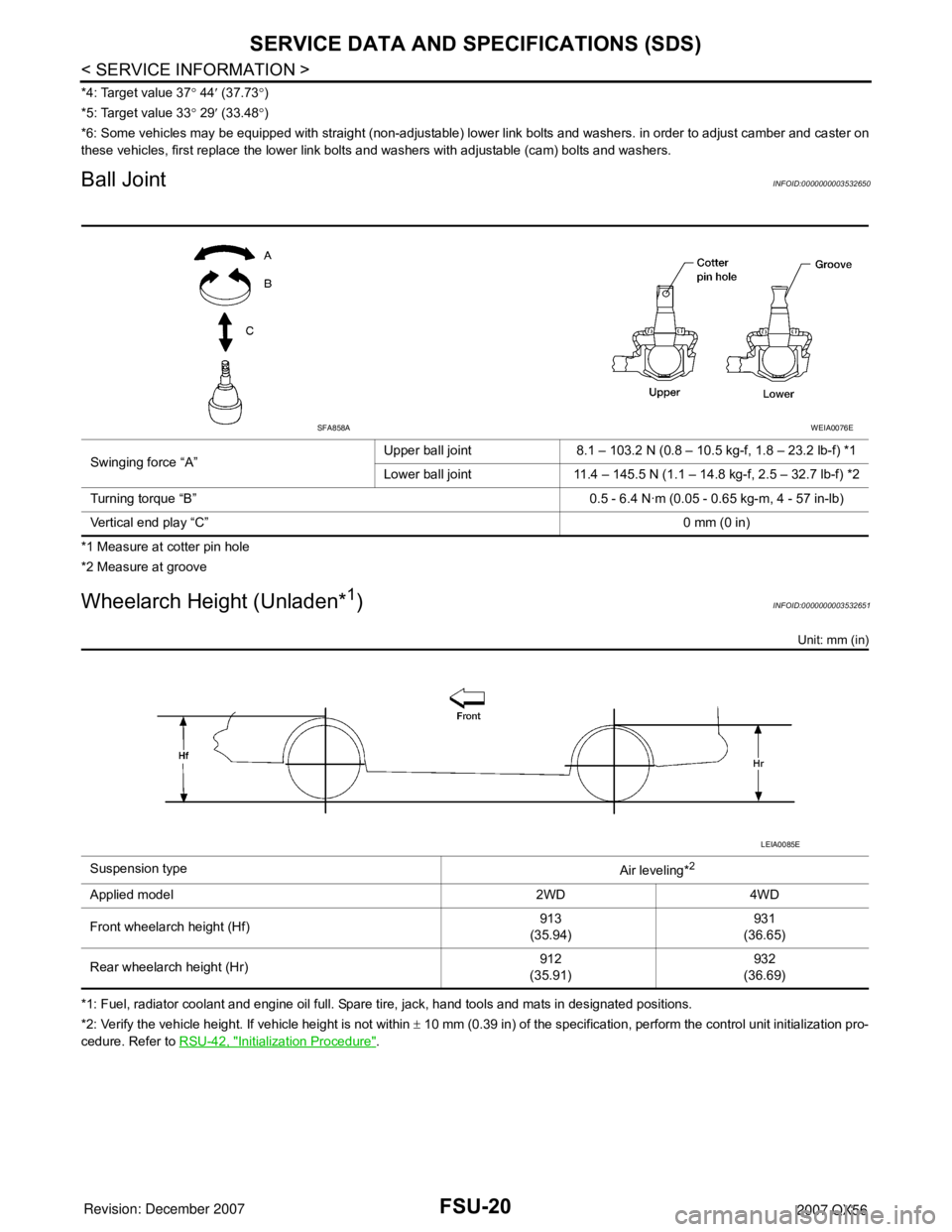
*4: Target value 37° 44′ (37.73°)
*5: Target value 33° 29′ (33.48°)
*6: Some vehicles may be equipped with straight (non-adjustable) lower link bolts and washers. in order to adjust camber and caster on
these vehicles, first replace the lower link bolts and washers with adjustable (cam) bolts and washers.
Ball JointINFOID:0000000003532650
*1 Measure at cotter pin hole
*2 Measure at groove
Wheelarch Height (Unladen*1)INFOID:0000000003532651
Unit: mm (in)
*1: Fuel, radiator coolant and engine oil full. Spare tire, jack, hand tools and mats in designated positions.
*2: Verify the vehicle height. If vehicle height is not within ± 10 mm (0.39 in) of the specification, perform the control unit initialization pro-
cedure. Refer to RSU-42, "
Initialization Procedure". Swinging force “A”Upper ball joint 8.1 – 103.2 N (0.8 – 10.5 kg-f, 1.8 – 23.2 lb-f) *1
Lower ball joint 11.4 – 145.5 N (1.1 – 14.8 kg-f, 2.5 – 32.7 lb-f) *2
Turning torque “B” 0.5 - 6.4 N·m (0.05 - 0.65 kg-m, 4 - 57 in-lb)
Vertical end play “C”0 mm (0 in)
SFA858AWEIA0076E
Suspension type
Air leveling*2
Applied model 2WD 4WD
Front wheelarch height (Hf)913
(35.94)931
(36.65)
Rear wheelarch height (Hr)912
(35.91)932
(36.69)
LEIA0085E
Page 1967 of 3061
GI-1
GENERAL INFORMATION
C
D
E
F
G
H
I
J
K
L
MB
GI
SECTION GI
N
O
P
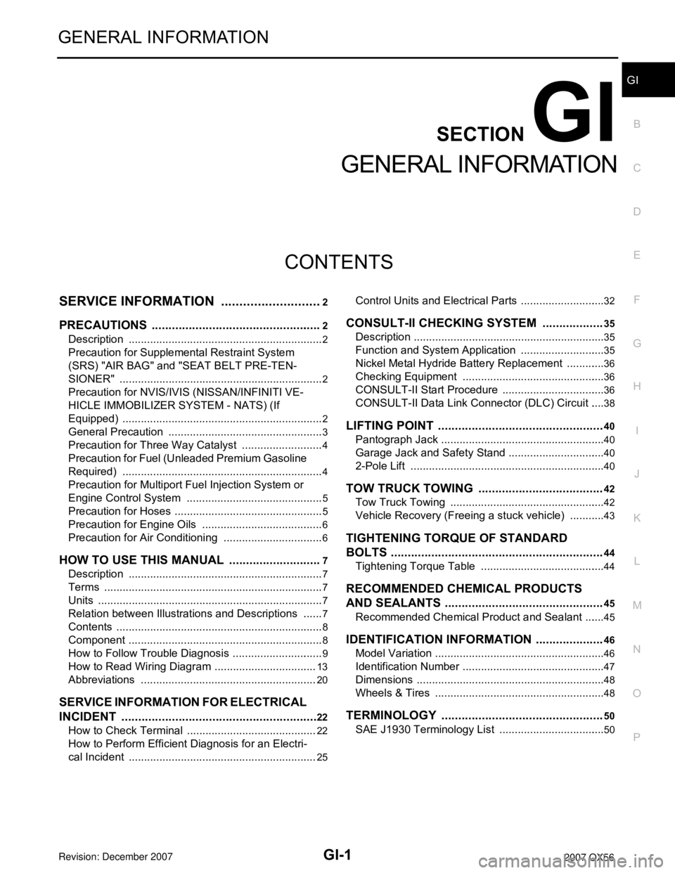
CONTENTS
GENERAL INFORMATION
SERVICE INFORMATION ............................2
PRECAUTIONS ...................................................2
Description ................................................................2
Precaution for Supplemental Restraint System
(SRS) "AIR BAG" and "SEAT BELT PRE-TEN-
SIONER" ...................................................................
2
Precaution for NVIS/IVIS (NISSAN/INFINITI VE-
HICLE IMMOBILIZER SYSTEM - NATS) (If
Equipped) ..................................................................
2
General Precaution ...................................................3
Precaution for Three Way Catalyst ...........................4
Precaution for Fuel (Unleaded Premium Gasoline
Required) ..................................................................
4
Precaution for Multiport Fuel Injection System or
Engine Control System .............................................
5
Precaution for Hoses .................................................5
Precaution for Engine Oils ........................................6
Precaution for Air Conditioning .................................6
HOW TO USE THIS MANUAL ............................7
Description ................................................................7
Terms ........................................................................7
Units ..........................................................................7
Relation between Illustrations and Descriptions .......7
Contents ....................................................................8
Component ................................................................8
How to Follow Trouble Diagnosis ..............................9
How to Read Wiring Diagram ..................................13
Abbreviations ..........................................................20
SERVICE INFORMATION FOR ELECTRICAL
INCIDENT ...........................................................
22
How to Check Terminal ...........................................22
How to Perform Efficient Diagnosis for an Electri-
cal Incident ..............................................................
25
Control Units and Electrical Parts ............................32
CONSULT-II CHECKING SYSTEM ..................35
Description ...............................................................35
Function and System Application ............................35
Nickel Metal Hydride Battery Replacement .............36
Checking Equipment ...............................................36
CONSULT-II Start Procedure ..................................36
CONSULT-II Data Link Connector (DLC) Circuit .....38
LIFTING POINT .................................................40
Pantograph Jack ......................................................40
Garage Jack and Safety Stand ................................40
2-Pole Lift ................................................................40
TOW TRUCK TOWING .....................................42
Tow Truck Towing ...................................................42
Vehicle Recovery (Freeing a stuck vehicle) ............43
TIGHTENING TORQUE OF STANDARD
BOLTS ...............................................................
44
Tightening Torque Table .........................................44
RECOMMENDED CHEMICAL PRODUCTS
AND SEALANTS ...............................................
45
Recommended Chemical Product and Sealant .......45
IDENTIFICATION INFORMATION ....................46
Model Variation ........................................................46
Identification Number ...............................................47
Dimensions ..............................................................48
Wheels & Tires ........................................................48
TERMINOLOGY ................................................50
SAE J1930 Terminology List ...................................50