2007 INFINITI QX56 engine oil
[x] Cancel search: engine oilPage 2619 of 3061
REAR SUSPENSION MEMBER
RSU-29
< SERVICE INFORMATION >
C
D
F
G
H
I
J
K
L
MA
B
RSU
N
O
P
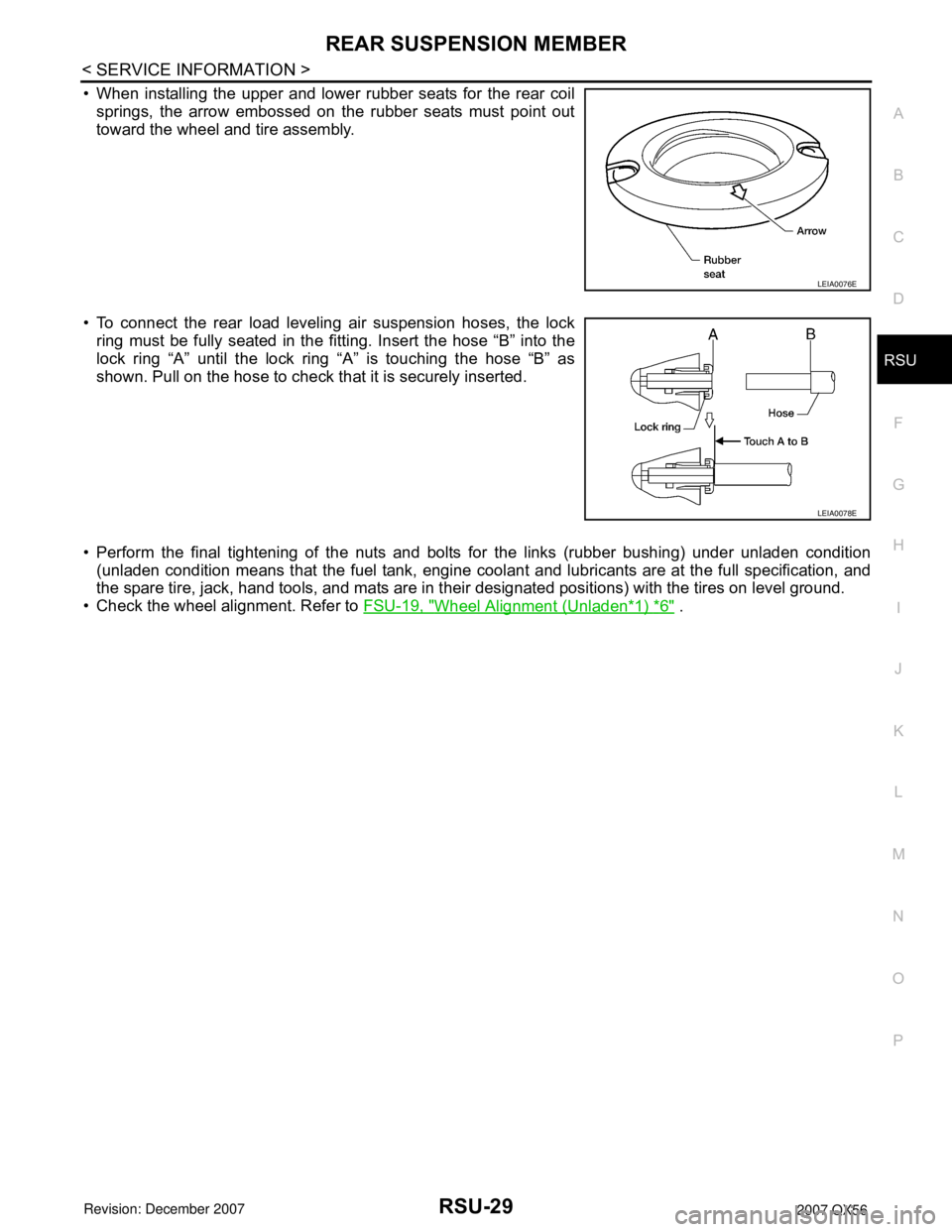
• When installing the upper and lower rubber seats for the rear coil
springs, the arrow embossed on the rubber seats must point out
toward the wheel and tire assembly.
• To connect the rear load leveling air suspension hoses, the lock
ring must be fully seated in the fitting. Insert the hose “B” into the
lock ring “A” until the lock ring “A” is touching the hose “B” as
shown. Pull on the hose to check that it is securely inserted.
• Perform the final tightening of the nuts and bolts for the links (rubber bushing) under unladen condition
(unladen condition means that the fuel tank, engine coolant and lubricants are at the full specification, and
the spare tire, jack, hand tools, and mats are in their designated positions) with the tires on level ground.
• Check the wheel alignment. Refer to FSU-19, "
Wheel Alignment (Unladen*1) *6" .
LEIA0076E
LEIA0078E
Page 2634 of 3061
RSU-44
< SERVICE INFORMATION >
SERVICE DATA AND SPECIFICATIONS (SDS)
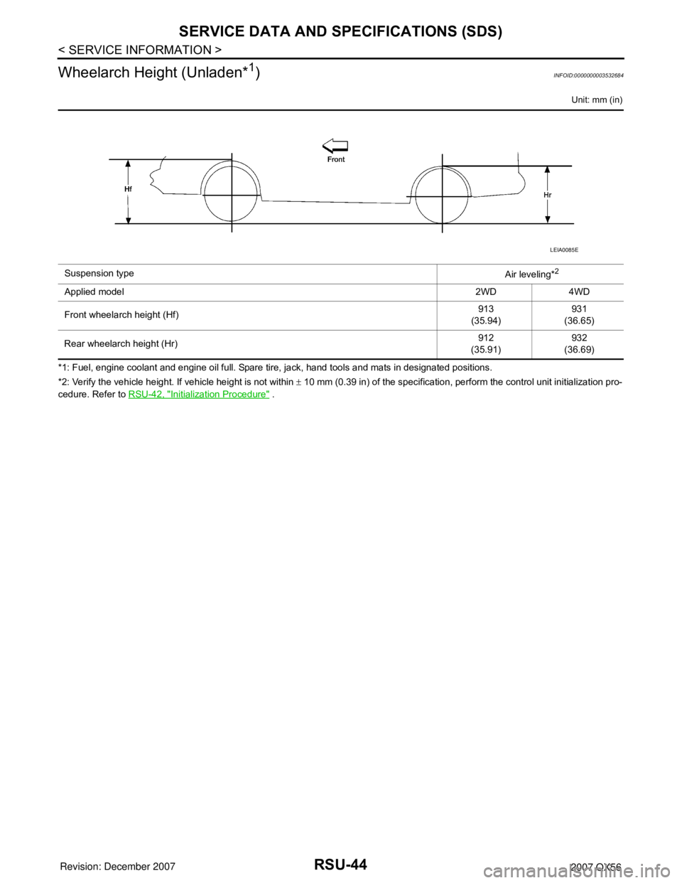
Wheelarch Height (Unladen*
1)INFOID:0000000003532684
Unit: mm (in)
*1: Fuel, engine coolant and engine oil full. Spare tire, jack, hand tools and mats in designated positions.
*2: Verify the vehicle height. If vehicle height is not within ± 10 mm (0.39 in) of the specification, perform the control unit initialization pro-
cedure. Refer to RSU-42, "
Initialization Procedure" . Suspension type
Air leveling*
2
Applied model2WD 4WD
Front wheelarch height (Hf)913
(35.94)931
(36.65)
Rear wheelarch height (Hr)912
(35.91)932
(36.69)
LEIA0085E
Page 2840 of 3061

TF-18
< SERVICE INFORMATION >
ALL-MODE 4WD SYSTEM
LINE PRESSURE SWITCH
• With the transfer system design, control of the oil pressure provides the transmission of drive torque to the
front wheels. The main pressure to control the oil pressure is referred to as the line pressure.
• The line pressure switch determines whether or not adequate line pressure has built up under different oper-
ating conditions.
• The line pressure switch turns ON when line pressure is produced.
• The line pressure switch senses line pressure abnormalities and turns the 4WD warning lamp ON.
CLUTCH PRESSURE SWITCH
• The clutch pressure switch determines whether or not adequate clutch pressure has built up under different
operating conditions.
• The clutch pressure switch turns ON when clutch pressure is produced.
• The clutch pressure switch senses clutch pressure abnormalities and turns the 4WD warning lamp ON.
TRANSFER FLUID TEMPERATURE SENSOR
The transfer temperature sensor detects the transfer fluid temperature and sends a signal to the transfer con-
trol unit.
TRANSFER CONTROL UNIT
• Transfer control unit controls transfer control device by input signals of each sensor and each switch.
• Self-diagnosis can be done.
TRANSFER CONTROL DEVICE
The transfer control device changes the state of transfer assembly between 2WD, AUTO, 4H⇔4LO with the
2WD, AUTO, 4H and 4LO signals of 4WD shift switch.
NOTE:
• To shift between 4H⇔4LO, stop the vehicle, depress the brake pedal and shift the transmission selector to
the "N" position. Depress and turn the 4WD shift switch. The shift switch will not shift to the desired mode if
the transmission is not in "N" or the vehicle is moving. The 4LO indicator lamp will be lit when the 4LO is
engaged.
• Actuator motor and actuator position switch are integrated.
4WD SHIFT SWITCH AND INDICATOR LAMP
4WD Shift Switch
The 4WD shift switch allows selection from 2WD, AUTO, 4H or 4LO.
4WD Shift Indicator Lamp
• Displays driving conditions selected by 4WD shift switch with 2WD, AUTO and 4H indicators while engine is
running. (When 4WD warning lamp is turned on, all 4WD shift indicator lamps are turned off.)
• Turns ON for approximately 1 second when ignition switch is turned ON, for purpose of lamp check.
4LO Indicator Lamp
• Displays 4LO condition while engine is running. 4LO indicator lamp flashes if transfer gear does not shift
completely under 2WD, AUTO, 4H⇔4LO. (When 4WD warning lamp is turned on, 4LO indicator lamp is
turned off.)
• Turns ON for approximately 1 second when ignition switch is turned ON, for purpose of lamp check.
4WD WARNING LAMP
Turns ON or FLASH when there is a malfunction in 4WD system.
Also turns ON when ignition switch is turned ON, for purpose of lamp check. Turns OFF for approximately 1
second after the engine starts if system is normal.
4WD Warning Lamp Indication
Condition Content 4WD warning lamp
During self-diagnosis Indicates the malfunction position by number of flickers. Flickers at malfunction mode.
Lamp check*Checks the lamp by turning ON during engine starting. After
engine starts, it turns OFF if there are no malfunctions.ON
Malfunction in 4WD system*Turns ON to indicate malfunction. When ignition switch is
turned to “OFF” or the malfunction is corrected, it turns OFF.ON
When vehicle is driven with different
diameters of front and rear tiresFlickers once every 2 seconds.
Turns OFF when ignition switch is “OFF”.Flickers once every 2 sec-
onds.
Page 2866 of 3061
![INFINITI QX56 2007 Factory Service Manual TF-44
< SERVICE INFORMATION >
TROUBLE DIAGNOSIS
CAUTION:
• If “CAN COMM CIRCUIT [U1000]” is displayed with other DTCs, first perform the trouble diagnosis for CAN communication
line.
• If “V INFINITI QX56 2007 Factory Service Manual TF-44
< SERVICE INFORMATION >
TROUBLE DIAGNOSIS
CAUTION:
• If “CAN COMM CIRCUIT [U1000]” is displayed with other DTCs, first perform the trouble diagnosis for CAN communication
line.
• If “V](/manual-img/42/57029/w960_57029-2865.png)
TF-44
< SERVICE INFORMATION >
TROUBLE DIAGNOSIS
CAUTION:
• If “CAN COMM CIRCUIT [U1000]” is displayed with other DTCs, first perform the trouble diagnosis for CAN communication
line.
• If “VHCL SPEED SEN·AT [P1808]”, “ABS OP SIG [P1830]”, “VDC OP SIG [P1831]” or “TCS OP SIG [P1832]” is displayed, first
perform the trouble diagnosis for ABS system.
• If “VHCL SPEED SEN·AT [P1808]”, is displayed, first perform the trouble diagnosis for A/T system.
NOTE:
• If "SHIFT ACT POSI SW [P1818]" or “SHIFT ACT CIR [P1819]” is displayed, first erase self-diagnostic results. ("SHIFT ACT POSI SW
[P1818]" or “SHIFT ACT CIR [P1819]” may be displayed after installing transfer control unit or transfer assembly.)
• If “CL PRES SW [P1827]” or “LINE PRES SW [P1828]” is displayed only while driving in reverse, check the continuity of “R” position
on A/T PNP switch. When there is nothing wrong with the electrical system, check the hydraulic system.
How to Erase Self-diagnostic Results
1. Perform applicable inspection of malfunctioning item and then repair or replace.
SHIFT ACT CIR
[P1819]• Transfer control device actuator circuit is shorted or open. (Mal-
functions are detected when transfer shift relay circuit is open/
shorted or relay monitor circuit is open/shorted.)
• Malfunction occurs in transfer control device drive circuit.
• Malfunction is detected in transfer shut off relay.TF-72, "Transfer Control Device"
Malfunction is detected in transfer shut off relay.TF-51, "Power Supply Circuit for
Transfer Control Unit"
ENGINE SPEED SIG
[P1820]• Malfunction is detected in engine speed signal that is output from
ECM through CAN communication.
• Improper signal is input while driving.TF-76, "Engine Speed Signal
(ECM)"
DUTY SOLENOID
[P1822]• Proper voltage is not applied to clutch pressure solenoid valve
due to open or short circuit.TF-76, "Clutch Pressure Sole-
noid"
2-4WD SOLENOID
[P1823]• Proper voltage is not applied to 2-4WD solenoid valve due to open
or short circuit.TF-80, "2-4WD Solenoid"
MOTOR RELAY
[P1824]• Motor does not operate properly due to open or short circuit in
transfer motor or motor relay.TF-84, "Transfer Motor"
OIL TEMP SEN
[P1826]• Signal voltage from fluid temperature sensor is abnormally high
(Transfer fluid temperature is abnormally low) while driving.TF-90, "Transfer Fluid Tempera-
ture"
CLUTCH PRES SW
[P1827]• Improper signal from clutch pressure switch is input due to open or
short circuit.
• Malfunction occurs in clutch pressure switch or hydraulic circuit.TF-92, "Clutch Pressure Switch"
LINE PRES SW
[P1828]• Improper signal from line pressure switch is input due to open or
short circuit.
• Malfunction occurs in line pressure switch or hydraulic circuit.TF-94, "Line Pressure Switch"
THROTTLE POSI SEN
[P1829]• Malfunction is detected in accelerator pedal position signal that is
output from ECM through CAN communication.
• Signal voltage from accelerator pedal position sensor is abnormal-
ly high or low.TF-97, "Throttle Position Signal
(ECM)"
ABS OP SIG
[P1830]• Malfunction is detected in ABS operation signal that is output from
ABS actuator and electric unit (control unit) through CAN commu-
nication.TF-97, "ABS Operation Signal
(ABS)"
VDC OP SIG
[P1831]• Malfunction is detected in VDC operation signal that is output from
ABS actuator and electric unit (control unit) through CAN commu-
nication.TF-98, "VDC Operation Signal
(ABS)"
TCS OP SIG
[P1832]• Malfunction is detected in TCS operation signal that is output from
ABS through CAN communication.TF-98, "TCS Operation Signal
(ABS)"
CAN COMM CIRCUIT
[U1000]• Malfunction has been detected from CAN communication line.TF-99, "CAN Communication
Line"
NO DTC IS DETECTED.
FURTHER TESTING MAY
BE REQUIRED.• No NG item has been detected. — Items (CONSULT-II screen
terms)Diagnostic item is detected when... Check item
Page 2947 of 3061
TRANSFER MOTOR
TF-125
< SERVICE INFORMATION >
C
E
F
G
H
I
J
K
L
MA
B
TF
N
O
P
TRANSFER MOTOR
Removal and InstallationINFOID:0000000003532568
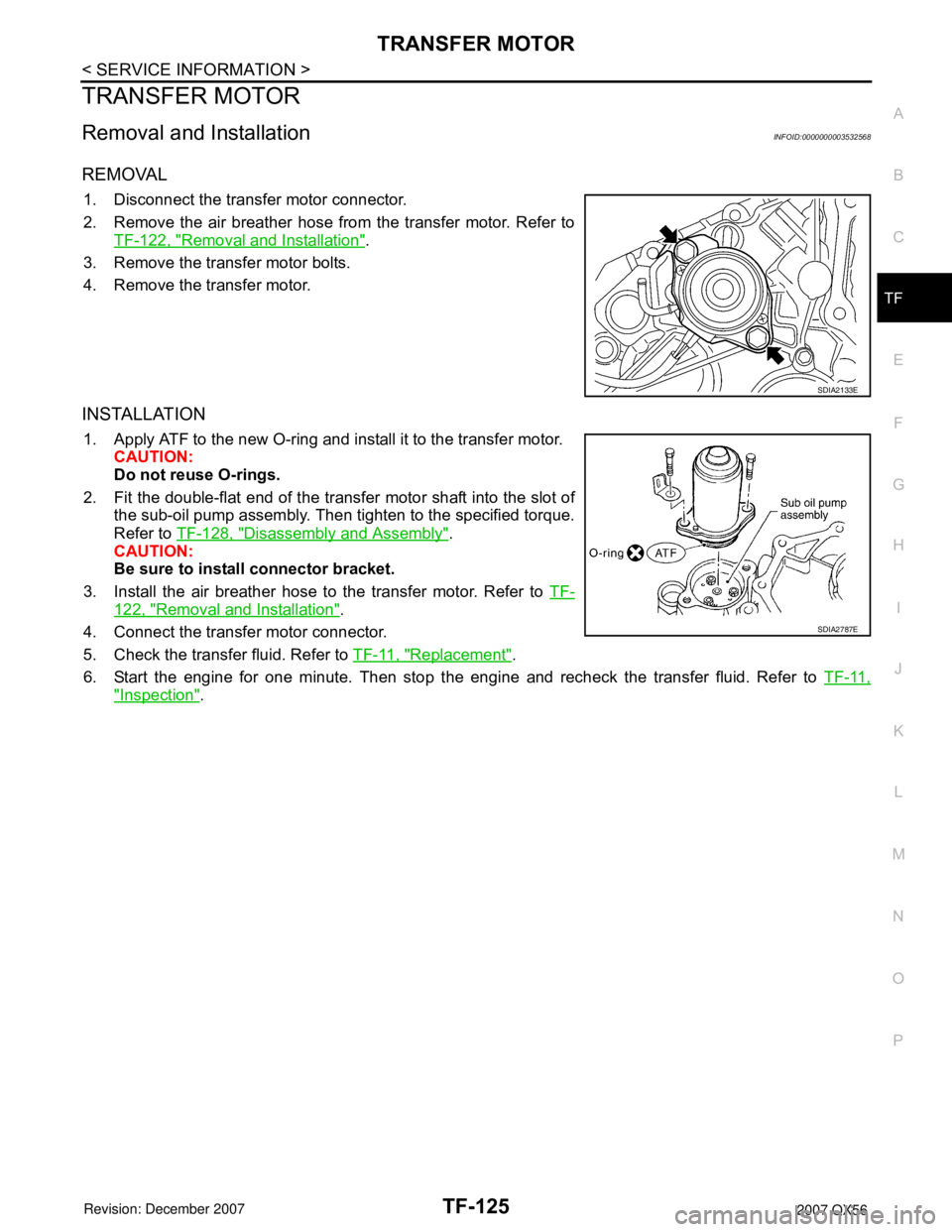
REMOVAL
1. Disconnect the transfer motor connector.
2. Remove the air breather hose from the transfer motor. Refer to
TF-122, "
Removal and Installation".
3. Remove the transfer motor bolts.
4. Remove the transfer motor.
INSTALLATION
1. Apply ATF to the new O-ring and install it to the transfer motor.
CAUTION:
Do not reuse O-rings.
2. Fit the double-flat end of the transfer motor shaft into the slot of
the sub-oil pump assembly. Then tighten to the specified torque.
Refer to TF-128, "
Disassembly and Assembly".
CAUTION:
Be sure to install connector bracket.
3. Install the air breather hose to the transfer motor. Refer to TF-
122, "Removal and Installation".
4. Connect the transfer motor connector.
5. Check the transfer fluid. Refer to TF-11, "
Replacement".
6. Start the engine for one minute. Then stop the engine and recheck the transfer fluid. Refer to TF-11,
"Inspection".
SDIA2133E
SDIA2787E
Page 2949 of 3061
TRANSFER OIL FILTER
TF-127
< SERVICE INFORMATION >
C
E
F
G
H
I
J
K
L
MA
B
TF
N
O
P
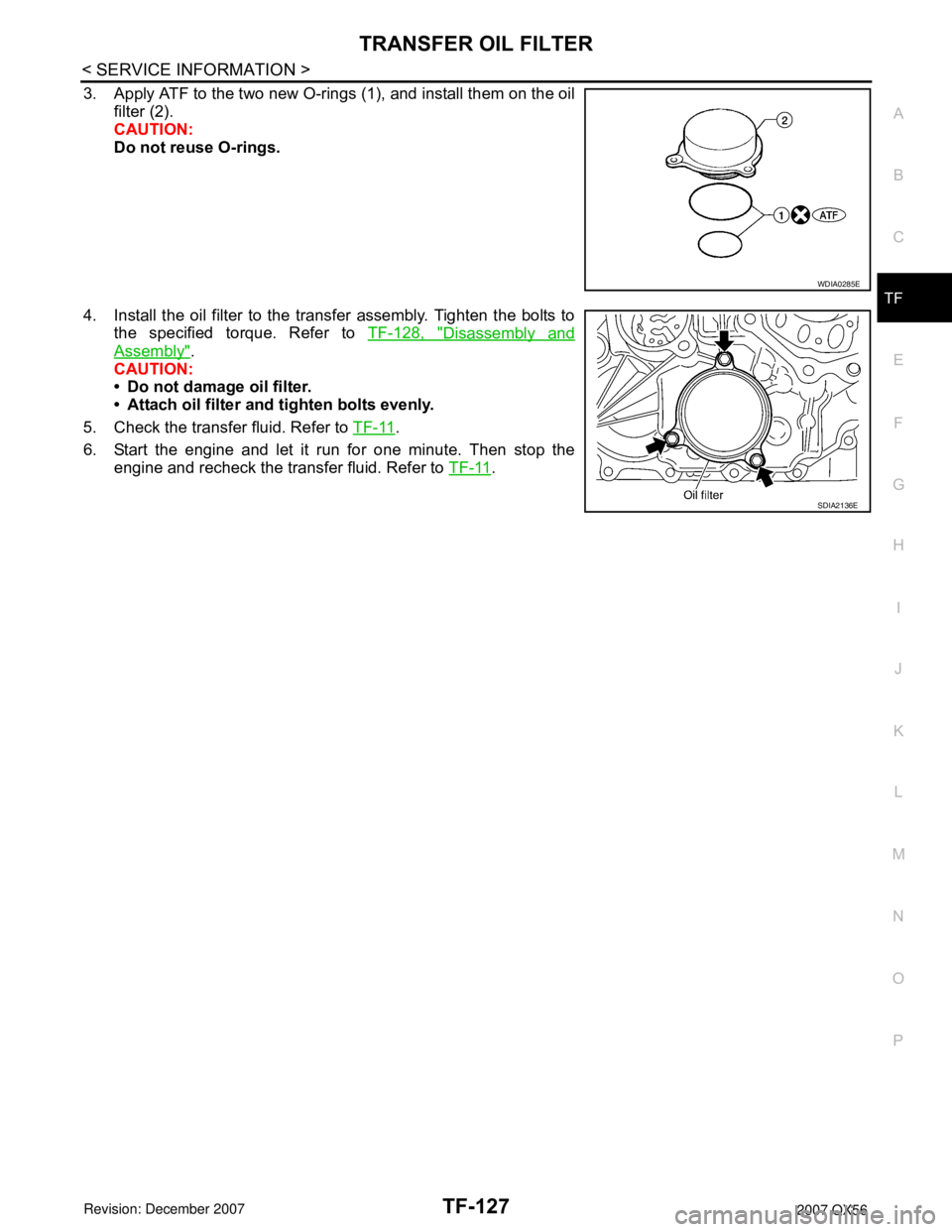
3. Apply ATF to the two new O-rings (1), and install them on the oil
filter (2).
CAUTION:
Do not reuse O-rings.
4. Install the oil filter to the transfer assembly. Tighten the bolts to
the specified torque. Refer to TF-128, "
Disassembly and
Assembly".
CAUTION:
• Do not damage oil filter.
• Attach oil filter and tighten bolts evenly.
5. Check the transfer fluid. Refer to TF-11
.
6. Start the engine and let it run for one minute. Then stop the
engine and recheck the transfer fluid. Refer to TF-11
.
WDIA0285E
SDIA2136E
Page 2950 of 3061
TF-128
< SERVICE INFORMATION >
TRANSFER ASSEMBLY
TRANSFER ASSEMBLY
Removal and InstallationINFOID:0000000003532570
REMOVAL
1. Remove the drain plug and gasket. Drain the fluid. Refer to TF-11, "Replacement".
2. Remove the A/T undercover using power tool.
3. Remove the center exhaust tube and main muffler. Refer to EX-3, "
Removal and Installation".
4. Remove the front and rear propeller shafts. Refer to PR-4, "
Removal and Installation" (front), PR-8,
"Removal and Installation" (rear).
CAUTION:
Do not damage spline, sleeve yoke and rear oil seal when removing rear propeller shaft.
NOTE:
Insert a plug into the rear oil seal after removing the rear propeller shaft.
5. Remove the A/T nuts from the A/T crossmember.
6. Position two suitable jacks under the A/T and transfer assembly.
7. Remove the crossmember. Refer to AT-223, "
Removal and Installation (2WD)".
WARNING:
Support A/T and transfer assembly using two suitable jacks while removing crossmember.
8. Disconnect the electrical connectors from the following:
•ATP switch
• Neutral 4LO switch
• Wait detection switch
• Transfer motor
• Transfer control device
• Transfer terminal cord assembly
9. Disconnect each air breather hose from the following. Refer to TF-122, "
Removal and Installation".
• Actuator
• Breather tube (transfer)
• Transfer motor (case connector)
10. Remove the transfer control device from the extension housing.
11. Remove the transfer to A/T and A/T to transfer bolts.
WARNING:
Support transfer assembly with suitable jack while removing it.
12. Remove the transfer assembly.
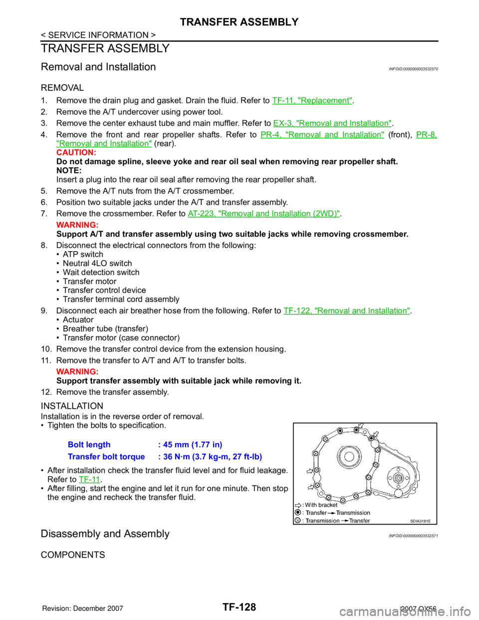
INSTALLATION
Installation is in the reverse order of removal.
• Tighten the bolts to specification.
• After installation check the transfer fluid level and for fluid leakage.
Refer to TF-11
.
• After filling, start the engine and let it run for one minute. Then stop
the engine and recheck the transfer fluid.
Disassembly and AssemblyINFOID:0000000003532571
COMPONENTS
Bolt length : 45 mm (1.77 in)
Transfer bolt torque : 36 N·m (3.7 kg-m, 27 ft-lb)
SDIA3181E