2007 INFINITI QX56 relay
[x] Cancel search: relayPage 2075 of 3061
GW-56
< SERVICE INFORMATION >
POWER WINDOW SYSTEM
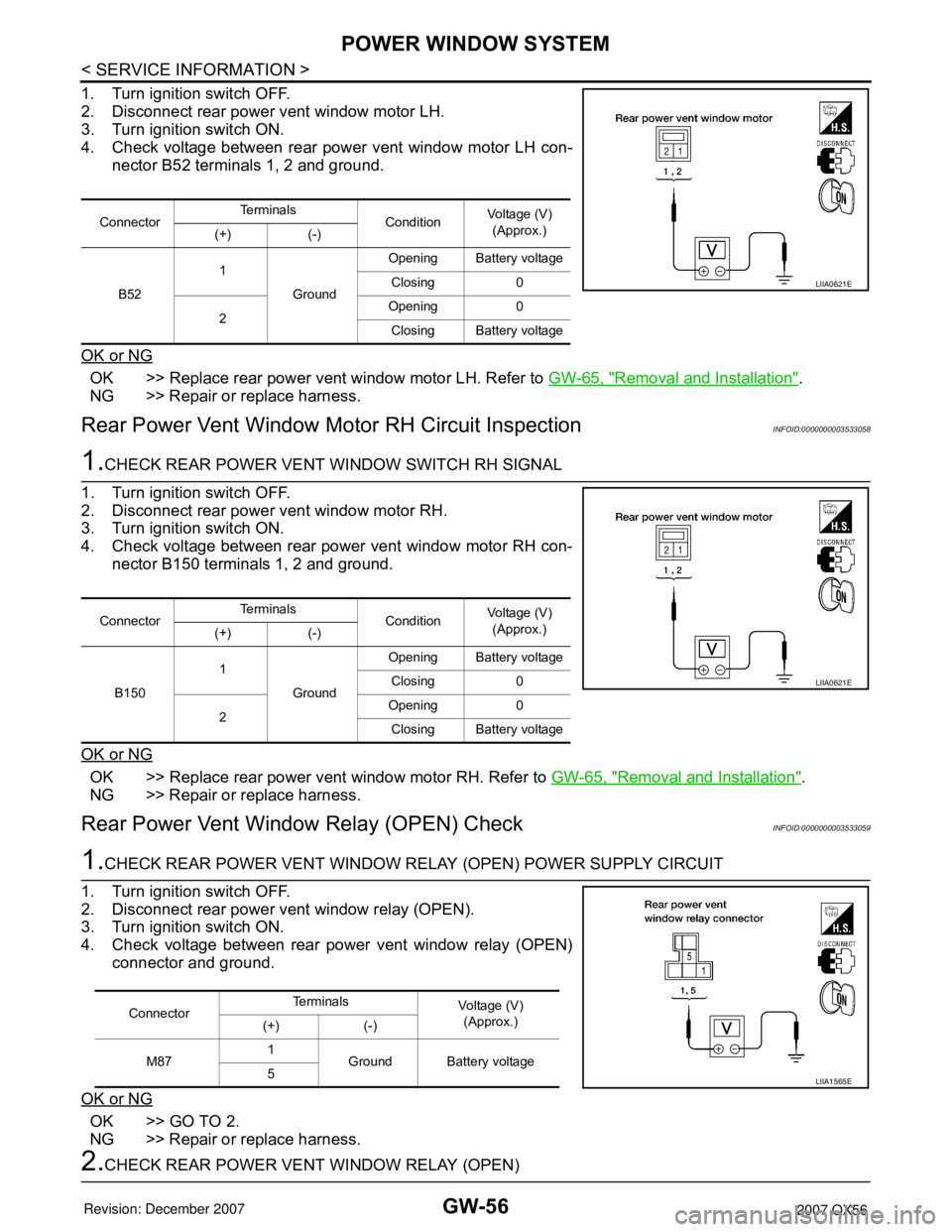
1. Turn ignition switch OFF.
2. Disconnect rear power vent window motor LH.
3. Turn ignition switch ON.
4. Check voltage between rear power vent window motor LH con-
nector B52 terminals 1, 2 and ground.
OK or NG
OK >> Replace rear power vent window motor LH. Refer to GW-65, "Removal and Installation".
NG >> Repair or replace harness.
Rear Power Vent Window Motor RH Circuit InspectionINFOID:0000000003533058
1.CHECK REAR POWER VENT WINDOW SWITCH RH SIGNAL
1. Turn ignition switch OFF.
2. Disconnect rear power vent window motor RH.
3. Turn ignition switch ON.
4. Check voltage between rear power vent window motor RH con-
nector B150 terminals 1, 2 and ground.
OK or NG
OK >> Replace rear power vent window motor RH. Refer to GW-65, "Removal and Installation".
NG >> Repair or replace harness.
Rear Power Vent Window Relay (OPEN) CheckINFOID:0000000003533059
1.CHECK REAR POWER VENT WINDOW RELAY (OPEN) POWER SUPPLY CIRCUIT
1. Turn ignition switch OFF.
2. Disconnect rear power vent window relay (OPEN).
3. Turn ignition switch ON.
4. Check voltage between rear power vent window relay (OPEN)
connector and ground.
OK or NG
OK >> GO TO 2.
NG >> Repair or replace harness.
2.CHECK REAR POWER VENT WINDOW RELAY (OPEN)
ConnectorTe r m i n a l s
ConditionVoltage (V)
(Approx.)
(+) (-)
B521
GroundOpening Battery voltage
Closing 0
2Opening 0
Closing Battery voltage
LIIA0621E
ConnectorTe r m i n a l s
ConditionVoltage (V)
(Approx.)
(+) (-)
B1501
GroundOpening Battery voltage
Closing 0
2Opening 0
Closing Battery voltage
LIIA0621E
ConnectorTe r m i n a l s
Voltage (V)
(Approx.)
(+) (-)
M871
Ground Battery voltage
5
LIIA1565E
Page 2076 of 3061
POWER WINDOW SYSTEM
GW-57
< SERVICE INFORMATION >
C
D
E
F
G
H
J
K
L
MA
B
GW
N
O
P
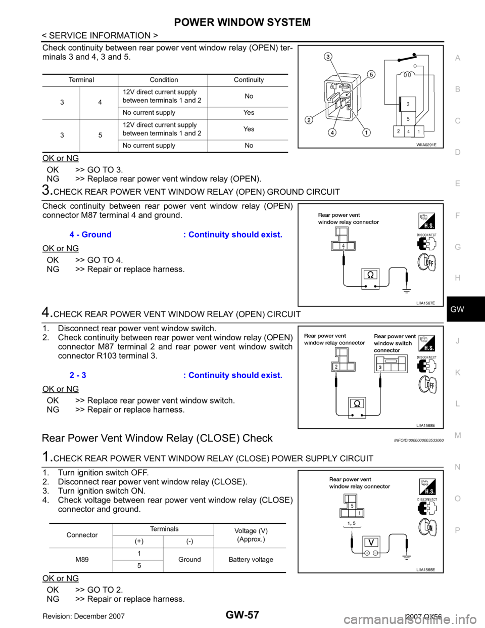
Check continuity between rear power vent window relay (OPEN) ter-
minals 3 and 4, 3 and 5.
OK or NG
OK >> GO TO 3.
NG >> Replace rear power vent window relay (OPEN).
3.CHECK REAR POWER VENT WINDOW RELAY (OPEN) GROUND CIRCUIT
Check continuity between rear power vent window relay (OPEN)
connector M87 terminal 4 and ground.
OK or NG
OK >> GO TO 4.
NG >> Repair or replace harness.
4.CHECK REAR POWER VENT WINDOW RELAY (OPEN) CIRCUIT
1. Disconnect rear power vent window switch.
2. Check continuity between rear power vent window relay (OPEN)
connector M87 terminal 2 and rear power vent window switch
connector R103 terminal 3.
OK or NG
OK >> Replace rear power vent window switch.
NG >> Repair or replace harness.
Rear Power Vent Window Relay (CLOSE) CheckINFOID:0000000003533060
1.CHECK REAR POWER VENT WINDOW RELAY (CLOSE) POWER SUPPLY CIRCUIT
1. Turn ignition switch OFF.
2. Disconnect rear power vent window relay (CLOSE).
3. Turn ignition switch ON.
4. Check voltage between rear power vent window relay (CLOSE)
connector and ground.
OK or NG
OK >> GO TO 2.
NG >> Repair or replace harness.
Terminal Condition Continuity
3412V direct current supply
between terminals 1 and 2No
No current supply Yes
3512V direct current supply
between terminals 1 and 2Ye s
No current supply No
WIIA0291E
4 - Ground : Continuity should exist.
LIIA1567E
2 - 3 : Continuity should exist.
LIIA1568E
ConnectorTe r m i n a l s
Voltage (V)
(Approx.)
(+) (-)
M891
Ground Battery voltage
5
LIIA1565E
Page 2077 of 3061
GW-58
< SERVICE INFORMATION >
POWER WINDOW SYSTEM
2.CHECK REAR POWER VENT WINDOW RELAY (CLOSE)
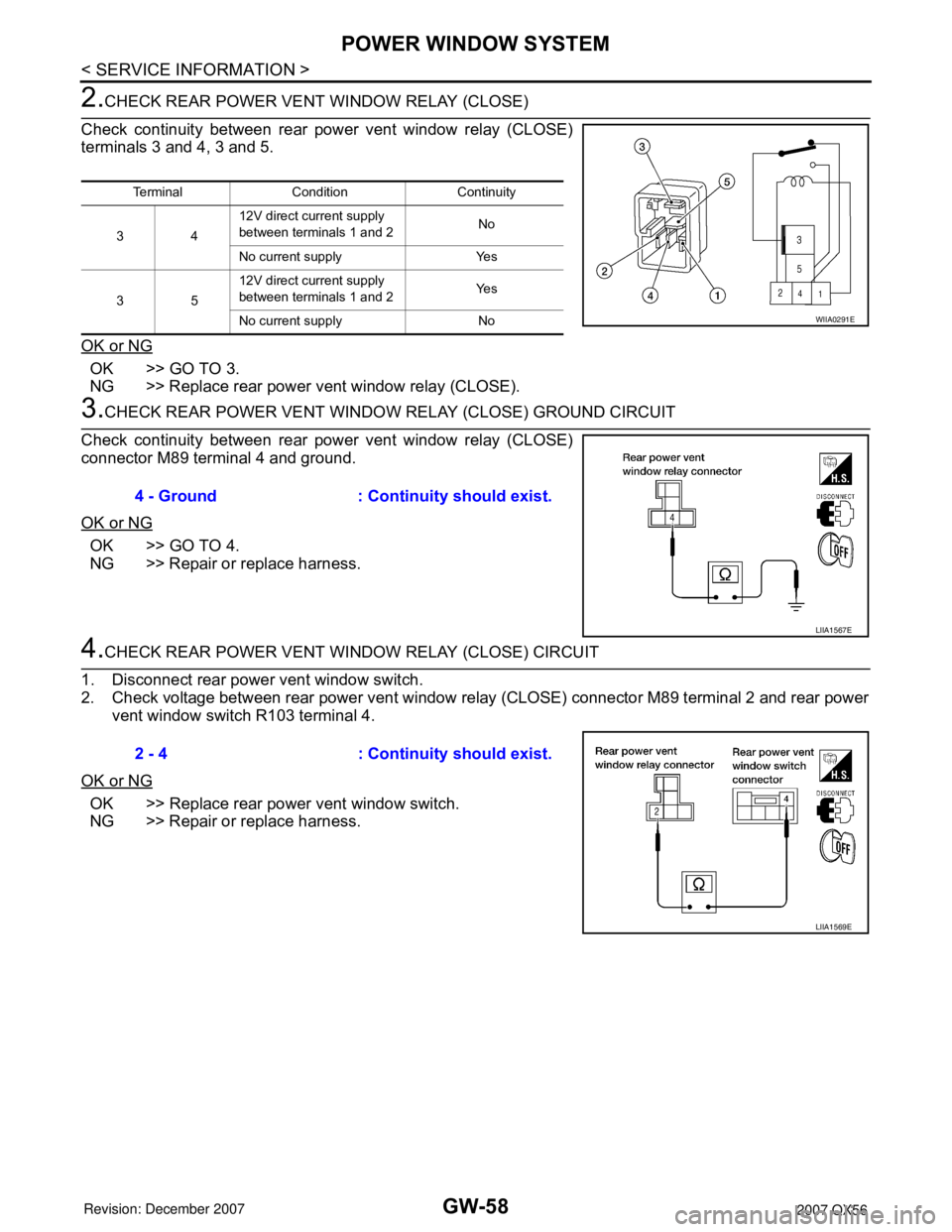
Check continuity between rear power vent window relay (CLOSE)
terminals 3 and 4, 3 and 5.
OK or NG
OK >> GO TO 3.
NG >> Replace rear power vent window relay (CLOSE).
3.CHECK REAR POWER VENT WINDOW RELAY (CLOSE) GROUND CIRCUIT
Check continuity between rear power vent window relay (CLOSE)
connector M89 terminal 4 and ground.
OK or NG
OK >> GO TO 4.
NG >> Repair or replace harness.
4.CHECK REAR POWER VENT WINDOW RELAY (CLOSE) CIRCUIT
1. Disconnect rear power vent window switch.
2. Check voltage between rear power vent window relay (CLOSE) connector M89 terminal 2 and rear power
vent window switch R103 terminal 4.
OK or NG
OK >> Replace rear power vent window switch.
NG >> Repair or replace harness.
Terminal Condition Continuity
3412V direct current supply
between terminals 1 and 2No
No current supply Yes
3512V direct current supply
between terminals 1 and 2Ye s
No current supply No
WIIA0291E
4 - Ground : Continuity should exist.
LIIA1567E
2 - 4 : Continuity should exist.
LIIA1569E
Page 2087 of 3061
GW-68
< SERVICE INFORMATION >
REAR WINDOW DEFOGGER
REAR WINDOW DEFOGGER
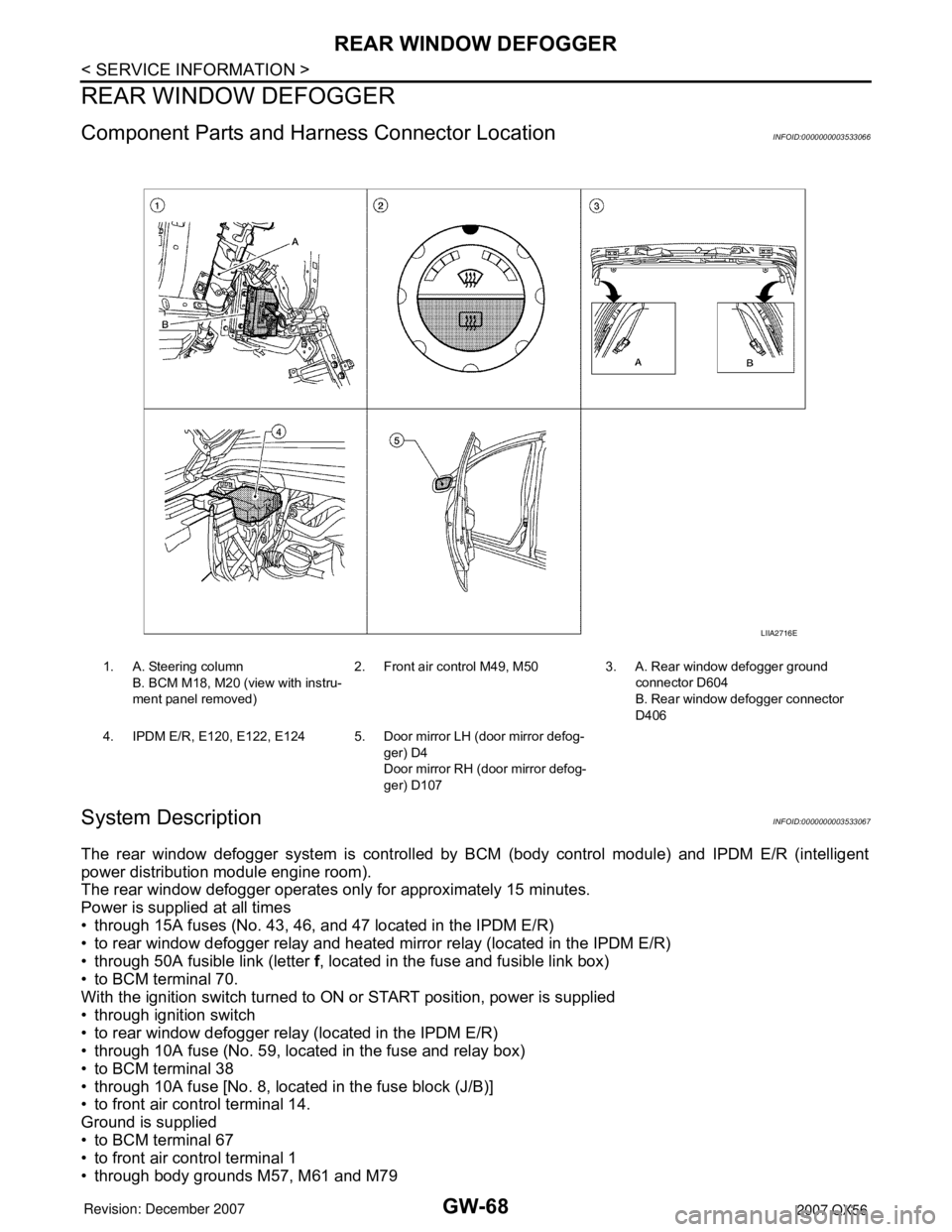
Component Parts and Harness Connector LocationINFOID:0000000003533066
System DescriptionINFOID:0000000003533067
The rear window defogger system is controlled by BCM (body control module) and IPDM E/R (intelligent
power distribution module engine room).
The rear window defogger operates only for approximately 15 minutes.
Power is supplied at all times
• through 15A fuses (No. 43, 46, and 47 located in the IPDM E/R)
• to rear window defogger relay and heated mirror relay (located in the IPDM E/R)
• through 50A fusible link (letter f, located in the fuse and fusible link box)
• to BCM terminal 70.
With the ignition switch turned to ON or START position, power is supplied
• through ignition switch
• to rear window defogger relay (located in the IPDM E/R)
• through 10A fuse (No. 59, located in the fuse and relay box)
• to BCM terminal 38
• through 10A fuse [No. 8, located in the fuse block (J/B)]
• to front air control terminal 14.
Ground is supplied
• to BCM terminal 67
• to front air control terminal 1
• through body grounds M57, M61 and M79
1. A. Steering column
B. BCM M18, M20 (view with instru-
ment panel removed)2. Front air control M49, M50 3. A. Rear window defogger ground
connector D604
B. Rear window defogger connector
D406
4. IPDM E/R, E120, E122, E124 5. Door mirror LH (door mirror defog-
ger) D4
Door mirror RH (door mirror defog-
ger) D107
LIIA2716E
Page 2088 of 3061

REAR WINDOW DEFOGGER
GW-69
< SERVICE INFORMATION >
C
D
E
F
G
H
J
K
L
MA
B
GW
N
O
P
• to IPDM E/R terminals 38 and 59
• through body grounds E9, E15 and E24.
When front air control (rear window defogger switch) is turned to ON, ground is supplied
• to BCM terminal 9
• through front air control terminal 11
• through front air control terminal 1
• through body grounds M57, M61 and M79.
Then rear window defogger switch is illuminated.
Then BCM recognizes that rear window defogger switch is turned to ON.
Then it sends rear window defogger switch signals to IPDM E/R and display control unit via CAN communica-
tion (CAN-H, CAN-L).
When display control unit receives rear window defogger switch signals, and displays on the screen.
When IPDM E/R receives rear window defogger switch signals, ground is supplied
• to rear window defogger relay (located in the IPDM E/R)
• through IPDM E/R terminal 38
• through IPDM E/R terminal 59
• through body grounds E9, E15 and E24
and then rear window defogger relay is energized.
With power and ground supplied, rear window defogger filaments heat and defog the rear window.
When rear window defogger relay is turned to ON, power is supplied
• through heated mirror relay (located in the IPDM E/R)
• through IPDM E/R terminal 23
• to door mirror defogger (LH and RH) terminal 10.
Door mirror defogger (LH and RH) is grounded through body grounds M57, M61 and M79.
With power and ground supplied, rear window defogger filaments heat and defog the rear window and door
mirror defogger filaments heat and defog the mirror.
CAN Communication System DescriptionINFOID:0000000003533068
Refer to LAN-4.
Page 2096 of 3061
REAR WINDOW DEFOGGER
GW-77
< SERVICE INFORMATION >
C
D
E
F
G
H
J
K
L
MA
B
GW
N
O
P
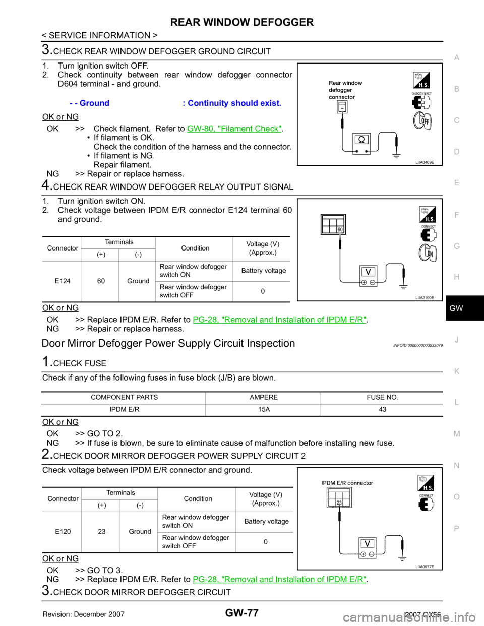
3.CHECK REAR WINDOW DEFOGGER GROUND CIRCUIT
1. Turn ignition switch OFF.
2. Check continuity between rear window defogger connector
D604 terminal - and ground.
OK or NG
OK >> Check filament. Refer to GW-80, "Filament Check".
• If filament is OK.
Check the condition of the harness and the connector.
• If filament is NG.
Repair filament.
NG >> Repair or replace harness.
4.CHECK REAR WINDOW DEFOGGER RELAY OUTPUT SIGNAL
1. Turn ignition switch ON.
2. Check voltage between IPDM E/R connector E124 terminal 60
and ground.
OK or NG
OK >> Replace IPDM E/R. Refer to PG-28, "Removal and Installation of IPDM E/R".
NG >> Repair or replace harness.
Door Mirror Defogger Power Supply Circuit InspectionINFOID:0000000003533079
1.CHECK FUSE
Check if any of the following fuses in fuse block (J/B) are blown.
OK or NG
OK >> GO TO 2.
NG >> If fuse is blown, be sure to eliminate cause of malfunction before installing new fuse.
2.CHECK DOOR MIRROR DEFOGGER POWER SUPPLY CIRCUIT 2
Check voltage between IPDM E/R connector and ground.
OK or NG
OK >> GO TO 3.
NG >> Replace IPDM E/R. Refer to PG-28, "
Removal and Installation of IPDM E/R".
3.CHECK DOOR MIRROR DEFOGGER CIRCUIT- - Ground : Continuity should exist.
LIIA0409E
ConnectorTe r m i n a l s
ConditionVoltage (V)
(Approx.)
(+) (-)
E124 60 GroundRear window defogger
switch ON Battery voltage
Rear window defogger
switch OFF0
LIIA2190E
COMPONENT PARTS AMPERE FUSE NO.
IPDM E/R 15A 43
ConnectorTe r m i n a l s
ConditionVoltage (V)
(Approx.)
(+) (-)
E120 23 GroundRear window defogger
switch ON Battery voltage
Rear window defogger
switch OFF0
LIIA0977E
Page 2108 of 3061
IDX-4
ALPHABETICAL INDEX
Duct and grilles .............................................. ATC-170
DVD - Wiring Diagram ....................................... AV-75
DVD Entertainment System ............................... AV-72
DVD Player ........................................................ AV-73
E
ECM input/output signal ..................... EC-109
, EC-133
ECM power supply ............................. EC-150, EC-475
ECM relay ........................................................ EC-150
ECM/PW - Wiring diagram ............................... EC-476
ECTS - Wiring diagram .................................... EC-220
Electric sunroof .................................................. RF-10
Electric throttle control actuator ......... EC-595, EC-606
Electrical load signal circuit .............................. EC-657
Electrical units location ...................................... PG-65
Electronic ignition (EI) system ........................... EC-27
Engine control circuit diagram ......................... EC-107
Engine control component parts location ........... EC-98
Engine control module (ECM) .......................... EC-479
Engine control system diagram ......................... EC-24
Engine coolant .................................................. CO-10
Engine coolant temperature sensor (ECTS) ... EC-218,
EC-231
Engine fail-safe system ...................................... EC-93
Engine oil ............................................................. LU-8
Engine oil filter replacement ............................. MA-17
Engine oil precautions .......................................... GI-7
Engine oil replacement ..................................... MA-17
Engine removal ................................................. EM-74
Engine room cover ............................................ EM-12
Engine serial number .......................................... GI-50
ETC1 - Wiring diagram .................................... EC-596
ETC2 - Wiring diagram .................................... EC-591
ETC3 - Wiring diagram .................................... EC-602
EVAP canister .................................................... EC-36
EVAP canister purge volume control solenoid valve ....
EC-395
, EC-403
EVAP canister vent control valve ....... EC-410, EC-417
EVAP control system (small leak) diagnosis .. EC-387,
EC-441
, EC-449
EVAP control system pressure sensor .... EC-424, EC-
427, EC-433
EVAP control system purge flow monitoring diagnosis
EC-382
EVAP vapor lines inspection ............................. MA-20
Evaporative emission (EVAP) system ............... EC-33
Evaporator ..................................................... ATC-186
Exhaust manifold .............................................. EM-21
Exhaust system ................................................... EX-3
Exhaust system inspection .................................. EX-3
Expansion valve ............................................. ATC-188
F
F/FOG - Wiring diagram ..................................... LT-56
F/PUMP - Wiring diagram ................................ EC-666
Final drive pre-inspection ................................. FFD-15
Final drive removal and installation .. FFD-12, RFD-13
Flow charts .......................................................... GI-27
Fluid temperature sensor (A/T) ........................ AT-123
Fluids ................................................................ MA-11
Fluorescent leak detector .............................. ATC-189
Fog lamp, front ................................................... LT-54
Fog lamp, front, removal and installation ........... LT-62
Foot lamp ......................................................... LT-111
Freeze frame data ............................... EC-55, EC-121
Front brake solenoid valve ................. AT-139, AT-141
Front bumper ...................................................... EI-13
Front case (Transfer) .......................... TF-149, TF-176
Front combination lamp removal and installation LT-25
Front door ............................. BL-117, BL-121, GW-62
Front Door Trim ................................................... EI-32
Front drive shaft (Transfer) ................. TF-149, TF-176
Front fog lamp .................................................... LT-54
Front fog lamp removal and installation ............. LT-62
Front passenger air bag .................................. SRS-43
Front seat ........................................................... SE-89
Front seat belt ...................................................... SB-3
Front seat belt pre-tensioner ............... SRS-3, SRS-50
Front washer ...................................................... WW-4
Front wiper ......................................................... WW-4
FTS - Wiring diagram ....................................... AT-124
FTTS - Wiring diagram ...................... EC-334, EC-339
Fuel cut control (at no load high engine speed) EC-28
Fuel filter replacement ......................................... FL-5
Fuel gauge ............................................................ DI-5
Fuel injection system (Bank 1) .......... EC-311, EC-322
Fuel injection system (Bank 2) .......... EC-311, EC-322
Fuel injector .................................................... EC-659
Fuel injector and fuel tube ................................. EM-31
Fuel level sensor ................. EC-458, EC-460, EC-462
Fuel line inspection .............................................. FL-4
Fuel precautions ................................................... GI-5
Fuel pressure check .......................................... EC-82
Fuel pressure release ....................................... EC-82
Fuel pump ....................................................... EC-665
Fuel pump and gauge .......................................... FL-5
Fuel system .......................................................... FL-4
Fuel tank ............................................................ FL-10
Fuel tank temperature sensor ........... EC-332, EC-338
Fuel tank vacuum relief valve ........................... EC-36
FUELB1 - Wiring diagram ................. EC-313, EC-324
FUELB2 - Wiring diagram ................. EC-315, EC-326
Fuse ...................................................... PG-17, PG-77
Fuse and fusible link box .................................. PG-77
Fuse block ......................................................... PG-76
Fusible link ............................................ PG-17, PG-77
G
Garage jack and safety stand ............................. GI-42
Gauges ................................................................. DI-5
Generator .......................................................... SC-17
Generic scan tool (GST) ................................. EC-131
Glass ...................................... GW-11, GW-62, GW-65
Glove box lamp ................................................ LT-131
GPS antenna ..................................................... AV-82
Page 2111 of 3061
IDX-7
A
C
D
E
F
G
H
I
J
K
L B
IDX
ALPHABETICAL INDEX
Pressure switch 2 ............................................. AT-153
Pressure switch 3 ............................... AT-137, AT-157
Pressure switch 5 ............................... AT-145, AT-159
Pressure switch 6 ............................... AT-149, AT-161
Pressure test (A/T) ............................................. AT-52
Propeller shaft ........................................... PR-4, PR-8
Propeller shaft inspection .................................. MA-25
Propeller shaft on vehicle service ....................... PR-8
Propeller shaft vibration ............................ PR-4, PR-8
PS/SEN - Wiring diagram ................................ EC-471
R
R/VIEW - Wiring diagram .................................... DI-66
Radiator ............................................................. CO-14
Rear Audio Remote Control Unit ......................... AV-8
Rear axle ........................................................... RAX-5
Rear bumper ....................................................... EI-15
Rear case (Transfer) .......................... TF-148, TF-181
Rear combination lamp removal and installation ... LT-
101
Rear cover packing replacement diff. .............. RFD-28
Rear door ........................................... BL-117, GW-65
Rear seat belt ...................................................... SB-7
Rear suspension ............................................. RSU-23
Rear view monitor ............................................... DI-63
Rear washer .................................................... WW-29
Rear window defogger ..................................... GW-71
Rear wiper ....................................................... WW-29
Refrigerant connection precaution .................... ATC-6
Refrigerant discharging evacuating charging ATC-175
Refrigerant general precaution .......................... ATC-6
Refrigerant lines ........... ATC-175, ATC-183, ATC-184
Refrigerant pressure sensor ............ EC-692, ATC-184
Relay box .......................................................... PG-78
Remote keyless entry system ............................ BL-40
Removal and installation (A/T) ........... AT-238, AT-241
Removal and installation (Transfer) ................. TF-145
Ring gear diff. inspection ................................. RFD-18
Road wheel size ................................................. GI-51
Rocker cover ..................................................... EM-35
Room lamp ....................................................... LT-110
Room lamp - See Interior lamp ........................ LT-110
ROOM/L - Wiring diagram ................................ LT-116
RP/SEN - Wiring diagram ............................... EC-693
S
SAE J1979 - Service $01 - 09 ........................... EC-49
SEAT - Wiring diagram ..................................... SE-81
Seat belt inspection ............................... SB-12, MA-32
Seat belt pre-tensioner .................................... SRS-50
Seat belt, front ..................................................... SB-3
Seat belt, rear ...................................................... SB-7
Seat, front .......................................................... SE-89
Self-diagnosis (Transfer) .................................... TF-49
SEN/PW - Wiring diagram ............................... EC-483
SHIFT - Wiring diagram ................................... AT-217
Shift control (Transfer) ....................... TF-149, TF-176
Shift lock system .............................................. AT-216
Shock absorber (front) ..................................... FSU-11
Shock absorber (rear) ..................................... RSU-32
Side air bag (satellite) sensor .......................... SRS-49
Side curtain air bag .......................................... SRS-46
Side trim .............................................................. EI-35
SMJ (super multiple junction) ............................ PG-74
SONAR - Wiring diagram ................................... DI-53
Spare tire size ..................................................... GI-51
Spark plug ......................................................... EM-29
Specification value ........................................... EC-139
Speedometer ........................................................ DI-5
Spiral cable ...................................................... SRS-41
SROOF - Wiring diagram .................................. RF-13
SRS - See Supplemental Restraint System ...... SRS-5
SRS - Wiring diagram ...................................... SRS-13
SRS Trouble diagnoses ..................................... SRS-9
Stabilizer bar (front) ......................................... FSU-12
Stabilizer bar (rear) ......................................... RSU-39
Stall test (A/T) .................................................... AT-51
Standardized relay ............................................. PG-72
START - Wiring diagram ................................... SC-11
Starting system .................................................. SC-10
Steering gear, linkage and transfer gear inspection .....
MA-29
Steering linkage ................................................. PS-15
Steering wheel and column ................................. PS-7
Step lamp ......................................................... LT-111
Stop lamp ........................................................... LT-84
Stop lamp switch ................. EC-572, EC-584, EC-647
STOP/L - Wiring diagram ................................... LT-85
Strut (front) ...................................................... FSU-10
STSIG - Wiring diagram .................................... AT-97
Sub-oil pump (Transfer) ...................... TF-154, TF-167
Sun gear (Transfer) ............................ TF-149, TF-176
Sun roof, electric ................................................ RF-10
Sunload sensor .............................................. ATC-144
Sunroof .............................................................. RF-22
Supplemental Restraint System ........................ SRS-5
Supplemental restraint system - Wiring diagram . SRS-
13
Symbols and abbreviations ..................... GI-10, GI-23
Symptom matrix chart ........................................ EC-94
System readiness test (SRT) code .................... EC-55
T
Tachometer .......................................................... DI-5
Tail lamp ............................................................. LT-89
TAIL/L - Wiring diagram ...................................... LT-91
TCM circuit diagram .......................................... AT-50
TCS - Wiring diagram ..................................... BRC-16
TCS (traction control system) ........................... BRC-7
TCS component parts and connector location BRC-14
TCS wheel sensors ........................................ BRC-14
Telephone .......................................................... AV-62
Theft warning system - See Vehicle security (Theft warn-
ing) system ......................................................... BL-67
Thermometer ...................................................... DI-23