2007 INFINITI QX56 transmission
[x] Cancel search: transmissionPage 647 of 3061

NAVIGATION SYSTEM
AV-107
< SERVICE INFORMATION >
C
D
E
F
G
H
I
J
L
MA
B
AV
N
O
P
The Error History displays the time and place of the most recent occurrence of that error. However, take note
of the following points.
• Correct time of the error occurrence may not be displayed when the GPS antenna substrate within the NAVI
control unit has malfunctioned.
• Place of the error occurrence is represented by the position of the current-location mark at the time when the
error occurred. If the current-location mark has deviated from the correct position, then the place of the error
occurrence may be located correctly.
• The maximum number of occurrences which can be stored is 50. For the 51st and later occurrences, the dis-
played number remains 50.
When a reproducible malfunction occurred but its cause cannot be identified because several errors are
present, record the item, number and place (longitude/latitude) of error occurrence (or delete the Error His-
tory), then turn the ignition switch from OFF to ON to reproduce the malfunction. Check the Error History to
find the items which show an increased number of occurrences, and diagnose the item.
Error itemPossible causes
Example of symptom
Action/symptom
Gyro sensor
disconnectedCommunications malfunction between NAVI control unit and inter-
nal gyro.
• Navigation location detection performance has
deteriorated.
(Angular velocity cannot be detected.) • Perform self-diagnosis.
• When the NAVI control unit is judged normal by self-diagnosis,
the symptom may be intermittent, caused by strong radio interfer-
ence.
GPS discon-
nectedCommunication error between NAVI control unit and internal GPS
substrate.• Navigation location detection performance has
deteriorated.
(Location correction using GPS is not per-
formed.)
• GPS receiving status remains gray. • Perform self-diagnosis.
• When the NAVI control unit is judged normal by self-diagnosis,
the symptom may be intermittent, caused by strong radio interfer-
ence.
GPS trans-
mission ca-
ble
malfunctionMalfunctioning transmission wires to NAVI control unit and internal
GPS substrate.
• During self-diagnosis, GPS diagnosis is not
performed. • Perform self-diagnosis.
• When the NAVI control unit is judged normal by self-diagnosis,
the symptom may be intermittent, caused by strong radio interfer-
ence.
GPS input
line connec-
tion errorMalfunctioning receiving wires to NAVI control unit and internal
GPS substrate.• Navigation location detection performance has
deteriorated.
(Location correction using GPS is not per-
formed.)
• GPS receiving status remains gray. • Perform self-diagnosis.
• When the NAVI control unit is judged normal by self-diagnosis,
the symptom may be intermittent, caused by strong radio interfer-
ence.
GPS TCX0
over
GPS TCX0
underOscillating frequency of the GPS substrate frequency synchronizing
oscillation circuit exceeded (or below) the specification
• Navigation location detection performance has
deteriorated.
(Location correction using GPS is not per-
formed.)
• GPS receiving status remains gray. • Perform self-diagnosis.
• When the NAVI control unit is judged normal by self-diagnosis,
the symptom may be intermittent, caused by strong radio interfer-
ence, or the control unit may have been subjected to excessively
high or low temperatures.
GPS ROM
malfunction
GPS RAM
malfunctionContents of ROM (or RAM) in GPS substrate are malfunctioning. • Location detection accuracy of the navigation
system will deteriorate, depending on the error
area in the memory, because GPS cannot
make correct positioning.
(Location correction using GPS is not per-
formed.) • Perform self-diagnosis.
• When the NAVI control unit is judged normal by self-diagnosis,
the symptom may be intermittent, caused by strong radio interfer-
ence.
Page 1017 of 3061
![INFINITI QX56 2007 Factory Service Manual
DI-6
< SERVICE INFORMATION >
COMBINATION METERS
POWER SUPPLY AND GROUND CIRCUIT
Power is supplied at all times
• through 10A fuse [No.19, located in the fuse block (J/B)]
• to combination meter t INFINITI QX56 2007 Factory Service Manual
DI-6
< SERVICE INFORMATION >
COMBINATION METERS
POWER SUPPLY AND GROUND CIRCUIT
Power is supplied at all times
• through 10A fuse [No.19, located in the fuse block (J/B)]
• to combination meter t](/manual-img/42/57029/w960_57029-1016.png)
DI-6
< SERVICE INFORMATION >
COMBINATION METERS
POWER SUPPLY AND GROUND CIRCUIT
Power is supplied at all times
• through 10A fuse [No.19, located in the fuse block (J/B)]
• to combination meter terminal 8.
With the ignition switch in the ON or START position, power is supplied
• through 10A fuse [No.14, located in the fuse block (J/B)]
• to combination meter terminal 24.
Ground is supplied
• to combination meter terminal 17
• through body grounds M57, M61 and M79.
WATER TEMPERATURE GAUGE
The water temperature gauge indicates the engine coolant temperature.
ECM provides an engine coolant temperature signal to combination meter via CAN communication lines.
ENGINE OIL PRESSURE GAUGE
The engine oil pressure gauge indicates whether the engine oil pressure is low or normal.
The oil pressure gauge is controlled by the IPDM E/R (intelligent power distribution module engine room). Low
oil pressure causes oil pressure switch terminal 1 to provide ground to IPDM E/R terminal 42. The IPDM E/R
then signals the combination meter (unified meter control unit) via CAN communication lines and a low oil
pressure indication is displayed by the oil pressure gauge.
A/T OIL TEMPERATURE GAUGE
The A/T oil temperature gauge indicates the A/T fluid temperature.
TCM (transmission control module) provides an A/T flui d temperature signal to combination meter via CAN
communication lines.
VOLTAGE GAUGE
The voltage gauge indicates the battery/charging system voltage.
The voltage gauge is regulated by the unified meter control unit.
TA C H O M E T E R
The tachometer indicates engine speed in revolutions per minute (rpm).
ECM provides an engine speed signal to combination meter via CAN communication lines.
FUEL GAUGE
The fuel gauge indicates the approximate fuel level in the fuel tank.
The fuel gauge is regulated by the unified meter control unit and a variable resistor signal supplied
• to combination meter terminal 15.
• through fuel level sensor unit and fuel pump terminal 2
• through fuel level sensor unit and fuel pump terminal 5
• from combination meter terminal 16
SPEEDOMETER
ABS actuator and electric unit (contro l unit) provides a vehicle speed signal to the combination meter via CAN
communication lines.
ODO/TRIP METER
The vehicle speed signal and the memory signals from the meter memory circuit are processed by the combi-
nation meter and the mileage is displayed.
How to Change the Display
Refer to Owner's Manual for odo/tr ip meter operating instructions.
CAN COMMUNICATION SYSTEM DESCRIPTION
Refer to LAN-4.
Page 1058 of 3061

REAR SONAR SYSTEM
DI-47
< SERVICE INFORMATION >
C
D
E
F
G
H
I
J
L
MA
B
DI
N
O
P
Ground is supplied
• to sonar control unit terminal 6
• through body grounds B7 and B19.
With the ignition switch in the ON or START position, and the transmission gear selector lever in the R posi-
tion, power is supplied
• to sonar control unit terminal 5
• from back-up lamp relay terminal 5.
With power and ground supplied, transmission gear selector lever in R position, and the rear sonar system
OFF switch ON, the rear sonar system will detect obstacles within 1.8 m (5.9 ft.) of the rear sonar sensors. The
vehicle operator is notified of obstacles by varied rate of tone from the sonar buzzer depending on distance of
obstacle being sensed.
REAR SONAR SYSTEM OFF SWITCH
With power and ground supplied to the sonar control unit, transmission gear selector lever in R position, the
sonar system can be disabled and the sonar buzzer silenced by momentarily pressing the rear sonar system
OFF switch. The rear sonar system OFF indicator lamp will be illuminated in the rear sonar system OFF
switch.
To disable the rear sonar system, ground is supplied
• to sonar control unit terminal 13
• through rear sonar system OFF switch terminal 1
• through rear sonar system OFF switch terminal 2
• from body grounds M57, M61, and M79.
To light the rear sonar system OFF indicator, power is supplied
• from sonar control unit terminal 4
• to the rear sonar system OFF switch terminal 5.
Ground is supplied
• to the rear sonar system OFF switch terminal 6
• from body grounds M57, M61, and M79.
The rear sonar system and buzzer will be disabled and the rear sonar system OFF indicator will be illuminated
until the ignition switch is turned OFF. When the ignition switch is turned ON, the rear sonar system will be
enabled. Depressing the rear sonar system OFF switch momentarily will enable the rear sonar system also.
Enabling the rear sonar system will cause the rear sonar system OFF indicator to go out.
SONAR BUZZER
With power supplied to the sonar control unit and the transmission gear selector lever in R position, a station-
ary object that is at least 7.0 cm (2.8 in.) wide and 1.0 m (39.0 in.) tall and that is closer than 1.8 meters (5.9 ft.)
will be detected by the rear sonar sensors, causing the sonar buzzer to sound a tone. As the vehicle moves
closer to the object, the rate of the tone will increase. When the object is less than 25.0 cm (10 in.) from the
rear bumper, the tone will sound continuously.
Power is supplied
• from sonar control unit terminal 7
• to sonar buzzer terminal +.
Ground is supplied
• to sonar buzzer terminal -
• from sonar control unit terminal 3.
REAR SONAR SENSOR
With power and ground supplied to the rear sonar sensors, the sonar sensors transmit a 38.4 kHz ultrasonic
signal. This signal is reflected back to the sensor by objects large enough and close enough to be detected.
The rear sonar sensors measure the time from the transmitted signal to the time the signal is reflected back
and sends this information to the sonar control unit.
Power is supplied
• from sonar control unit terminal 16
• to each rear sonar sensor terminal 1.
Ground is supplied
• to each rear sonar sensor terminal 3
• from sonar control unit terminal 15.
Signal is supplied
• from each rear sonar sensor terminal 2
• to sonar control unit terminals 9, 10, 11 and 12.
Page 1061 of 3061
DI-50
< SERVICE INFORMATION >
REAR SONAR SYSTEM
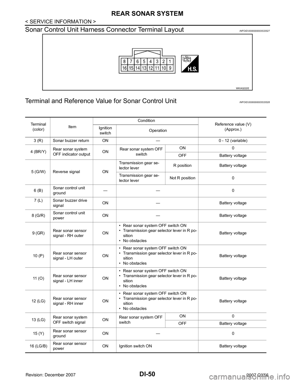
Sonar Control Unit Harness Connector Terminal Layout
INFOID:0000000003533527
Terminal and Reference Value for Sonar Control UnitINFOID:0000000003533528
WKIA5222E
Te r m i n a l
(color)ItemCondition
Reference value (V)
(Approx.) Ignition
switchOperation
3 (R) Sonar buzzer return ON — 0 - 12 (variable)
4 (BR/Y)Rear sonar system
OFF indicator outputONRear sonar system OFF
switch ON 0
OFF Battery voltage
5 (G/W) Reverse signal ONTransmission gear se-
lector leverR position Battery voltage
Transmission gear se-
lector leverNot R position 0
6 (B)Sonar control unit
ground —— 0
7 (L) Sonar buzzer drive
signalON — Battery voltage
8 (G/R)Sonar control unit
powerON — Battery voltage
9 (GR)Rear sonar sensor
signal - RH outerON• Rear sonar system OFF switch ON
• Transmission gear selector lever in R po-
sition
• No obstaclesBattery voltage
10 (P)Rear sonar sensor
signal - LH outerON• Rear sonar system OFF switch ON
• Transmission gear selector lever in R po-
sition
• No obstaclesBattery voltage
11 ( O )Rear sonar sensor
signal - LH innerON• Rear sonar system OFF switch ON
• Transmission gear selector lever in R po-
sition
• No obstaclesBattery voltage
12 (LG)Rear sonar sensor
signal - RH innerON• Rear sonar system OFF switch ON
• Transmission gear selector lever in R po-
sition
• No obstaclesBattery voltage
13 (LG)Rear sonar system
OFF switch signalONRear sonar system OFF
switchON 0
OFF Battery voltage
15 (Y)Rear sonar sensor
groundON — 0
16 (LG/B)Rear sonar sensor
powerON Ignition switch ON Battery voltage
Page 1065 of 3061
DI-54
< SERVICE INFORMATION >
REAR SONAR SYSTEM
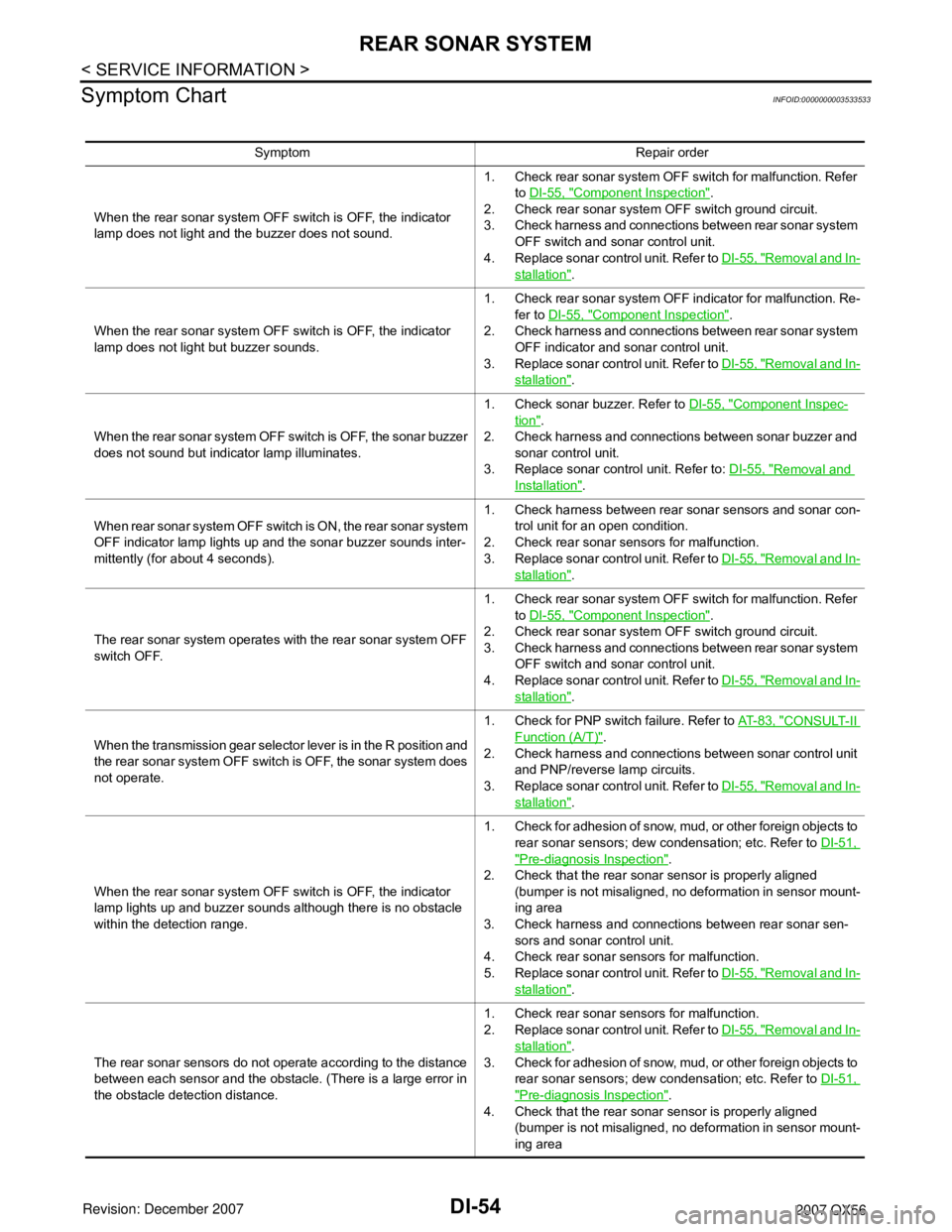
Symptom Chart
INFOID:0000000003533533
Symptom Repair order
When the rear sonar system OFF switch is OFF, the indicator
lamp does not light and the buzzer does not sound.1. Check rear sonar system OFF switch for malfunction. Refer
to DI-55, "
Component Inspection".
2. Check rear sonar system OFF switch ground circuit.
3. Check harness and connections between rear sonar system
OFF switch and sonar control unit.
4. Replace sonar control unit. Refer to DI-55, "
Removal and In-
stallation".
When the rear sonar system OFF switch is OFF, the indicator
lamp does not light but buzzer sounds.1. Check rear sonar system OFF indicator for malfunction. Re-
fer to DI-55, "
Component Inspection".
2. Check harness and connections between rear sonar system
OFF indicator and sonar control unit.
3. Replace sonar control unit. Refer to DI-55, "
Removal and In-
stallation".
When the rear sonar system OFF switch is OFF, the sonar buzzer
does not sound but indicator lamp illuminates.1. Check sonar buzzer. Refer to DI-55, "
Component Inspec-
tion".
2. Check harness and connections between sonar buzzer and
sonar control unit.
3. Replace sonar control unit. Refer to: DI-55, "
Removal and
Installation".
When rear sonar system OFF switch is ON, the rear sonar system
OFF indicator lamp lights up and the sonar buzzer sounds inter-
mittently (for about 4 seconds).1. Check harness between rear sonar sensors and sonar con-
trol unit for an open condition.
2. Check rear sonar sensors for malfunction.
3. Replace sonar control unit. Refer to DI-55, "
Removal and In-
stallation".
The rear sonar system operates with the rear sonar system OFF
switch OFF.1. Check rear sonar system OFF switch for malfunction. Refer
to DI-55, "
Component Inspection".
2. Check rear sonar system OFF switch ground circuit.
3. Check harness and connections between rear sonar system
OFF switch and sonar control unit.
4. Replace sonar control unit. Refer to DI-55, "
Removal and In-
stallation".
When the transmission gear selector lever is in the R position and
the rear sonar system OFF switch is OFF, the sonar system does
not operate.1. Check for PNP switch failure. Refer to AT- 8 3 , "
CONSULT-II
Function (A/T)".
2. Check harness and connections between sonar control unit
and PNP/reverse lamp circuits.
3. Replace sonar control unit. Refer to DI-55, "
Removal and In-
stallation".
When the rear sonar system OFF switch is OFF, the indicator
lamp lights up and buzzer sounds although there is no obstacle
within the detection range.1. Check for adhesion of snow, mud, or other foreign objects to
rear sonar sensors; dew condensation; etc. Refer to DI-51,
"Pre-diagnosis Inspection".
2. Check that the rear sonar sensor is properly aligned
(bumper is not misaligned, no deformation in sensor mount-
ing area
3. Check harness and connections between rear sonar sen-
sors and sonar control unit.
4. Check rear sonar sensors for malfunction.
5. Replace sonar control unit. Refer to DI-55, "
Removal and In-
stallation".
The rear sonar sensors do not operate according to the distance
between each sensor and the obstacle. (There is a large error in
the obstacle detection distance.1. Check rear sonar sensors for malfunction.
2. Replace sonar control unit. Refer to DI-55, "
Removal and In-
stallation".
3. Check for adhesion of snow, mud, or other foreign objects to
rear sonar sensors; dew condensation; etc. Refer to DI-51,
"Pre-diagnosis Inspection".
4. Check that the rear sonar sensor is properly aligned
(bumper is not misaligned, no deformation in sensor mount-
ing area
Page 1100 of 3061
PRECAUTIONS
EC-17
< SERVICE INFORMATION >
C
D
E
F
G
H
I
J
K
L
MA
EC
N
P O
PRECAUTIONS
Precaution for Supplemental Restraint System (SRS) "AIR BAG" and "SEAT BELT
PRE-TENSIONER"
INFOID:0000000003531580
The Supplemental Restraint System such as “AIR BAG” and “SEAT BELT PRE-TENSIONER”, used along
with a front seat belt, helps to reduce the risk or severity of injury to the driver and front passenger for certain
types of collision. This system includes seat belt switch inputs and dual stage front air bag modules. The SRS
system uses the seat belt switches to determine the front air bag deployment, and may only deploy one front
air bag, depending on the severity of a collision and whether the front occupants are belted or unbelted.
Information necessary to service the system safely is included in the SRS and SB section of this Service Man-
ual.
WARNING:
• To avoid rendering the SRS inoperative, which could increase the risk of personal injury or death in
the event of a collision which would result in air bag inflation, all maintenance must be performed by
an authorized NISSAN/INFINITI dealer.
• Improper maintenance, including incorrect removal and installation of the SRS, can lead to personal
injury caused by unintentional activation of the system. For removal of Spiral Cable and Air Bag
Module, see the SRS section.
• Do not use electrical test equipment on any circuit related to the SRS unless instructed to in this
Service Manual. SRS wiring harnesses can be identified by yellow and/or orange harnesses or har-
ness connectors.
On Board Diagnosis (OBD) System of Engine and A/TINFOID:0000000003531581
The ECM has an on board diagnostic system. It will light up the malfunction indicator lamp (MIL) to warn the
driver of a malfunction causing emission deterioration.
CAUTION:
• Be sure to turn the ignition switch OFF and disconnect the negative battery cable before any repair
or inspection work. The open/short circuit of related switches, sensors, solenoid valves, etc. will
cause the MIL to light up.
• Be sure to connect and lock the connectors securely after work. A loose (unlocked) connector will
cause the MIL to light up due to the open circuit. (Be sure the connector is free from water, grease,
dirt, bent terminals, etc.)
• Certain systems and components, especially those related to OBD, may use a new style slide-lock-
ing type harness connector. For description and how to disconnect, refer to PG-66
.
• Be sure to route and secure the harnesses properly after work. The interference of the harness with
a bracket, etc. may cause the MIL to light up due to the short circuit.
• Be sure to connect rubber tubes properly after work. A misconnected or disconnected rubber tube
may cause the MIL to light up due to the malfunction of the EVAP system or fuel injection system,
etc.
• Be sure to erase the unnecessary malfunction information (repairs completed) from the ECM and
TCM (Transmission control module) before returning the vehicle to the customer.
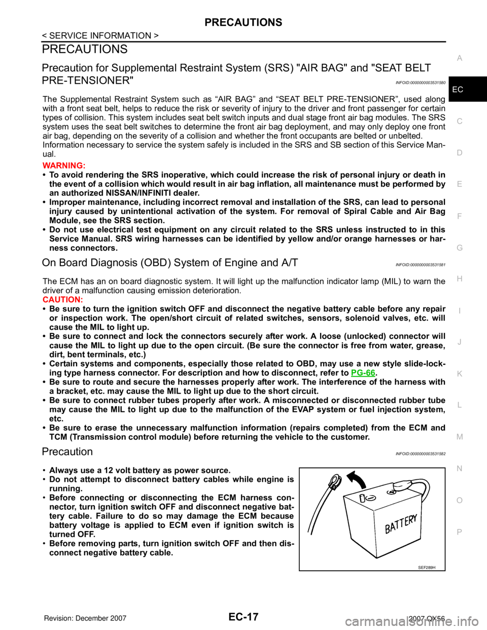
PrecautionINFOID:0000000003531582
•Always use a 12 volt battery as power source.
•Do not attempt to disconnect battery cables while engine is
running.
•Before connecting or disconnecting the ECM harness con-
nector, turn ignition switch OFF and disconnect negative bat-
tery cable. Failure to do so may damage the ECM because
battery voltage is applied to ECM even if ignition switch is
turned OFF.
•Before removing parts, turn ignition switch OFF and then dis-
connect negative battery cable.
SEF289H
Page 1115 of 3061
EC-32
< SERVICE INFORMATION >
CAN COMMUNICATION
CAN COMMUNICATION
System DescriptionINFOID:0000000003531593
CAN (Controller Area Network) is a serial communication line for real time application. It is an on-vehicle mul-
tiplex communication line with high data communication speed and excellent error detection ability. Many elec-
tronic control units are equipped onto a vehicle, and each control unit shares information and links with other
control units during operation (not independent). In CAN communication, control units are connected with 2
communication lines (CAN H line, CAN L line) allowing a high rate of information transmission with less wiring.
Each control unit transmits/receives data but selectively reads required data only.
Refer to LAN-44, "
CAN System Specification Chart", about CAN communication for detail.
Page 1143 of 3061
EC-60
< SERVICE INFORMATION >
ON BOARD DIAGNOSTIC (OBD) SYSTEM
• Sea level
• Flat road
• Ambient air temperature: 20 - 30°C (68 - 86°F)
• Diagnosis is performed as quickly as possible under normal conditions.
Under different conditions [For example: ambient air temperature other than 20 - 30°C (68 - 86°F)], diagno-
sis may also be performed.
Pattern 1:
•The engine is started at the engine coolant temperature of −10 to 35°C (14 to 95°F)
(where the voltage between the ECM terminal 73 and ground is 3.0 - 4.3V).
•The engine must be operated at idle speed until the engine coolant temperature is greater than 70°C
(158°F) (where the voltage between the ECM terminal 73 and ground is lower than 1.4V).
•The engine is started at the fuel tank temperature of warmer than 0°C (32°F) (where the voltage
between the ECM terminal 107 and ground is less than 4.1V).
Pattern 2:
• When steady-state driving is performed again even after it is interrupted, each diagnosis can be conducted.
In this case, the time required for diagnosis may be extended.
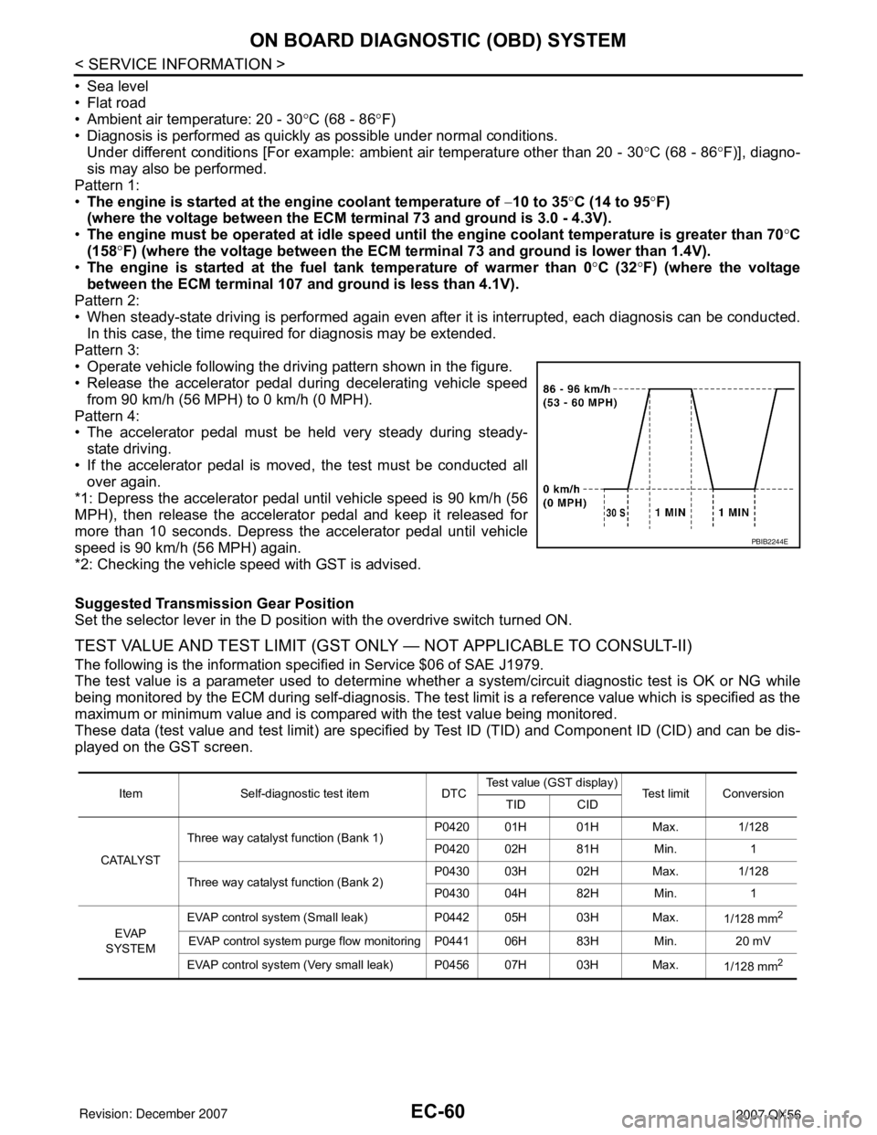
Pattern 3:
• Operate vehicle following the driving pattern shown in the figure.
• Release the accelerator pedal during decelerating vehicle speed
from 90 km/h (56 MPH) to 0 km/h (0 MPH).
Pattern 4:
• The accelerator pedal must be held very steady during steady-
state driving.
• If the accelerator pedal is moved, the test must be conducted all
over again.
*1: Depress the accelerator pedal until vehicle speed is 90 km/h (56
MPH), then release the accelerator pedal and keep it released for
more than 10 seconds. Depress the accelerator pedal until vehicle
speed is 90 km/h (56 MPH) again.
*2: Checking the vehicle speed with GST is advised.
Suggested Transmission Gear Position
Set the selector lever in the D position with the overdrive switch turned ON.
TEST VALUE AND TEST LIMIT (GST ONLY — NOT APPLICABLE TO CONSULT-II)
The following is the information specified in Service $06 of SAE J1979.
The test value is a parameter used to determine whether a system/circuit diagnostic test is OK or NG while
being monitored by the ECM during self-diagnosis. The test limit is a reference value which is specified as the
maximum or minimum value and is compared with the test value being monitored.
These data (test value and test limit) are specified by Test ID (TID) and Component ID (CID) and can be dis-
played on the GST screen.
PBIB2244E
Item Self-diagnostic test item DTCTest value (GST display)
Test limit Conversion
TID CID
CATALYSTThree way catalyst function (Bank 1)P0420 01H 01H Max. 1/128
P0420 02H 81H Min. 1
Three way catalyst function (Bank 2)P0430 03H 02H Max. 1/128
P0430 04H 82H Min. 1
EVAP
SYSTEMEVAP control system (Small leak) P0442 05H 03H Max.
1/128 mm
2
EVAP control system purge flow monitoring P0441 06H 83H Min. 20 mV
EVAP control system (Very small leak) P0456 07H 03H Max.
1/128 mm
2