2007 INFINITI QX56 ignition
[x] Cancel search: ignitionPage 2932 of 3061
TF-110
< SERVICE INFORMATION >
TROUBLE DIAGNOSIS FOR SYMPTOMS
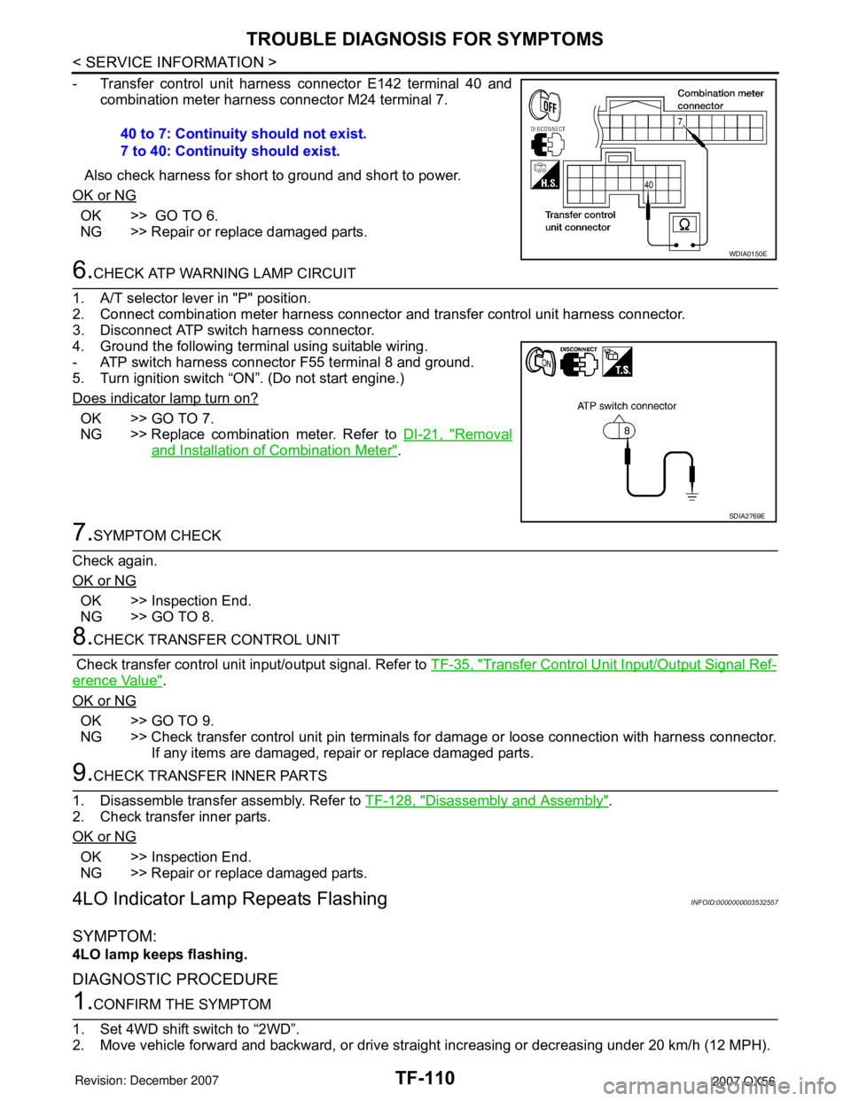
- Transfer control unit harness connector E142 terminal 40 and
combination meter harness connector M24 terminal 7.
Also check harness for short to ground and short to power.
OK or NG
OK >> GO TO 6.
NG >> Repair or replace damaged parts.
6.CHECK ATP WARNING LAMP CIRCUIT
1. A/T selector lever in "P" position.
2. Connect combination meter harness connector and transfer control unit harness connector.
3. Disconnect ATP switch harness connector.
4. Ground the following terminal using suitable wiring.
- ATP switch harness connector F55 terminal 8 and ground.
5. Turn ignition switch “ON”. (Do not start engine.)
Does indicator lamp turn on?
OK >> GO TO 7.
NG >> Replace combination meter. Refer to DI-21, "
Removal
and Installation of Combination Meter".
7.SYMPTOM CHECK
Check again.
OK or NG
OK >> Inspection End.
NG >> GO TO 8.
8.CHECK TRANSFER CONTROL UNIT
Check transfer control unit input/output signal. Refer to TF-35, "
Transfer Control Unit Input/Output Signal Ref-
erence Value".
OK or NG
OK >> GO TO 9.
NG >> Check transfer control unit pin terminals for damage or loose connection with harness connector.
If any items are damaged, repair or replace damaged parts.
9.CHECK TRANSFER INNER PARTS
1. Disassemble transfer assembly. Refer to TF-128, "
Disassembly and Assembly".
2. Check transfer inner parts.
OK or NG
OK >> Inspection End.
NG >> Repair or replace damaged parts.
4LO Indicator Lamp Repeats FlashingINFOID:0000000003532557
SYMPTOM:
4LO lamp keeps flashing.
DIAGNOSTIC PROCEDURE
1.CONFIRM THE SYMPTOM
1. Set 4WD shift switch to “2WD”.
2. Move vehicle forward and backward, or drive straight increasing or decreasing under 20 km/h (12 MPH). 40 to 7: Continuity should not exist.
7 to 40: Continuity should exist.
WDIA0150E
SDIA2769E
Page 2934 of 3061
TF-112
< SERVICE INFORMATION >
TROUBLE DIAGNOSIS FOR SYMPTOMS
YES >> Inspection End.
NO >> GO TO 3.
3.CHECK TRANSFER FLUID TEMPERATURE
Perform trouble diagnosis for transfer fluid temperature system. Refer to TF-90, "
Transfer Fluid Temperature".
OK or NG
OK >> GO TO 4.
NG >> Repair or replace damaged parts.
4.SYMPTOM CHECK
Check again.
OK or NG
OK >> Inspection End.
NG >> GO TO 5.
5.CHECK TRANSFER CONTROL UNIT
Check transfer control unit input/output signal. Refer to TF-35, "
Transfer Control Unit Input/Output Signal Ref-
erence Value".
OK or NG
OK >> Inspection End.
NG >> Check transfer control unit pin terminals for damage or loose connection with harness connector.
If any items are damaged, repair or replace damaged parts.
4WD Warning Lamp Flashes SlowlyINFOID:0000000003532559
SYMPTOM:
While driving, 4WD warning lamp flashes slowly. (When continuing to flash until turning ignition
switch OFF.)
NOTE:
Slow flashing: 1 time/2 seconds
DIAGNOSTIC PROCEDURE
1.CHECK TIRE
Check the following.
• Tire pressure
• Wear condition
• Longitudinal tire size (There is no difference between longitudinal tires.)
OK or NG
OK >> GO TO 2.
NG >> Repair or replace damaged parts.
2.CHECK TRANSFER FLUID TEMPERATURE
Perform trouble diagnosis for transfer fluid temperature system. Refer to TF-90, "
Transfer Fluid Temperature".
OK or NG
OK >> GO TO 3.
NG >> Repair or replace damaged parts.
3.CHECK CLUTCH PRESSURE SWITCH
Perform trouble diagnosis for clutch pressure switch system. Refer to TF-92, "
Clutch Pressure Switch".
OK or NG
OK >> GO TO 4.
NG >> Repair or replace damaged parts.
4.SYMPTOM CHECK
Check again.
OK or NG
OK >> Inspection End.
Page 2937 of 3061
TRANSFER CONTROL UNIT
TF-115
< SERVICE INFORMATION >
C
E
F
G
H
I
J
K
L
MA
B
TF
N
O
P
TRANSFER CONTROL UNIT
Removal and InstallationINFOID:0000000003532562
REMOVAL
1. Set transfer state as 2WD when 4WD shift switch is at 2WD, or as AUTO when 4WD shift switch is at
AUTO.
CAUTION:
When removing transfer control unit, transfer state must be at 2WD or AUTO.
2. Turn the ignition switch OFF and disconnect negative battery terminal.
3. Remove the glove box assembly. Refer to IP-10, "
Removal and Installation".
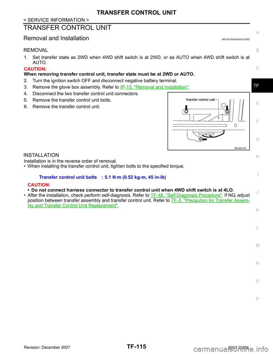
4. Disconnect the two transfer control unit connectors.
5. Remove the transfer control unit bolts.
6. Remove the transfer control unit.
INSTALLATION
Installation is in the reverse order of removal.
• When installing the transfer control unit, tighten bolts to the specified torque.
CAUTION:
• Do not connect harness connector to transfer control unit when 4WD shift switch is at 4LO.
• After the installation, check perform self-diagnosis. Refer to TF-48, "
Self-Diagnosis Procedure". If NG, adjust
position between transfer assembly and transfer control unit. Refer to TF-3, "
Precaution for Transfer Assem-
bly and Transfer Control Unit Replacement".
BDIA0014E
Transfer control unit bolts : 5.1 N·m (0.52 kg-m, 45 in-lb)
Page 2990 of 3061

WT-1
SUSPENSION
C
D
F
G
H
I
J
K
L
M
SECTION WT
A
B
WT
N
O
PCONTENTS
ROAD WHEELS & TIRES
SERVICE INFORMATION ............................2
PRECAUTIONS ...................................................2
Precaution for Supplemental Restraint System
(SRS) "AIR BAG" and "SEAT BELT PRE-TEN-
SIONER" ...................................................................
2
PREPARATION ...................................................3
Special Service Tool .................................................3
Commercial Service Tool ..........................................3
NOISE, VIBRATION AND HARSHNESS
(NVH) TROUBLESHOOTING .............................
4
NVH Troubleshooting Chart ......................................4
WHEEL ................................................................5
Inspection ..................................................................5
WHEEL AND TIRE ASSEMBLY .........................6
Balancing Wheels .....................................................6
Rotation .....................................................................7
LOW TIRE PRESSURE WARNING SYSTEM .....8
System Component ...................................................8
System Description ...................................................8
CAN COMMUNICATION ....................................10
System Description .................................................10
TROUBLE DIAGNOSIS .....................................11
Wiring Diagram- T/WARN - .....................................11
Terminal and Reference Value (BCM) ....................12
ID Registration Procedure .......................................12
Transmitter Wake Up Operation .............................14
CONSULT-II Function (BCM) ..................................15
Self-Diagnosis .........................................................15
How to Perform Trouble Diagnosis for Quick and
Accurate Repair .......................................................
17
Preliminary Check ...................................................18
Flash Code/Symptom Chart ....................................18
TROUBLE DIAGNOSIS FOR SELF-DIAG-
NOSTIC ITEMS .................................................
20
Data from Transmitter Not Being Received .............20
Transmitter Malfunction ...........................................20
Transmitter Pressure Malfunction ............................21
Vehicle Speed Signal ..............................................21
Ignition Signal ..........................................................22
TROUBLE DIAGNOSIS FOR SYMPTOMS ......23
Low Tire Pressure Warning Lamp Does Not Come
On When Ignition Switch Is Turned On ...................
23
Low Tire Pressure Warning Lamp Stays On When
Ignition Switch Is Turned On ...................................
23
Low Tire Pressure Warning Lamp Flashes When
Ignition Switch Is Turned On ...................................
24
Hazard Warning Lamps Flash When Ignition
Switch Is Turned On ................................................
25
"TIRE PRESSURE" Information in Display Unit
Does Not Exist .........................................................
25
ID Registration Cannot Be Completed ....................25
REMOVAL AND INSTALLATION .....................26
Transmitter (Pressure Sensor) ................................26
SERVICE DATA AND SPECIFICATIONS
(SDS) .................................................................
28
Road Wheel .............................................................28
Tire ..........................................................................28
Page 2997 of 3061

WT-8
< SERVICE INFORMATION >
LOW TIRE PRESSURE WARNING SYSTEM
LOW TIRE PRESSURE WARNING SYSTEM
System ComponentINFOID:0000000003532692
System DescriptionINFOID:0000000003532693
BODY CONTROL MODULE (BCM)
The BCM is shown with the lower instrument panel LH removed. The
BCM reads the air pressure signal received by the remote keyless
entry receiver, and controls the low tire pressure warning lamp as
shown below. It also has a self-diagnosis function to detect a system
malfunction.
TRANSMITTER
A sensor-transmitter integrated with a valve is installed in each
wheel, and transmits a detected air pressure signal in the form of a
radio wave. The radio signal is received by the remote keyless entry
receiver.
WEIA0081E
Condition Low tire pressure warning lamp
System normal On for 1 second after ignition ON
Tire less than 193 kPa (2.0 kg/cm
2 , 28 psi)
[Flat tire]ON
Low tire pressure warning system malfunc-
tionAfter key ON, flashes once per sec-
ond for 1 minute, then stays ON
LEIA0068E
WEIA0137E
Page 2998 of 3061
LOW TIRE PRESSURE WARNING SYSTEM
WT-9
< SERVICE INFORMATION >
C
D
F
G
H
I
J
K
L
MA
B
WT
N
O
P
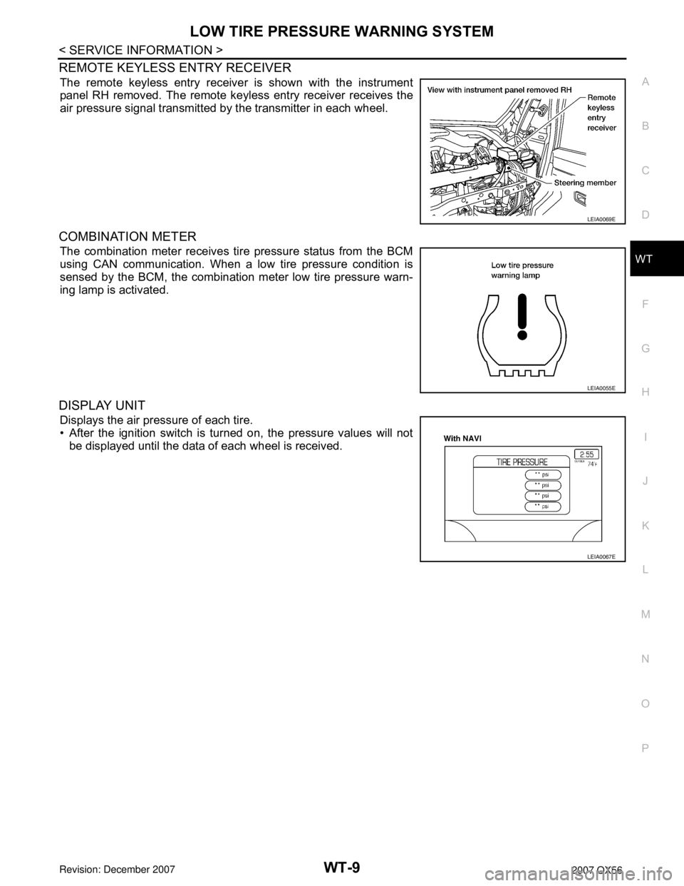
REMOTE KEYLESS ENTRY RECEIVER
The remote keyless entry receiver is shown with the instrument
panel RH removed. The remote keyless entry receiver receives the
air pressure signal transmitted by the transmitter in each wheel.
COMBINATION METER
The combination meter receives tire pressure status from the BCM
using CAN communication. When a low tire pressure condition is
sensed by the BCM, the combination meter low tire pressure warn-
ing lamp is activated.
DISPLAY UNIT
Displays the air pressure of each tire.
• After the ignition switch is turned on, the pressure values will not
be displayed until the data of each wheel is received.
LEIA0069E
LEIA0055E
LEIA0067E
Page 3003 of 3061
WT-14
< SERVICE INFORMATION >
TROUBLE DIAGNOSIS
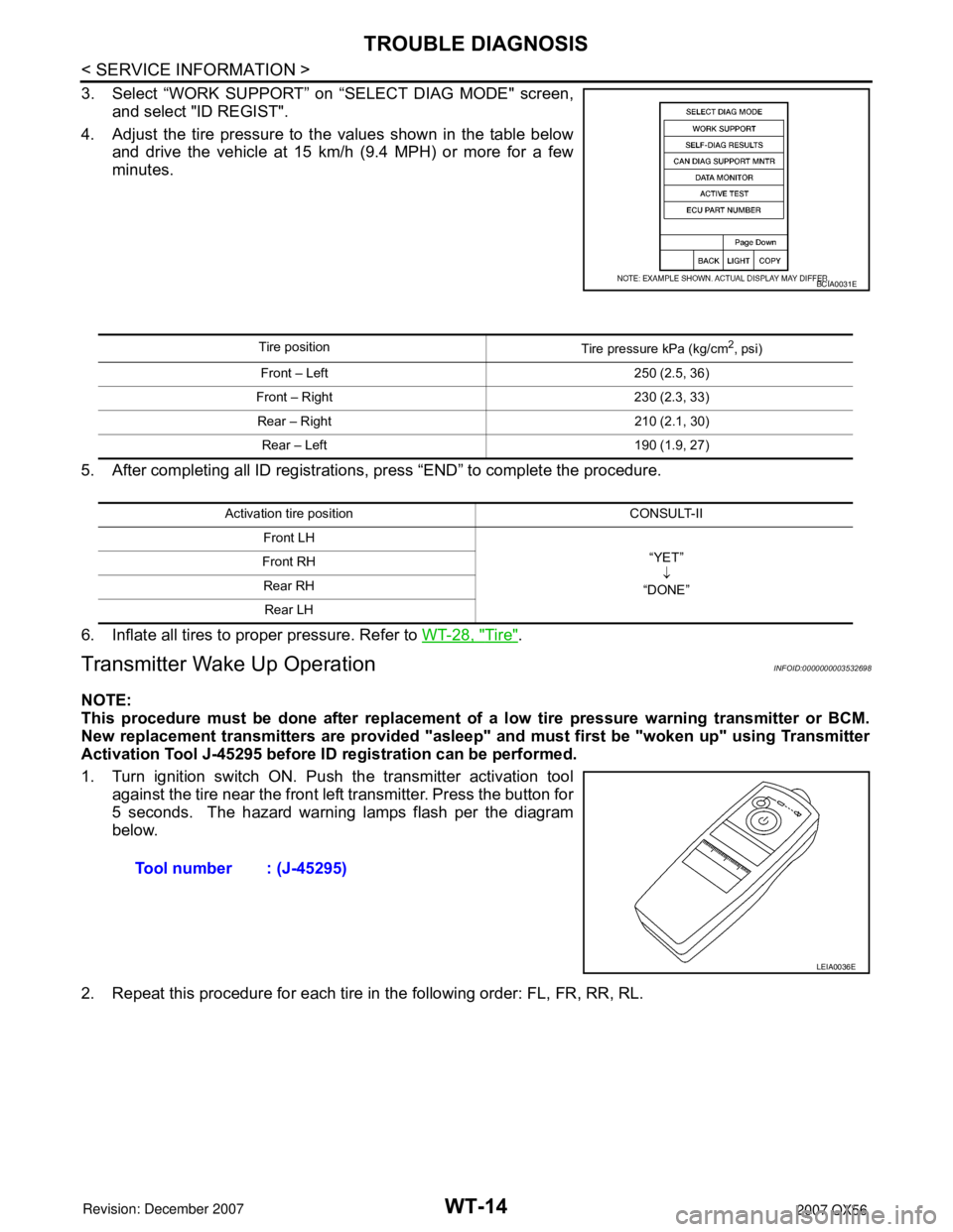
3. Select “WORK SUPPORT” on “SELECT DIAG MODE" screen,
and select "ID REGIST".
4. Adjust the tire pressure to the values shown in the table below
and drive the vehicle at 15 km/h (9.4 MPH) or more for a few
minutes.
5. After completing all ID registrations, press “END” to complete the procedure.
6. Inflate all tires to proper pressure. Refer to WT-28, "
Tire".
Transmitter Wake Up OperationINFOID:0000000003532698
NOTE:
This procedure must be done after replacement of a low tire pressure warning transmitter or BCM.
New replacement transmitters are provided "asleep" and must first be "woken up" using Transmitter
Activation Tool J-45295 before ID registration can be performed.
1. Turn ignition switch ON. Push the transmitter activation tool
against the tire near the front left transmitter. Press the button for
5 seconds. The hazard warning lamps flash per the diagram
below.
2. Repeat this procedure for each tire in the following order: FL, FR, RR, RL.
BCIA0031E
Tire position
Tire pressure kPa (kg/cm2, psi)
Front – Left 250 (2.5, 36)
Front – Right 230 (2.3, 33)
Rear – Right 210 (2.1, 30)
Rear – Left 190 (1.9, 27)
Activation tire position CONSULT-II
Front LH
“YET”
↓
“DONE” Front RH
Rear RH
Rear LH
Tool number : (J-45295)
LEIA0036E
Page 3005 of 3061

WT-16
< SERVICE INFORMATION >
TROUBLE DIAGNOSIS
× : Applicable
– : Not applicable
Self-Diagnostic Results Mode
NOTE:
Before performing the self-diagnosis, be sure to register the ID or else the actual malfunction location may be different from that dis-
played on CONSULT-II.
Data Monitor Mode
Rear - Left transmitter××
Rear - Right transmitter××
Warning lamp —×
Vehicle speed××
Buzzer (in combination meter) —×
CAN Communication×× ITEM SELF-DIAGNOSTIC RESULTS DATA MONITOR
Diagnostic item
Diagnostic item is detected when ···Reference
page Program card UED06A or
earlierProgram card UED06B or later
FLAT - TIRE - FL [C1704]
FLAT - TIRE - FR [C1705]
FLAT - TIRE - RR [C1706]
FLAT - TIRE - RL [C1707]LOW - PRESSURE - FL [C1704]
LOW - PRESSURE - FR [C1705]
LOW - PRESSURE - RR [C1706]
LOW - PRESSURE - RL [C1707]FL tire pressure 193 kPa (2.0 kg/cm
2 , 28 psi) or less
FR tire pressure 193 kPa (2.0 kg/cm2 , 28 psi) or less
RR tire pressure 193 kPa (2.0 kg/cm2 , 28 psi) or less
RL tire pressure 193 kPa (2.0 kg/cm2 , 28 psi) or less—
[NO-DATA] - FL [C1708]
[NO-DATA] - FR [C1709]
[NO-DATA] - RR [C1710]
[NO-DATA] - RL [C1711]Data from FL transmitter cannot be received.
Data from FR transmitter cannot be received.
Data from RR transmitter cannot be received.
Data from RL transmitter cannot be received.WT-20
[CHECKSUM- ERR] - FL [C1712]
[CHECKSUM- ERR] - FR [C1713]
[CHECKSUM- ERR] - RR [C1714]
[CHECKSUM- ERR] - RL [C1715]Checksum data from FL transmitter is malfunctioning.
Checksum data from FR transmitter is malfunctioning.
Checksum data from RR transmitter is malfunctioning.
Checksum data from RL transmitter is malfunctioning.WT-20
[PRESSDATA- ERR] - FL [C1716]
[PRESSDATA- ERR] - FR [C1717]
[PRESSDATA- ERR] - RR [C1718]
[PRESSDATA- ERR] - RL [C1719]Air pressure data from FL transmitter is malfunctioning.
Air pressure data from FR transmitter is malfunctioning.
Air pressure data from RR transmitter is malfunctioning.
Air pressure data from RL transmitter is malfunctioning.WT-21
[CODE- ERR] - FL [C1720]
[CODE- ERR] - FR [C1721]
[CODE- ERR] - RR [C1722]
[CODE- ERR] - RL [C1723]Function code data from FL transmitter is malfunctioning.
Function code data from FR transmitter is malfunctioning.
Function code data from RR transmitter is malfunctioning.
Function code data from RL transmitter is malfunctioning.WT-20
[BATT - VOLT - LOW] - FL [C1724]
[BATT - VOLT - LOW] - FR [C1725]
[BATT - VOLT - LOW] - RR [C1726]
[BATT - VOLT - LOW] - RL [C1727]Battery voltage of FL transmitter drops.
Battery voltage of FR transmitter drops.
Battery voltage of RR transmitter drops.
Battery voltage of RL transmitter drops.WT-20
VHCL_SPEED_SIG_ERR [C1729] Vehicle speed signal is in error.WT-21
IGN_CIRCUIT_OPEN [C1735] Vehicle ignition signal is in error.WT-22
MONITOR CONDITION SPECIFICATION
VHCL SPEED Drive vehicle. Vehicle speed (km/h or MPH)
AIR PRESS FL
AIR PRESS FR
AIR PRESS RR
AIR PRESS RL• Drive vehicle for a few minutes.
Tire pressure (kPa or psi) or
• Ignition switch ON and activation tool
is transmitting activation signals.