Page 3006 of 3061
TROUBLE DIAGNOSIS
WT-17
< SERVICE INFORMATION >
C
D
F
G
H
I
J
K
L
MA
B
WT
N
O
P
NOTE:
Before performing the self-diagnosis, be sure to register the ID, or the actual malfunction location may be different from that displayed on
CONSULT-II.
How to Perform Trouble Diagnosis for Quick and Accurate RepairINFOID:0000000003532701
INTRODUCTION
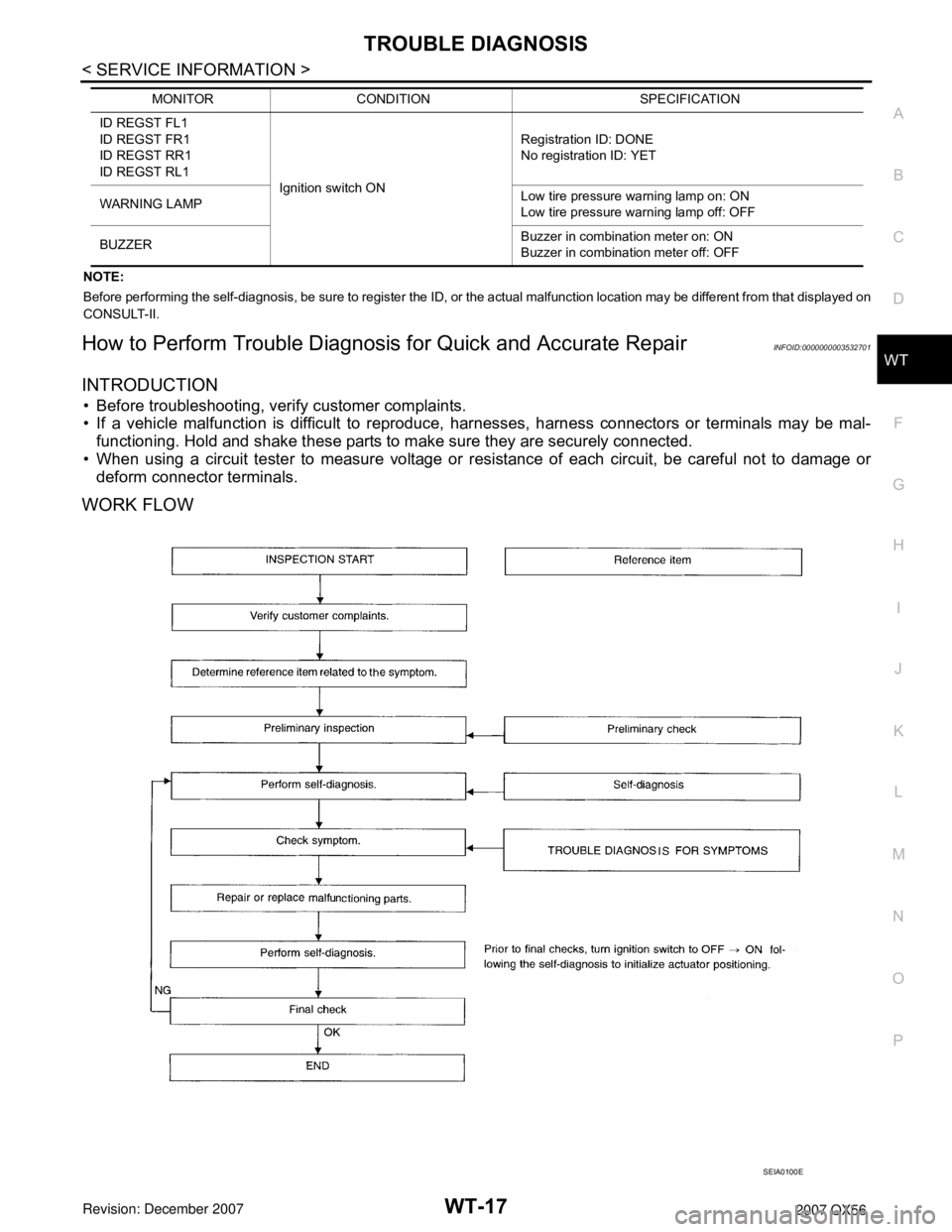
• Before troubleshooting, verify customer complaints.
• If a vehicle malfunction is difficult to reproduce, harnesses, harness connectors or terminals may be mal-
functioning. Hold and shake these parts to make sure they are securely connected.
• When using a circuit tester to measure voltage or resistance of each circuit, be careful not to damage or
deform connector terminals.
WORK FLOW
ID REGST FL1
ID REGST FR1
ID REGST RR1
ID REGST RL1
Ignition switch ONRegistration ID: DONE
No registration ID: YET
WARNING LAMPLow tire pressure warning lamp on: ON
Low tire pressure warning lamp off: OFF
BUZZERBuzzer in combination meter on: ON
Buzzer in combination meter off: OFF MONITOR CONDITION SPECIFICATION
SEIA0100E
Page 3007 of 3061
WT-18
< SERVICE INFORMATION >
TROUBLE DIAGNOSIS
Preliminary Check
INFOID:0000000003532702
BASIC INSPECTION
1.CHECK ALL TIRE PRESSURES
Check all tire pressures. Refer to WT-28, "
Tire".
OK or NG
OK >> GO TO 2.
NG >> Adjust tire pressure to specified value.
2.CHECK LOW TIRE PRESSURE WARNING LAMP ACTIVATION
Check low tire pressure warning lamp activation.
Does warning lamp activate for 1 second when ignition switch is turned ON?
YES >> GO TO 3.
NO >> GO TO WT-23, "
Low Tire Pressure Warning Lamp Does Not Come On When Ignition Switch Is
Turned On".
3.CHECK BCM CONNECTOR
1. Disconnect BCM harness connector.
2. Check terminals for damage or loose connection.
3. Reconnect harness connector.
OK or NG
OK >> GO TO 4.
NG >> Repair or replace damaged parts.
4.CHECK TRANSMITTER ACTIVATION TOOL
Check transmitter activation tool battery.
OK or NG
OK >> Carry out self-diagnosis.
NG >> Replace battery in transmitter activation tool.
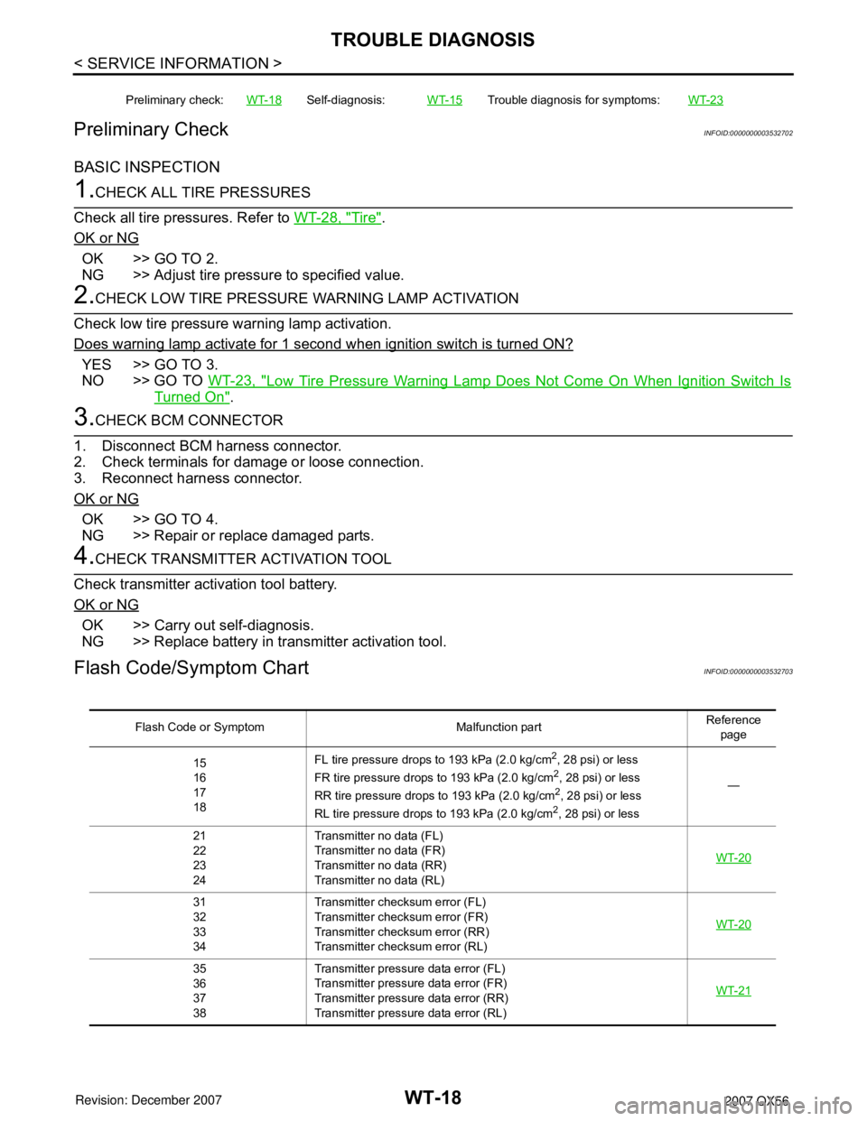
Flash Code/Symptom ChartINFOID:0000000003532703
Preliminary check:WT-18Self-diagnosis:WT-15Trouble diagnosis for symptoms:WT-23
Flash Code or Symptom Malfunction partReference
page
15
16
17
18FL tire pressure drops to 193 kPa (2.0 kg/cm
2, 28 psi) or less
FR tire pressure drops to 193 kPa (2.0 kg/cm2, 28 psi) or less
RR tire pressure drops to 193 kPa (2.0 kg/cm2, 28 psi) or less
RL tire pressure drops to 193 kPa (2.0 kg/cm2, 28 psi) or less—
21
22
23
24Transmitter no data (FL)
Transmitter no data (FR)
Transmitter no data (RR)
Transmitter no data (RL)WT-20
31
32
33
34Transmitter checksum error (FL)
Transmitter checksum error (FR)
Transmitter checksum error (RR)
Transmitter checksum error (RL)WT-20
35
36
37
38Transmitter pressure data error (FL)
Transmitter pressure data error (FR)
Transmitter pressure data error (RR)
Transmitter pressure data error (RL)WT-21
Page 3008 of 3061
TROUBLE DIAGNOSIS
WT-19
< SERVICE INFORMATION >
C
D
F
G
H
I
J
K
L
MA
B
WT
N
O
P
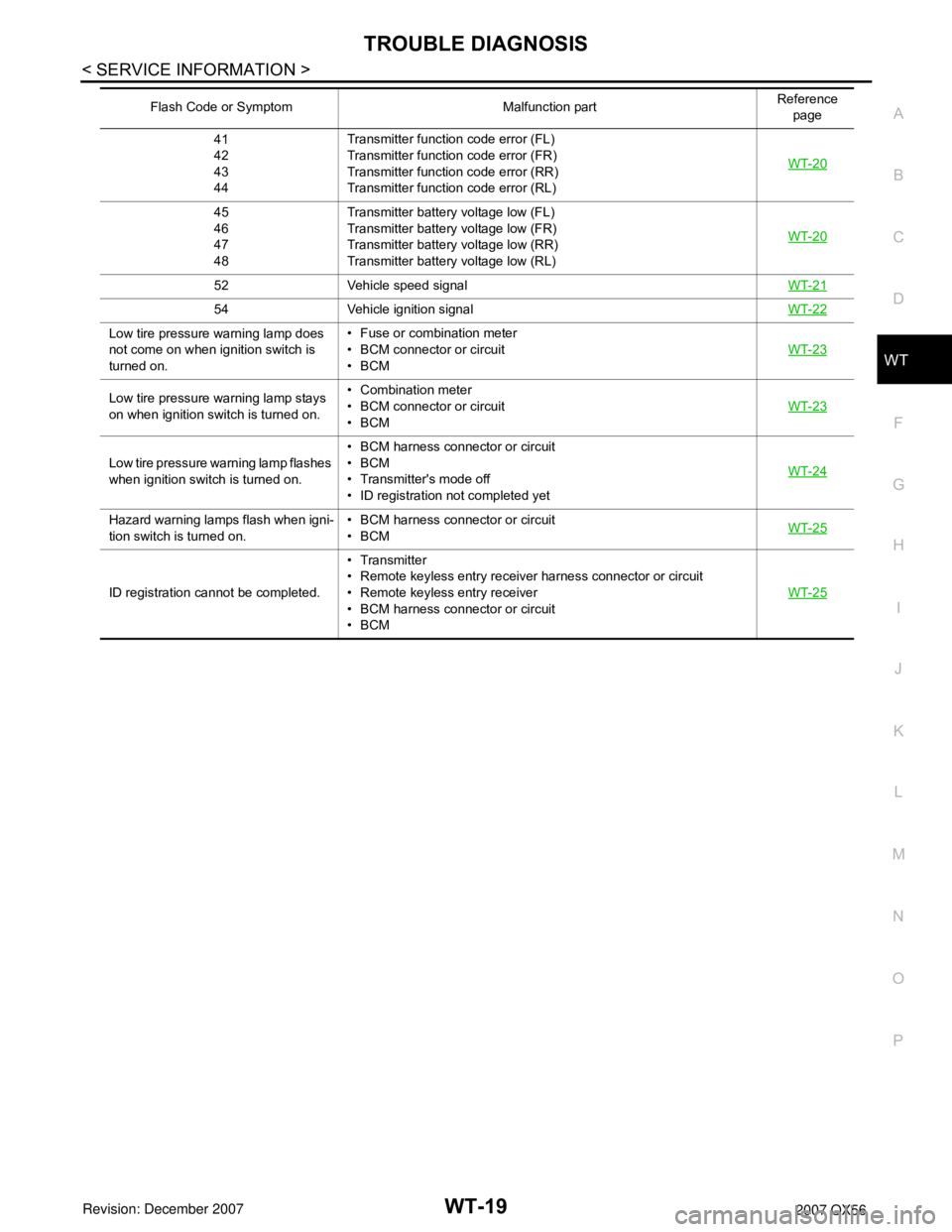
41
42
43
44Transmitter function code error (FL)
Transmitter function code error (FR)
Transmitter function code error (RR)
Transmitter function code error (RL)WT-20
45
46
47
48Transmitter battery voltage low (FL)
Transmitter battery voltage low (FR)
Transmitter battery voltage low (RR)
Transmitter battery voltage low (RL)WT-20
52 Vehicle speed signalWT-21
54 Vehicle ignition signalWT-22
Low tire pressure warning lamp does
not come on when ignition switch is
turned on.• Fuse or combination meter
• BCM connector or circuit
•BCM WT-23
Low tire pressure warning lamp stays
on when ignition switch is turned on.• Combination meter
• BCM connector or circuit
•BCMWT-23
Low tire pressure warning lamp flashes
when ignition switch is turned on.• BCM harness connector or circuit
•BCM
• Transmitter's mode off
• ID registration not completed yetWT-24
Hazard warning lamps flash when igni-
tion switch is turned on.• BCM harness connector or circuit
•BCMWT-25
ID registration cannot be completed.• Transmitter
• Remote keyless entry receiver harness connector or circuit
• Remote keyless entry receiver
• BCM harness connector or circuit
•BCMWT-25
Flash Code or Symptom Malfunction partReference
page
Page 3011 of 3061
WT-22
< SERVICE INFORMATION >
TROUBLE DIAGNOSIS FOR SELF-DIAGNOSTIC ITEMS
Ignition Signal
INFOID:0000000003585170
MALFUNCTION CODE NO. 54 (DTC C1735)
1.CAN IGNITION SIGNAL
Check BCM IGN RLY signal with CONSULT-II.
Are the inspection results normal with the ignition switch ON?
YES >> GO TO 2.
NO >> Check CAN system.
2.BCM POWER SUPPLY
Check BCM power supply (ignition ON). Refer to BCS-15, "
BCM Power Supply and Ground Circuit Inspec-
tion".
Is the power supply with the ignition switch ON normal?
YES >> GO TO 3.
NO >> Repair power supply as necessary.
3.DRIVE VEHICLE
Clear DTC and then test drive the vehicle and check the low tire pressure warning lamp.
Does the vehicle operate without any low tire pressure warning lamp?
YES >> Inspection End.
NO >> Replace BCM. Refer to BCS-24, "
BCM".
Page 3012 of 3061
TROUBLE DIAGNOSIS FOR SYMPTOMS
WT-23
< SERVICE INFORMATION >
C
D
F
G
H
I
J
K
L
MA
B
WT
N
O
P
TROUBLE DIAGNOSIS FOR SYMPTOMS
Low Tire Pressure Warning Lamp Does Not Come On When Ignition Switch Is Turned
On
INFOID:0000000003532708
DIAGNOSTIC PROCEDURE
1.SELF-DIAGNOSTIC RESULT CHECK
Using CONSULT-II, check display contents in self-diagnostic results.
Is "CAN COMM CIRCUIT" displayed in the self-diagnosis display items?
YES >> Malfunction in CAN communication system. GO TO LAN-40.
NO >> GO TO 2.
2.CHECK COMBINATION METER
Check combination meter operation. Refer to DI-12, "
Self-Diagnosis Mode of Combination Meter".
Inspection results OK?
OK >> GO TO 3.
NG >> Replace combination meter. Refer to IP-10, "
Removal and Installation".
3.CHECK LOW TIRE PRESSURE WARNING LAMP
Disconnect BCM harness connector.
Does the low tire pressure warning lamp activate?
YES >> Replace BCM. Refer to BCS-24, "BCM".
NO >> Check combination meter operation. Refer to DI-12, "
Self-Diagnosis Mode of Combination
Meter".
Low Tire Pressure Warning Lamp Stays On When Ignition Switch Is Turned On
INFOID:0000000003532709
DIAGNOSTIC PROCEDURE
1.CHECK BCM CONNECTORS
1. Turn ignition switch OFF.
2. Disconnect BCM harness connectors M18 and M20.
3. Check terminals for damage or loose connections.
Inspection results OK?
OK >> GO TO 2.
NG >> Repair or replace damaged parts.
2.CHECK BCM POWER SUPPLY CIRCUIT (BAT)
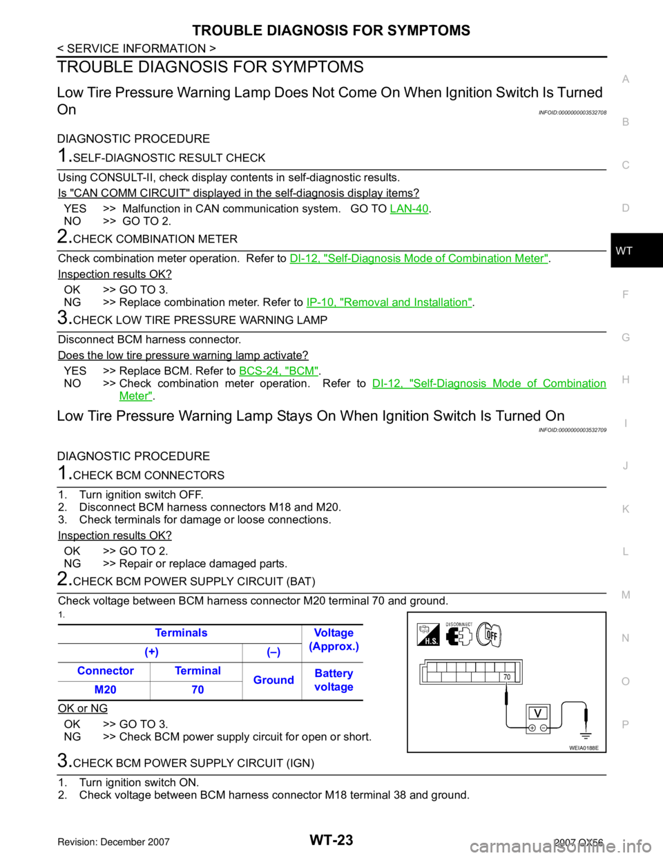
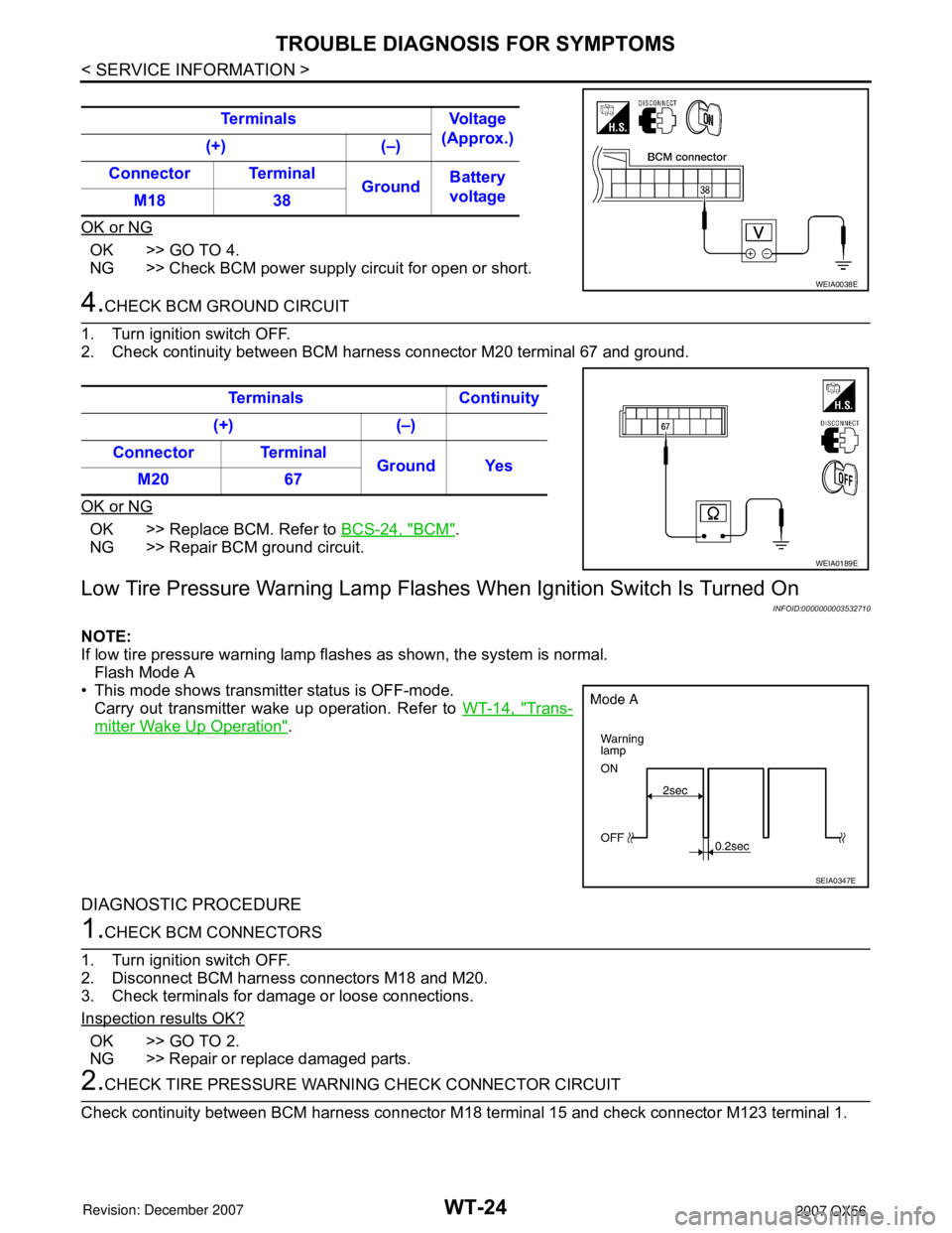
Check voltage between BCM harness connector M20 terminal 70 and ground.
1.
OK or NG
OK >> GO TO 3.
NG >> Check BCM power supply circuit for open or short.
3.CHECK BCM POWER SUPPLY CIRCUIT (IGN)
1. Turn ignition switch ON.
2. Check voltage between BCM harness connector M18 terminal 38 and ground.Terminals Voltage
(Approx.)
(+) (–)
Connector Terminal
GroundBattery
voltage
M20 70
WEIA0188E
Page 3013 of 3061
WT-24
< SERVICE INFORMATION >
TROUBLE DIAGNOSIS FOR SYMPTOMS
OK or NG
OK >> GO TO 4.
NG >> Check BCM power supply circuit for open or short.
4.CHECK BCM GROUND CIRCUIT
1. Turn ignition switch OFF.
2. Check continuity between BCM harness connector M20 terminal 67 and ground.
OK or NG
OK >> Replace BCM. Refer to BCS-24, "BCM".
NG >> Repair BCM ground circuit.
Low Tire Pressure Warning Lamp Flashes When Ignition Switch Is Turned On
INFOID:0000000003532710
NOTE:
If low tire pressure warning lamp flashes as shown, the system is normal.
Flash Mode A
• This mode shows transmitter status is OFF-mode.
Carry out transmitter wake up operation. Refer to WT-14, "
Trans-
mitter Wake Up Operation".
DIAGNOSTIC PROCEDURE
1.CHECK BCM CONNECTORS
1. Turn ignition switch OFF.
2. Disconnect BCM harness connectors M18 and M20.
3. Check terminals for damage or loose connections.
Inspection results OK?
OK >> GO TO 2.
NG >> Repair or replace damaged parts.
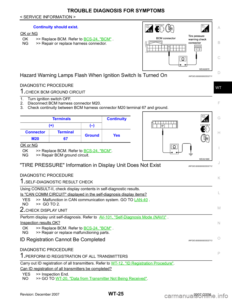
2.CHECK TIRE PRESSURE WARNING CHECK CONNECTOR CIRCUIT
Check continuity between BCM harness connector M18 terminal 15 and check connector M123 terminal 1. Terminals Voltage
(Approx.)
(+) (–)
Connector Terminal
GroundBattery
voltage
M18 38
WEIA0038E
Terminals Continuity
(+) (–)
Connector Terminal
Ground Yes
M20 67
WEIA0189E
SEIA0347E
Page 3014 of 3061
TROUBLE DIAGNOSIS FOR SYMPTOMS
WT-25
< SERVICE INFORMATION >
C
D
F
G
H
I
J
K
L
MA
B
WT
N
O
P
OK or NG
OK >> Replace BCM. Refer to BCS-24, "BCM" .
NG >> Repair or replace harness connector.
Hazard Warning Lamps Flash When Ignition Switch Is Turned OnINFOID:0000000003532711
DIAGNOSTIC PROCEDURE
1.CHECK BCM GROUND CIRCUIT
1. Turn ignition switch OFF.
2. Disconnect BCM harness connector M20.
3. Check continuity between BCM harness connector M20 terminal 67 and ground.
OK or NG
OK >> Replace BCM. Refer to BCS-24, "BCM".
NG >> Repair BCM ground circuit.
"TIRE PRESSURE" Information in Display Unit Does Not ExistINFOID:0000000003532712
DIAGNOSTIC PROCEDURE
1.SELF-DIAGNOSTIC RESULT CHECK
Using CONSULT-II, check display contents in self-diagnostic results.
Is "CAN COMM CIRCUIT" displayed in the self-diagnosis display items?
YES >> Malfunction in CAN communication system. GO TO LAN-40 .
NO >> GO TO 2.
2.CHECK DISPLAY UNIT
Perform display unit self-diagnosis. Refer to AV-101, "
Self-Diagnosis Mode (NAVI)" .
Inspection results OK?
OK >> Replace BCM. Refer to BCS-24, "BCM" .
NG >> Repair or replace malfunctioning parts.
ID Registration Cannot Be CompletedINFOID:0000000003532713
DIAGNOSTIC PROCEDURE
1.PERFORM ID REGISTRATION OF ALL TRANSMITTERS
Carry out ID registration of all transmitters. Refer to WT-12, "
ID Registration Procedure".
Can ID registration of all transmitters be completed?
YES >> Inspection End.
NO >> GO TO WT-20, "
Data from Transmitter Not Being Received". Continuity should exist.
WEIA0097E
Terminals Continuity
(+) (–)
Connector Terminal
Ground Yes
M20 67
WEIA0189E
Page 3020 of 3061
FRONT WIPER AND WASHER SYSTEM
WW-3
< SERVICE INFORMATION >
C
D
E
F
G
H
I
J
L
MA
B
WW
N
O
P
FRONT WIPER AND WASHER SYSTEM
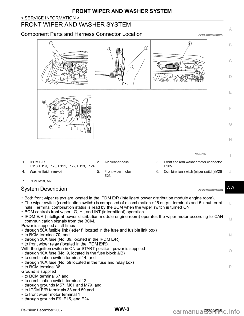
Component Parts and Harness Connector LocationINFOID:0000000003533551
System DescriptionINFOID:0000000003533552
• Both front wiper relays are located in the IPDM E/R (intelligent power distribution module engine room).
• The wiper switch (combination switch) is composed of a combination of 5 output terminals and 5 input termi-
nals. Terminal combination status is read by the BCM when the wiper switch is turned ON.
• BCM controls front wiper LO, HI, and INT (intermittent) operation.
• IPDM E/R (intelligent power distribution module engine room) operates the wiper motor according to CAN
communication signals from the BCM.
Power is supplied at all times
• through 50A fusible link (letter f, located in the fuse and fusible link box)
• to BCM terminal 70, and
• through 30A fuse (No. 39, located in the IPDM E/R)
• to front wiper relay (located in the IPDM E/R).
With the ignition switch in ON or START position, power is supplied
• through 10A fuse (No. 9, located in the fuse block J/B)
• to combination switch terminal 14, and
• through 10A fuse (No. 59 located in the fuse and relay box)
• to BCM terminal 38.
Ground is supplied
• to BCM terminal 67 and
• to combination switch terminal 12
• through grounds M57, M61 and M79, and
• to IPDM E/R terminals 38 and 59 and
• to front wiper motor terminal 1
• through grounds E9, E15, and E24.
WKIA5719E
1. IPDM E/R
E118, E119, E120, E121, E122, E123, E1242. Air cleaner case 3. Front and rear washer motor connector
E105
4. Washer fluid reservoir 5. Front wiper motor
E236. Combination switch (wiper switch) M28
7. BCM M18, M20