2007 INFINITI QX56 check oil
[x] Cancel search: check oilPage 1043 of 3061
DI-32
< SERVICE INFORMATION >
WARNING LAMPS
4WD Models
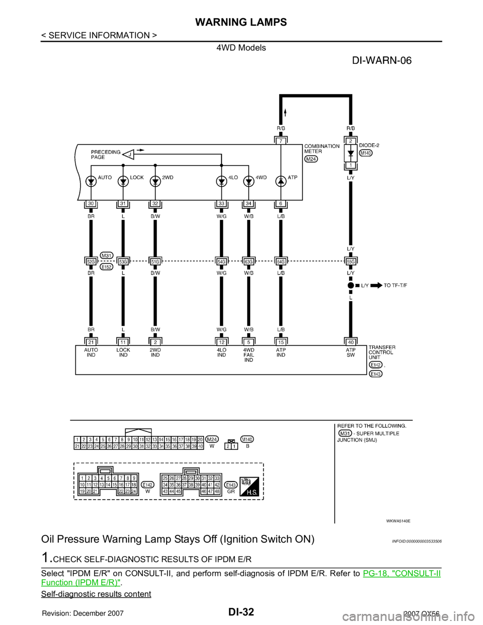
Oil Pressure Warning Lamp Stays Off (Ignition Switch ON)INFOID:0000000003533506
1.CHECK SELF-DIAGNOSTIC RESULTS OF IPDM E/R
Select "IPDM E/R" on CONSULT-II, and perform self-diagnosis of IPDM E/R. Refer to PG-18, "
CONSULT-II
Function (IPDM E/R)".
Self-diagnostic results content
WKWA5140E
Page 1044 of 3061
WARNING LAMPS
DI-33
< SERVICE INFORMATION >
C
D
E
F
G
H
I
J
L
MA
B
DI
N
O
P
No malfunction detected>>GO TO 2.
Malfunction detected>>GO TO PG-18, "
CONSULT-II Function (IPDM E/R)".
2.CHECK IPDM E/R INPUT SIGNAL
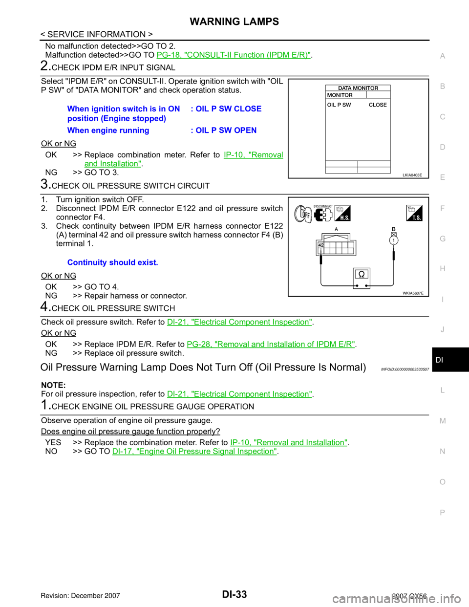
Select "IPDM E/R" on CONSULT-II. Operate ignition switch with "OIL
P SW" of "DATA MONITOR" and check operation status.
OK or NG
OK >> Replace combination meter. Refer to IP-10, "Removal
and Installation".
NG >> GO TO 3.
3.CHECK OIL PRESSURE SWITCH CIRCUIT
1. Turn ignition switch OFF.
2. Disconnect IPDM E/R connector E122 and oil pressure switch
connector F4.
3. Check continuity between IPDM E/R harness connector E122
(A) terminal 42 and oil pressure switch harness connector F4 (B)
terminal 1.
OK or NG
OK >> GO TO 4.
NG >> Repair harness or connector.
4.CHECK OIL PRESSURE SWITCH
Check oil pressure switch. Refer to DI-21, "
Electrical Component Inspection".
OK or NG
OK >> Replace IPDM E/R. Refer to PG-28, "Removal and Installation of IPDM E/R".
NG >> Replace oil pressure switch.
Oil Pressure Warning Lamp Does Not Turn Off (Oil Pressure Is Normal)INFOID:0000000003533507
NOTE:
For oil pressure inspection, refer to DI-21, "
Electrical Component Inspection".
1.CHECK ENGINE OIL PRESSURE GAUGE OPERATION
Observe operation of engine oil pressure gauge.
Does engine oil pressure gauge function properly?
YES >> Replace the combination meter. Refer to IP-10, "Removal and Installation".
NO >> GO TO DI-17, "
Engine Oil Pressure Signal Inspection". When ignition switch is in ON
position (Engine stopped): OIL P SW CLOSE
When engine running : OIL P SW OPEN
LKIA0403E
Continuity should exist.
WKIA5607E
Page 1159 of 3061
EC-76
< SERVICE INFORMATION >
BASIC SERVICE PROCEDURE
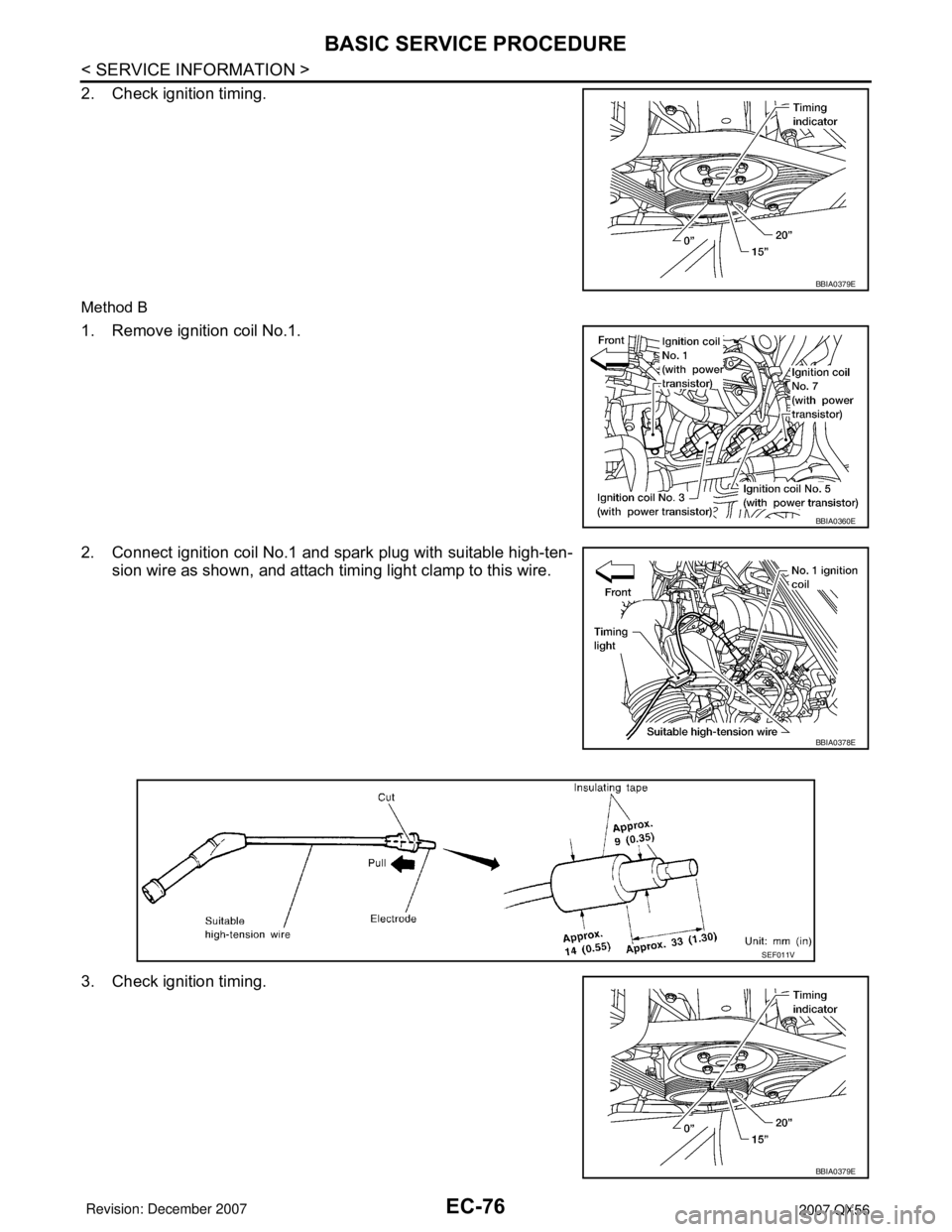
2. Check ignition timing.
Method B
1. Remove ignition coil No.1.
2. Connect ignition coil No.1 and spark plug with suitable high-ten-
sion wire as shown, and attach timing light clamp to this wire.
3. Check ignition timing.
BBIA0379E
BBIA0360E
BBIA0378E
SEF011V
BBIA0379E
Page 1203 of 3061

EC-120
< SERVICE INFORMATION >
TROUBLE DIAGNOSIS
*: Leaving cooling fan OFF with CONSULT-II while engine is running may cause the engine to overheat.
DTC & SRT CONFIRMATION MODE
SRT STATUS Mode
For details, refer to EC-49, "Emission-related Diagnostic Information".
SRT WORK SUPPORT Mode
This mode enables a technician to drive a vehicle to set the SRT while monitoring the SRT status.
DTC WORK SUPPORT Mode
TEST ITEM CONDITION JUDGEMENT CHECK ITEM (REMEDY)
FUEL INJEC-
TION• Engine: Return to the original
trouble condition
• Change the amount of fuel injec-
tion using CONSULT-II.If trouble symptom disappears, see
CHECK ITEM.• Harness and connectors
• Fuel injector
• Air fuel ratio (A/F) sensor 1
IGNITION TIM-
ING• Engine: Return to the original
trouble condition
• Timing light: Set
• Retard the ignition timing using
CONSULT-II.If trouble symptom disappears, see
CHECK ITEM.• Perform Idle Air Volume Learning.
POWER BAL-
ANCE• Engine: After warming up, idle the
engine.
• A/C switch: OFF
• Selector lever: P or N
• Cut off each injector signal one at
a time using CONSULT-II.Engine runs rough or dies.• Harness and connectors
• Compression
• Fuel injector
• Power transistor
•Spark plug
• Ignition coil
COOLING FAN*• Ignition switch: ON
• Turn the cooling fan HI and OFF
using CONSULT-II.Cooling fan moves and stops.• Harness and connectors
• Cooling fan motor
• IPDM E/R
ENG COOLANT
TEMP• Engine: Return to the original
trouble condition
• Change the engine coolant tem-
perature using CONSULT-II.If trouble symptom disappears, see
CHECK ITEM.• Harness and connectors
• Engine coolant temperature sen-
sor
• Fuel injector
FUEL PUMP RE-
LAY• Ignition switch: ON
(Engine stopped)
• Turn the fuel pump relay ON and
OFF using CONSULT-II and lis-
ten to operating sound.Fuel pump relay makes the operat-
ing sound.• Harness and connectors
•Fuel pump relay
PURG VOL
CONT/V• Engine: After warming up, run en-
gine at 1,500 rpm.
• Change the EVAP canister purge
volume control solenoid valve
opening percent using CON-
SULT-II.Engine speed changes according to
the opening percent.• Harness and connectors
• Solenoid valve
FUEL/T TEMP
SEN• Change the fuel tank temperature using CONSULT-II.
VENT CON-
TROL/V• Ignition switch: ON
(Engine stopped)
• Turn solenoid valve ON and OFF
with the CONSULT-II and listen to
operating sound.Solenoid valve makes an operating
sound.• Harness and connectors
• Solenoid valve
V/T ASSIGN AN-
GLE• Engine: Return to the original
trouble condition
• Change intake valve timing using
CONSULT-II.If trouble symptom disappears, see
CHECK ITEM.• Harness and connectors
• Intake valve timing control sole-
noid valve
ALTERNATOR
DUTY•Engine: Idle
• Change duty ratio using CON-
SULT-II.Battery voltage changes.• Harness and connectors
• IPDM E/R
•Alternator
Page 1215 of 3061
EC-132
< SERVICE INFORMATION >
TROUBLE DIAGNOSIS - SPECIFICATION VALUE
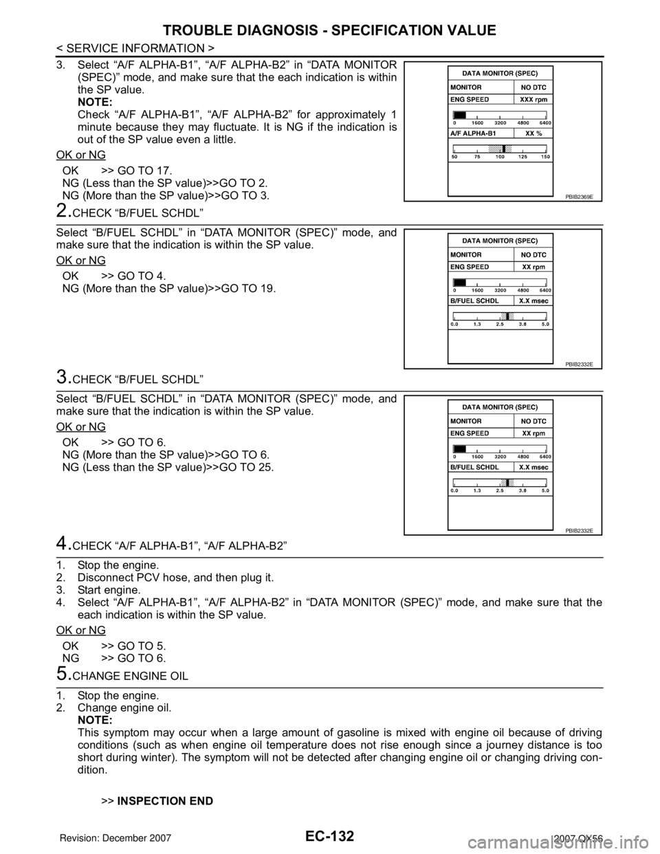
3. Select “A/F ALPHA-B1”, “A/F ALPHA-B2” in “DATA MONITOR
(SPEC)” mode, and make sure that the each indication is within
the SP value.
NOTE:
Check “A/F ALPHA-B1”, “A/F ALPHA-B2” for approximately 1
minute because they may fluctuate. It is NG if the indication is
out of the SP value even a little.
OK or NG
OK >> GO TO 17.
NG (Less than the SP value)>>GO TO 2.
NG (More than the SP value)>>GO TO 3.
2.CHECK “B/FUEL SCHDL”
Select “B/FUEL SCHDL” in “DATA MONITOR (SPEC)” mode, and
make sure that the indication is within the SP value.
OK or NG
OK >> GO TO 4.
NG (More than the SP value)>>GO TO 19.
3.CHECK “B/FUEL SCHDL”
Select “B/FUEL SCHDL” in “DATA MONITOR (SPEC)” mode, and
make sure that the indication is within the SP value.
OK or NG
OK >> GO TO 6.
NG (More than the SP value)>>GO TO 6.
NG (Less than the SP value)>>GO TO 25.
4.CHECK “A/F ALPHA-B1”, “A/F ALPHA-B2”
1. Stop the engine.
2. Disconnect PCV hose, and then plug it.
3. Start engine.
4. Select “A/F ALPHA-B1”, “A/F ALPHA-B2” in “DATA MONITOR (SPEC)” mode, and make sure that the
each indication is within the SP value.
OK or NG
OK >> GO TO 5.
NG >> GO TO 6.
5.CHANGE ENGINE OIL
1. Stop the engine.
2. Change engine oil.
NOTE:
This symptom may occur when a large amount of gasoline is mixed with engine oil because of driving
conditions (such as when engine oil temperature does not rise enough since a journey distance is too
short during winter). The symptom will not be detected after changing engine oil or changing driving con-
dition.
>>INSPECTION END
PBIB2369E
PBIB2332E
PBIB2332E
Page 1216 of 3061
TROUBLE DIAGNOSIS - SPECIFICATION VALUE
EC-133
< SERVICE INFORMATION >
C
D
E
F
G
H
I
J
K
L
MA
EC
N
P O
6.CHECK FUEL PRESSURE
Check fuel pressure. (Refer to EC-80, "
Fuel Pressure Check" .)
OK or NG
OK >> GO TO 9.
NG (Fuel pressure is too high)>>Replace fuel pressure regulator, refer to EC-80, "
Fuel Pressure Check" .
GO TO 8.
NG (Fuel pressure is too low)>>GO TO 7.
7.DETECT MALFUNCTIONING PART
1. Check the following.
- Clogged and bent fuel hose and fuel tube
- Clogged fuel filter
- Fuel pump and its circuit (Refer to EC-613
.)
2. If NG, repair or replace the malfunctioning part. (Refer to EC-80, "
Fuel Pressure Check" .)
If OK, replace fuel pressure regulator.
>> GO TO 8.
8.CHECK “A/F ALPHA-B1”, “A/F ALPHA-B2”
1. Start engine.
2. Select “A/F ALPHA-B1”, “A/F ALPHA-B2” in “DATA MONITOR (SPEC)” mode, and make sure that the
each indication is within the SP value.
OK or NG
OK >>INSPECTION END
NG >> GO TO 9.
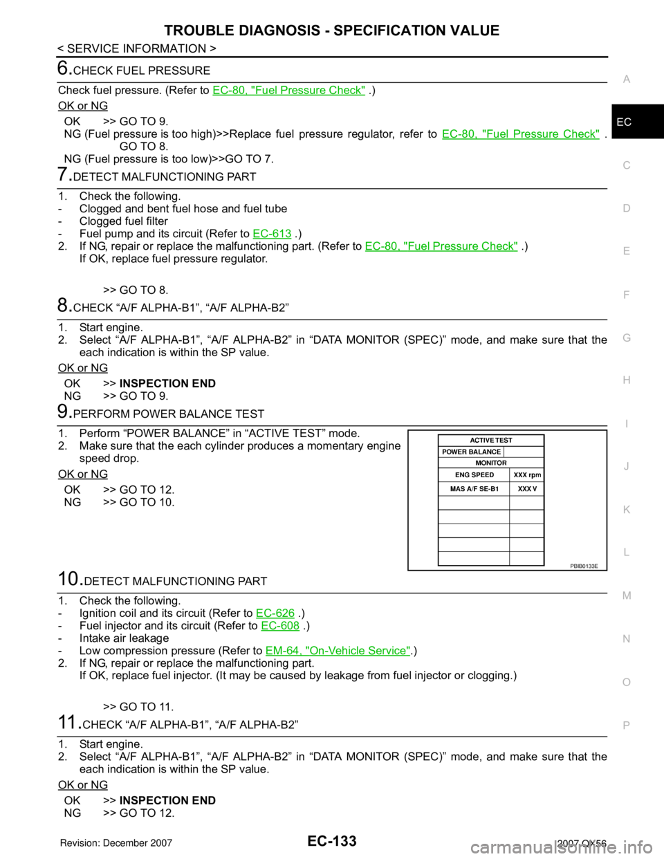
9.PERFORM POWER BALANCE TEST
1. Perform “POWER BALANCE” in “ACTIVE TEST” mode.
2. Make sure that the each cylinder produces a momentary engine
speed drop.
OK or NG
OK >> GO TO 12.
NG >> GO TO 10.
10.DETECT MALFUNCTIONING PART
1. Check the following.
- Ignition coil and its circuit (Refer to EC-626
.)
- Fuel injector and its circuit (Refer to EC-608
.)
- Intake air leakage
- Low compression pressure (Refer to EM-64, "
On-Vehicle Service".)
2. If NG, repair or replace the malfunctioning part.
If OK, replace fuel injector. (It may be caused by leakage from fuel injector or clogging.)
>> GO TO 11.
11 .CHECK “A/F ALPHA-B1”, “A/F ALPHA-B2”
1. Start engine.
2. Select “A/F ALPHA-B1”, “A/F ALPHA-B2” in “DATA MONITOR (SPEC)” mode, and make sure that the
each indication is within the SP value.
OK or NG
OK >>INSPECTION END
NG >> GO TO 12.
PBIB0133E
Page 1217 of 3061
EC-134
< SERVICE INFORMATION >
TROUBLE DIAGNOSIS - SPECIFICATION VALUE
12.CHECK A/F SENSOR 1 FUNCTION
Perform all DTC Confirmation Procedure related with A/F sensor 1.
• For DTC P0130, P0150, refer to EC-225, "
DTC Confirmation Procedure" .
• For DTC P0131, P0151, refer to EC-234, "
DTC Confirmation Procedure" .
• For DTC P0132, P0132, refer to EC-242, "
DTC Confirmation Procedure" .
• For DTC P0133, P0153, refer to EC-250, "
DTC Confirmation Procedure" .
• For DTC P2A00, P2A03, refer to EC-588, "
DTC Confirmation Procedure" .
OK or NG
OK >> GO TO 15.
NG >> GO TO 13.
13.CHECK A/F SENSOR 1 CIRCUIT
Perform Diagnostic Procedure according to corresponding DTC.
>> GO TO 14.
14.CHECK “A/F ALPHA-B1”, “A/F ALPHA-B2”
1. Start engine.
2. Select “A/F ALPHA-B1”, “A/F ALPHA-B2” in “DATA MONITOR (SPEC)” mode, and make sure that the
each indication is within the SP value.
OK or NG
OK >>INSPECTION END
NG >> GO TO 15.
15.DISCONNECT AND RECONNECT ECM HARNESS CONNECTOR
1. Stop the engine.
2. Disconnect ECM harness connector. Check pin terminal and connector for damage, and then reconnect it.
>> GO TO 16.
16.CHECK “A/F ALPHA-B1”, “A/F ALPHA-B2”
1. Start engine.
2. Select “A/F ALPHA-B1”, “A/F ALPHA-B2” in “DATA MONITOR (SPEC)” mode, and make sure that the
each indication is within the SP value.
OK or NG
OK >>INSPECTION END
NG >> Detect malfunctioning part according to EC-90, "
Symptom Matrix Chart" .
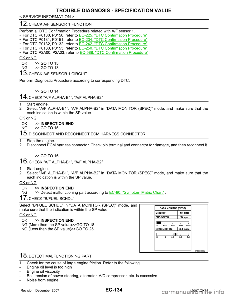
17.CHECK “B/FUEL SCHDL”
Select “B/FUEL SCHDL” in “DATA MONITOR (SPEC)” mode, and
make sure that the indication is within the SP value.
OK or NG
OK >>INSPECTION END
NG (More than the SP value)>>GO TO 18.
NG (Less than the SP value)>>GO TO 25.
18.DETECT MALFUNCTIONING PART
1. Check for the cause of large engine friction. Refer to the following.
- Engine oil level is too high
- Engine oil viscosity
- Belt tension of power steering, alternator, A/C compressor, etc. is excessive
- Noise from engine
PBIB2332E
Page 1219 of 3061
EC-136
< SERVICE INFORMATION >
TROUBLE DIAGNOSIS - SPECIFICATION VALUE
3. Perform EC-77, "VIN Registration" .
4. Perform EC-77, "
Accelerator Pedal Released Position Learning" .
5. Perform EC-77, "
Throttle Valve Closed Position Learning" .
6. Perform EC-78, "
Idle Air Volume Learning" .
>> GO TO 29.
25.CHECK INTAKE SYSTEM
Check for the cause of uneven air flow through mass air flow sensor. Refer to the following.
• Crushed air ducts
• Malfunctioning seal of air cleaner element
• Uneven dirt of air cleaner element
• Improper specification of intake air system
OK or NG
OK >> GO TO 27.
NG >> Repair or replace malfunctioning part, and then GO TO 26.
26.CHECK “B/FUEL SCHDL”
Select “B/FUEL SCHDL” in “DATA MONITOR (SPEC)” mode, and make sure that the indication is within the
SP value.
OK or NG
OK >>INSPECTION END
NG (Less than the SP value)>>GO TO 27.
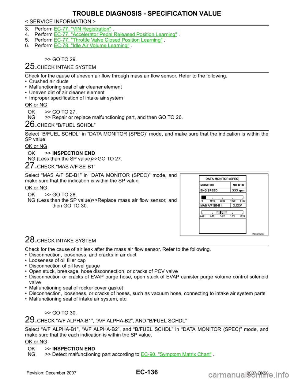
27.CHECK “MAS A/F SE-B1”
Select “MAS A/F SE-B1” in “DATA MONITOR (SPEC)” mode, and
make sure that the indication is within the SP value.
OK or NG
OK >> GO TO 28.
NG (Less than the SP value)>>Replace mass air flow sensor, and
then GO TO 30.
28.CHECK INTAKE SYSTEM
Check for the cause of air leak after the mass air flow sensor. Refer to the following.
• Disconnection, looseness, and cracks in air duct
• Looseness of oil filler cap
• Disconnection of oil level gauge
• Open stuck, breakage, hose disconnection, or cracks of PCV valve
• Disconnection or cracks of EVAP purge hose, open stuck of EVAP canister purge volume control solenoid
valve
• Malfunctioning seal of rocker cover gasket
• Disconnection, looseness, or cracks of hoses, such as vacuum hose, connecting to intake air system parts
• Malfunctioning seal of intake air system, etc.
>> GO TO 30.
29.CHECK “A/F ALPHA-B1”, “A/F ALPHA-B2”, AND “B/FUEL SCHDL”
Select “A/F ALPHA-B1”, “A/F ALPHA-B2”, and “B/FUEL SCHDL” in “DATA MONITOR (SPEC)” mode, and
make sure that the each indication is within the SP value.
OK or NG
OK >>INSPECTION END
NG >> Detect malfunctioning part according to EC-90, "
Symptom Matrix Chart" .
PBIB2370E