Page 4023 of 4647
PS-42
HYDRAULIC LINE
Revision: 2007 April2007 M35/M45
Refer to GI-11, "Components" , and the followings for the symbols in the figure.
: Apply power steering fluid.
Page 4025 of 4647
PS-44
HYDRAULIC LINE
Revision: 2007 April2007 M35/M45
Removal and InstallationNGS000DL
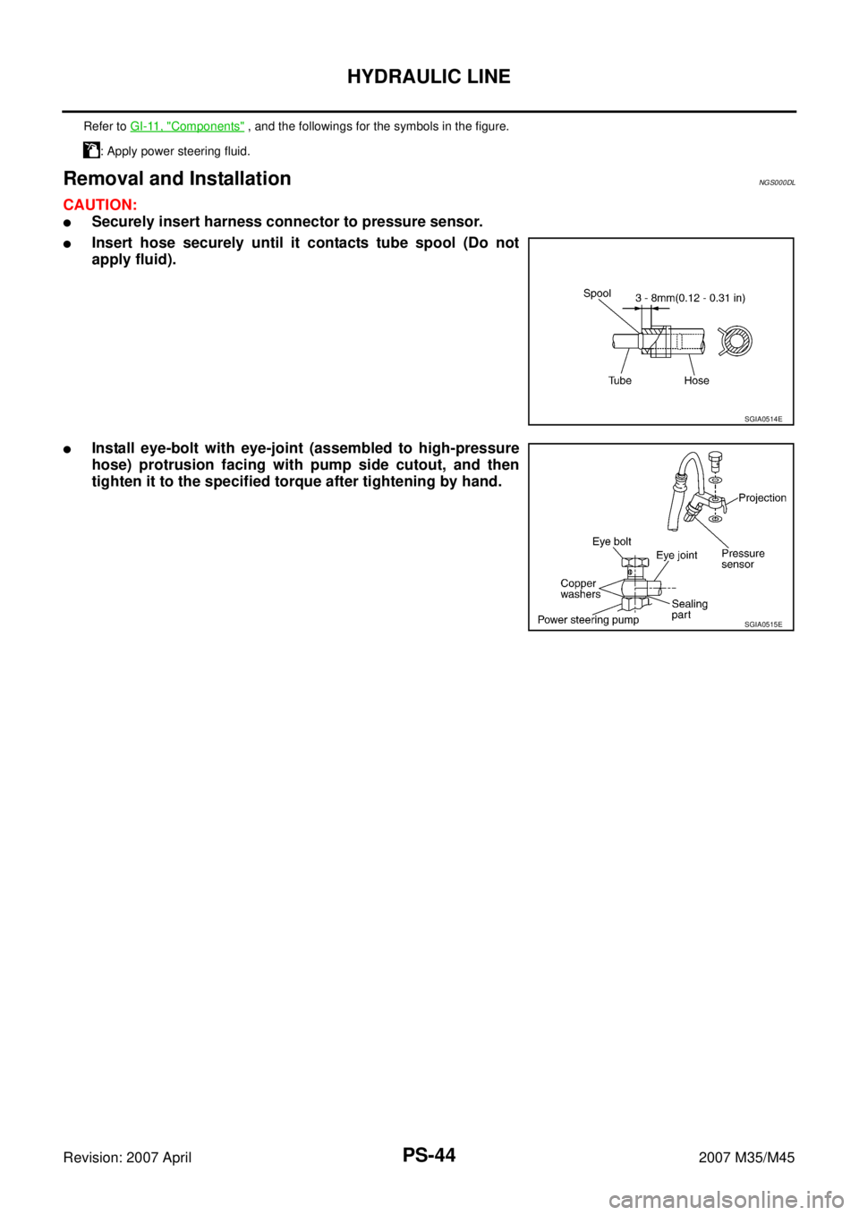
CAUTION:
�Securely insert harness connector to pressure sensor.
�Insert hose securely until it contacts tube spool (Do not
apply fluid).
�Install eye-bolt with eye-joint (assembled to high-pressure
hose) protrusion facing with pump side cutout, and then
tighten it to the specified torque after tightening by hand.
Refer to GI-11, "Components" , and the followings for the symbols in the figure.
: Apply power steering fluid.
SGIA0514E
SGIA0515E
Page 4032 of 4647
 of each component")
WHEEL HUB
RAX-5
C
E
F
G
H
I
J
K
L
MA
B
RAX
Revision: 2007 April2007 M35/M45
WHEEL HUBPFP:43202
On-Vehicle Inspection NDS000FQ
Make sure the mounting conditions (looseness, back lash) of each component and component conditions
(wear, damage) are normal.
WHEEL BEARING INSPECTION
�Move wheel hub and bearing assembly in the axial direction by hand. Make sure there is no looseness of
wheel bearing.
�Rotate wheel hub, and make sure that is no unusual noise or other irregular conditions. If there is any of
irregular conditions, replace wheel hub and bearing assembly.
Removal and InstallationNDS000FR
COMPONENT
REMOVAL
Wheel Hub and Bearing Assembly
1. Remove tires from vehicle with a power tool.
2. Remove rear brake caliper with a power tool. Hang it in a place where it will not interfere with work. Refer
to BR-30, "
Removal and Installation of Brake Caliper Assembly" .
CAUTION:
Do not depress brake pedal while brake caliper is removed.
3. Put matching mark on disc rotor and the wheel hub and bearing
assembly then removing disc rotor.
4. Remove cotter pin, then loosen hub lock nut with a power tool.Axial end play : 0.05 mm (0.002 in) or less
1. Axle housing 2. Ball seat 3. Bushing
4. Back plate 5. Anchor block 6. Wheel hub and bearing assembly
7. Cotter pin
Refer to GI-11, "
Components" , for the symbols in the figure.
SDIA3251E
SDIA2638E
Page 4035 of 4647

RAX-8
REAR DRIVE SHAFT
Revision: 2007 April2007 M35/M45
REAR DRIVE SHAFTPFP:39600
Removal and InstallationNDS000FS
COMPONENT
VQ35DE model
VK45DE model
REMOVAL
1. Remove tires from vehicle with a power tool.
2. Remove cotter pin, then loosen hub lock nut with a power tool.
3. Remove stabilizer connecting rod mounting bracket fixing bolt and free stabilizer connecting rod. Refer to
RSU-7, "
Components" .
4. Separate the wheel hub and bearing assembly from drive shaft
by lightly tapping the end with a suitable tool hammer and wood
block, and then remove hub lock nut.
CAUTION:
�Do not place drive shaft joint at an extreme angle. Also be
careful not to overextend slide joint.
�Do not allow drive shaft to hang down without support for
counterpart such as joint sub-assembly, and other parts.
NOTE:
Using a puller (suitable tool) if the wheel hub and bearing
assembly and drive shaft cannot be separated even after per-
forming the above procedure.
5. Remove mounting bolts between side flange and drive shaft with a power tool.
INSPECTION AFTER REMOVAL
�Move joint up/down, left/right, and in the axial direction. Check for any rough movement or significant
looseness.
SDIA3294E
1. Side flange 2. Drive shaft 3. Cotter pin
Refer to GI-11, "
Components" , for the symbols in the figure.
SDIA3248E
1. Side flange 2. Drive shaft 3. Cotter pin
Refer to GI-11, "
Components" , for the symbols in the figure.
SDIA1821E
Page 4036 of 4647

REAR DRIVE SHAFT
RAX-9
C
E
F
G
H
I
J
K
L
MA
B
RAX
Revision: 2007 April2007 M35/M45
�Check boot for cracks or other damage, and also for grease
leakage.
�If a malfunction is found, disassemble drive shaft, and then
replace with new one.
INSTALLATION
Installation is the reverse order of removal. For tightening torque. Refer to RAX-8, "COMPONENT" .
CAUTION:
Do not reuse non-reusable parts.
Disassembly and AssemblyNDS000FT
COMPONENT
DISASSEMBLY
Final Drive Side
1. Place shaft in a vise.
CAUTION:
When retaining shaft in a vise, always use copper or aluminum plates between vise and shaft.
2. Remove boot bands, and then remove boot from housing.
3. If plug needs to be removed, move boot to wheel side, and take it out with a plastic hammer.
4. Put matching marks on housing and shaft.
CAUTION:
Use paint or similar substance for matching marks. Do not scratch the surface.
RAA0030D
1. Plug 2. Housing 3. Snap ring
4. Ball cage, steel ball and Inner race
assembly5. Stopper ring 6. Boot band
7. Boot 8. Shaft 9. Circular clip
10. Joint sub-assembly 11. Dust shield
Refer to GI-11, "
Components" and the followings for symbols in the figure.
: NISSAN genuine grease or equivalent
SDIA3029J
Page 4085 of 4647
RFD-16
REAR FINAL DRIVE ASSEMBLY
Revision: 2007 April2007 M35/M45
REAR FINAL DRIVE ASSEMBLYPFP:38300
Removal and InstallationNDS000F7
COMPONENTS
REMOVAL
1. Remove center muffler with a power tool. Refer to EX-3, "EXHAUST SYSTEM" .
2. Remove rear stabilizer bar with a power tool. Refer to RSU-17, "
STABILIZER BAR" .
3. Remove propeller shaft from the final drive. Refer to PR-8, "
Removal and Installation" .
4. Remove drive shaft from final drive with a power tool. Then sus-
pend it by wire etc. Refer to RAX-8, "
REAR DRIVE SHAFT" .
5. Remove breather hose from the final drive.
6. Remove rear wheel sensor. Refer to BRC-54, "
WHEEL SEN-
SOR" .
1. Rear final drive assembly 2. Upper stopper 3. Propeller shaft
4. Washer 5. Lower stopper 6. Drive shaft
A: For VQ35DE models
B: For VK45DE models
Refer to GI-11, "
Components" , for the symbols in the figure.
PDIA0967E
SDIA1094E
Page 4087 of 4647

RFD-18
REAR FINAL DRIVE ASSEMBLY
Revision: 2007 April2007 M35/M45
Disassembly and AssemblyNDS000F8
COMPONENTS
1. Drive pinion lock nut 2. Companion flange 3. Front oil seal
4. Pinion front bearing 5. Gear carrier 6. Side oil seal
7. Side flange 8. Collapsible spacer 9. Pinion rear bearing
10. Pinion height adjusting washer 11. Drive pinion 12. Side bearing adjusting washer
13. Side bearing 14. Side gear thrust washer 15. Circular clip
16. Side gear 17. Lock pin 18. Pinion mate gear
19. Pinion mate thrust washer 20. Pinion mate shaft 21. Drive gear
22. Differential case 23. Bearing cap 24. Filler plug
25. Gasket 26. Rear cover 27. Drain plug
A: Oil seal lip
B: Screw hole
C: After tightening the bolts to the specified torque, tighten the bolts additionally by turning the bolts 31 to 36 degrees.
Refer to GI-11, "
Components" and the followings for the symbols in the figure.
:Apply gear oil.
:Apply anti-corrosion oil.
:Apply Genuine Silicone RTV or equivalent. Refer to GI-47, "
Recommended Chemical Products and Sealants" .
:Apply Genuine High Strength Thread Locking Sealant or equivalent. Refer to GI-47, "
Recommended Chemical Prod-
ucts and Sealants" .
PDIA0986E
Page 4115 of 4647

RSU-8
REAR SUSPENSION ASSEMBLY
Revision: 2007 April2007 M35/M45
Removal and InstallationNES000J9
REMOVAL
1. Remove tires with a power tool.
2. Remove brake caliper with a power tool. Hang it in a place where it will not interfere with work. Refer to
BR-28, "
REAR DISC BRAKE" .
CAUTION:
Do not depressing brake pedal while brake caliper is removed.
3. Put matching marks on both disc rotor and the wheel hub and
bearing assembly, then remove disc rotor.
4. Remove rear under cover.
5. Remove wheel sensor from rear final drive.
6. Remove harness from rear final drive and rear suspension
member.
7. Remove center muffler. Refer to EX-3, "
EXHAUST SYSTEM" .
8. Remove rear propeller shaft. Refer to PR-6, "
REAR PROPEL-
LER SHAFT" .
9. Remove stabilizer bar. Refer to RSU-17, "
STABILIZER BAR" .
10. Remove parking brake cable mounting bolt and separate park-
ing brake cable from vehicle and rear suspension member. Refer to PB-4, "
PARKING BRAKE CONTROL"
.
11. Remove rear lower link and coil spring. Refer to RSU-16, "
REAR LOWER LINK & COIL SPRING" .
12. Remove mounting bolt on lower side of shock absorber. Refer to RSU-10, "
SHOCK ABSORBER" .
13. Set jack under rear final drive.
14. Remove member stay from vehicle.
15. Remove rear pin stay mounting bolts and nuts.
16. Gradually lowering jack, remove rear pin stay and rear suspension assembly.
INSTALLATION
�Installation is the reverse order of the removal. For tightening torque, refer to RSU-7, "Components" .
CAUTION:
Do not reuse non-reusable parts.
�Assemble disc rotor and wheel hub and bearing assembly by
aligning each matching mark as shown in the figure when install-
ing disc rotor.
�Perform the final tightening of each of parts under unladen con-
ditions, which were removed when removing rear suspension
assembly. Check the wheel alignment. Refer to RSU-5, "
Wheel
Alignment Inspection" .
�Adjust neutral position of steering angle sensor after checking
the wheel alignment. Refer to BRC-6, "
Adjustment of Steering
Angle Sensor Neutral Position" .
�Check for the following after finishing work.
1. Washer 2. Mounting seal 3. Bushing (upper side)
4. Distance tube 5. Mounting bracket 6. Bushing (lower side)
7. Bound bumper cover 8. Bound bumper 9. Shock absorber
10. Axle assembly 11. Upper seat 12. Coil spring
13. Ball seat 14. Rubber seat 15. Cotter pin
16. Suspension arm 17. Connecting rod mounting bracket 18. Connecting rod
19. Mount stopper 20. Rear lower link 21. Front lower link
22. Radius rod 23. Stabilizer Bushing 24. Stabilizer Clamp
25. Stabilizer bar 26. Rear suspension member 27. Member stay
28. Stopper rubber 29. Cap 30. Rear pin stay
Refer to GI-11, "
Components" , for to the symbols in the figure.
SDIA2638E
SDIA2638E