Page 3975 of 4647

Removal and InstallationNDS000EF
REMOVAL
1. Move the A/T select lever to N position and release the par")
PR-8
REAR PROPELLER SHAFT
Revision: 2007 April2007 M35/M45
VQ35DE AWD MODELS (3F80A-1VL107 TYPE)
Removal and InstallationNDS000EF
REMOVAL
1. Move the A/T select lever to N position and release the parking brake.
2. Remove the floor reinforcement.
3. Remove the center muffler with power tool. Refer to EX-3, "
EXHAUST SYSTEM" .
4.For VQ35DE 2WD models
�Put matching marks on propeller shaft rebro joint with final
drive companion flange.
CAUTION:
For matching marks, use paint. Do not damage propeller
shaft rebro joint and companion flange.
For VK45DE 2WD models
�Put matching marks on propeller shaft rubber coupling with
transmission companion flange and on rebro joint with final
drive companion flange.
CAUTION:
For matching marks, use paint. Do not damage rubber coupling, rebro joint and companion
flanges.
For VQ35DE AWD models
�Put matching marks on propeller shaft flange yoke with transfer companion flange and on rebro joint
with final drive companion flange.
CAUTION:
For matching marks, use paint. Do not damage propeller shaft flange yoke, rebro joint and com-
panion flanges.
PDIA0966E
1. Propeller shaft (1st shaft) 2. Center flange 3. Center bearing mounting bracket
(Lower)
4. Floor reinforcement 5. Center bearing assembly 6. Propeller shaft (2nd shaft)
7. Clip 8. Center bearing mounting bracket
(Upper)9. Washer
10. Lock nut
A: Both side
B: For the tightening torque, refer to PR-12, "
ASSEMBLY" .
Refer to GI-11, "
Components" , for the symbols in the figure.
PDIA0470E
Page 3994 of 4647
STEERING COLUMN
PS-13
C
D
E
F
H
I
J
K
L
MA
B
PS
Revision: 2007 April2007 M35/M45
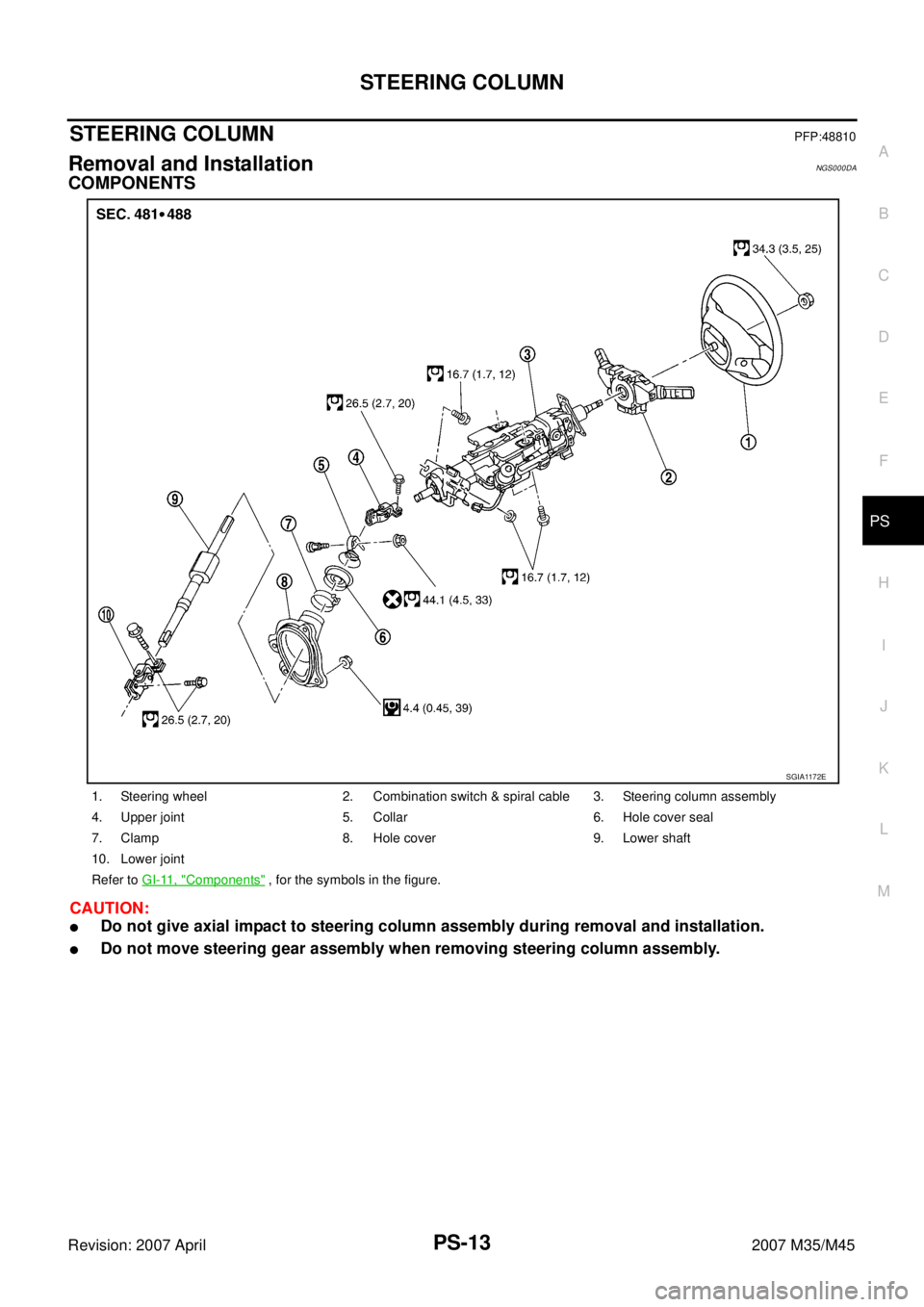
STEERING COLUMNPFP:48810
Removal and InstallationNGS000DA
COMPONENTS
CAUTION:
�Do not give axial impact to steering column assembly during removal and installation.
�Do not move steering gear assembly when removing steering column assembly.
1. Steering wheel 2. Combination switch & spiral cable 3. Steering column assembly
4. Upper joint 5. Collar 6. Hole cover seal
7. Clamp 8. Hole cover 9. Lower shaft
10. Lower joint
Refer to GI-11, "
Components" , for the symbols in the figure.
SGIA1172E
Page 3998 of 4647

STEERING COLUMN
PS-17
C
D
E
F
H
I
J
K
L
MA
B
PS
Revision: 2007 April2007 M35/M45
Disassembly and AssemblyNGS000DB
COMPONENTS
DISASSEMBLY
1. Remove fixing screws of telescopic sensor, and then remove telescopic sensor from steering column.
2. Remove fixing screw of bracket, and then remove bracket from telescopic motor.
3. Remove fixing bolt of telescopic motor, and then remove telescopic motor from steering column.
4. Remove fixing screws of tilt sensor, and then remove tilt sensor from steering column.
5. Remove fixing bolt of tilt motor, and then remove tilt motor from steering column.
6. Remove fixing screws of brackets, and then remove brackets from steering column.
INSPECTION AFTER DISASSEMBLY
Check component parts for damage or other malfunctions. Replace if there are.
ASSEMBLY
Assembly is the reverse order of disassembly. For tightening torque, refer to PS-17, "COMPONENTS" .
1. Bracket 2. Bracket 3. Steering column
4. Telescopic motor 5. Bracket 6. Telescopic sensor
7. Tilt sensor 8. Tilt motor 9. Bracket
10. Bracket
Refer to GI-11, "
Components" , for the symbols in the figure.
SGIA1634E
Page 4000 of 4647

POWER STEERING GEAR AND LINKAGE
PS-19
C
D
E
F
H
I
J
K
L
MA
B
PS
Revision: 2007 April2007 M35/M45
POWER STEERING GEAR AND LINKAGEPFP:49001
Removal and InstallationNGS000DC
COMPONENTS
CAUTION:
Spiral cable may be cut if steering wheel turns while separating steering column assembly and steer-
ing gear assembly. Be sure to secure steering wheel using string to avoid turning.
REMOVAL
1. Set vehicle to the straight-ahead position.
2. Remove tires from vehicle with a power tool.
3. Remove undercover from vehicle with a power tool.
4. Remove lower side fixing bolt of lower joint.
5. Remove cotter pin (1), and then loosen the nut.
6. Remove steering outer socket (2) from steering knuckle (3) so
as not to damage ball joint boot (4) using the ball joint remover
(suitable tool).
CAUTION:
Temporarily tighten the nut to prevent damage to threads
and to prevent the ball joint remover from suddenly coming
off.
7. Remove high and low pressure piping of hydraulic piping, and
then drain power steering fluid. Refer to PS-39, "
HYDRAULIC
LINE" .
1. Cotter pin 2. Steering gear assembly 3. Steering gear assembly
(AWD models)
Refer to GI-11, "
Components" , for the symbols in the figure.
SGIA1387E
SGIA0844E
SGIA1183E
Page 4002 of 4647

POWER STEERING GEAR AND LINKAGE
PS-21
C
D
E
F
H
I
J
K
L
MA
B
PS
Revision: 2007 April2007 M35/M45
Disassembly and AssemblyNGS000DD
COMPONENTS
CAUTION:
�Disassemble and assemble steering gear assembly by securing the mounting area in a vise using
copper plates.
�Clean steering gear assembly with kerosene before disassembling. Be careful to avoid splashing
or applying any kerosene over connector of discharge port or return port.
1. Outer socket 2. Boot clamp 3. Boot
4. Inner socket 5. Boot clamp (stainless wire) 6. End cover assembly
7. Rack oil seal 8. Rack Teflon ring 9. O-ring
10. Rack assembly 11. Gear housing assembly 12. Cylinder tubes
13. O-ring 14. Gear-sub assembly 15. power steering solenoid valve
16. Rear cover cap
Refer to GI-11, "
Components" , and the followings for the symbols in the figure.
: Apply power steering fluid.
: A p p l y G e n u i n e L i q u i d G a s k e t , T h r e e B o n d 1111 B o r e q u i v a l e n t .
: Apply multi-purpose grease.
SGIA1388E
Page 4012 of 4647
POWER STEERING OIL PUMP
PS-31
C
D
E
F
H
I
J
K
L
MA
B
PS
Revision: 2007 April2007 M35/M45
Disassembly and Assembly (Models with VK45DE)NGS000DG
COMPONENTS
INSPECTION BEFORE DISASSEMBLY
Disassemble oil pump only when the following malfunctions occur.
�If oil leakage is found on oil pump.
�Oil pump pulley is damaged or deformed.
�Performance of oil pump is low.
1. Pulley 2. Snap ring 3. Drive shaft
4. Joint 5. O-ring 6. Connector bolt
7. Flow control valve 8. Spring 9. Oil seal
10. Suction pipe 11. O-ring 12. Body assembly
13. O-ring 14. Side plate 15. Vane
16. Rotor 17. Cam ring 18. Cartridge
19. Dowel pin 20. Gasket 21. Rear cover
22. Copper washer
Refer to GI-11, "
Components" , and the followings for the symbols in the figure.
: Apply power steering fluid.
: Apply multi-purpose grease.
SGIA1187E
Page 4016 of 4647
POWER STEERING OIL PUMP
PS-35
C
D
E
F
H
I
J
K
L
MA
B
PS
Revision: 2007 April2007 M35/M45
Disassembly and Assembly (Models with VQ35DE)NGS000DH
COMPONENTS
INSPECTION BEFORE DISASSEMBLY
Disassemble oil pump only when the following malfunctions occur.
�If oil leakage is found on oil pump.
�Oil pump pulley is damaged or deformed.
�Performance of oil pump is low.
1. Pulley 2. Oil seal 3. Bracket
4. Body assembly 5. Suction pipe 6. O-ring
7. Flow control valve B assembly 8. Flow control valve spring 9. Flow control valve A
10. Dowel pin 11. Front side plate 12. Vane
13. Rotor 14. Rotor snap ring 15. Cam ring
16. Rear side plate 17. O-ring 18. Teflon ring
19. O-ring 20. Rear cover 21. Cartridge
Refer to GI-11, "
Components" , and the followings for the symbols in the figure.
: Apply power steering fluid.
: Apply multi-purpose grease.
SGIA1188E
Page 4021 of 4647
PS-40
HYDRAULIC LINE
Revision: 2007 April2007 M35/M45
10. Eye-bolt 11. Copper washer 12. Eye-joint (assembled to high-pres-
sure side hose)
13. Pressure sensor 14. Oil pump bracket
Refer to GI-11, "
Components" , and the followings for the symbols in the figure.
: Apply power steering fluid.
NGS000DG
COMPONENTS
INSPECTION BEFORE DISASSEMBLY
Disassemble oil")
NGS000DH
COMPONENTS
INSPECTION BEFORE DISASSEMBLY
Disassemble oil")

13. Pressure sensor 14. Oil pump bracket
Refer to GI-11, \"")