Page 1416 of 4647
![INFINITI M35 2007 Factory Service Manual THERMOSTAT AND WATER CONTROL VALVE
CO-55
[VK45DE]
C
D
E
F
G
H
I
J
K
L
MA
CO
Revision: 2007 April2007 M35/M45
THERMOSTAT AND WATER CONTROL VALVEPFP:21200
ComponentsNBS004RR
�Refer to GI-11, "Components](/manual-img/42/57024/w960_57024-1415.png "INFINITI M35 2007 Factory Service Manual THERMOSTAT AND WATER CONTROL VALVE
CO-55
[VK45DE]
C
D
E
F
G
H
I
J
K
L
MA
CO
Revision: 2007 April2007 M35/M45
THERMOSTAT AND WATER CONTROL VALVEPFP:21200
ComponentsNBS004RR
�Refer to GI-11, \"Components")
THERMOSTAT AND WATER CONTROL VALVE
CO-55
[VK45DE]
C
D
E
F
G
H
I
J
K
L
MA
CO
Revision: 2007 April2007 M35/M45
THERMOSTAT AND WATER CONTROL VALVEPFP:21200
ComponentsNBS004RR
�Refer to GI-11, "Components" for symbols in the figure.
Removal and InstallationNBS004RS
REMOVAL
1. Remove engine room cover (RH and LH). Refer to EM-173, "ENGINE ROOM COVER" .
2. Remove engine cover with power tool. Refer to EM-179, "
INTAKE MANIFOLD" .
3. Remove air duct (inlet). Refer to EM-177, "
AIR CLEANER AND AIR DUCT" .
4. Drain engine coolant from drain plugs on radiator and both side of cylinder block. Refer to CO-40, "
Chang-
ing Engine Coolant" and EM-253, "DISASSEMBLY" .
CAUTION:
�Perform this step when engine is cold.
�Do not spill engine coolant on drive belts.
1. Water connector 2. O-ring 3. Rubber ring
4. Heater hose 5. Water control valve 6. Water outlet
7. Gasket 8. O-ring 9. Water outlet pipe
10. Thermostat housing 11. Radiator cap 12. Radiator hose (upper)
13. Thermostat 14. Rubber ring 15. Water inlet
16. Water suction hose 17. Water suction pipe 18. Radiator hose (lower)
19. Gasket 20. O-ring 21. Heater pipe
22. Heater hose
A. To radiator B. To intake manifold adapter C. To cylinder block
D. To cylinder head (right bank) E. To cylinder head (left bank) F. To heater core
PBIC3306E
Page 3033 of 4647
EX-4
EXHAUST SYSTEM
Revision: 2007 April2007 M35/M45
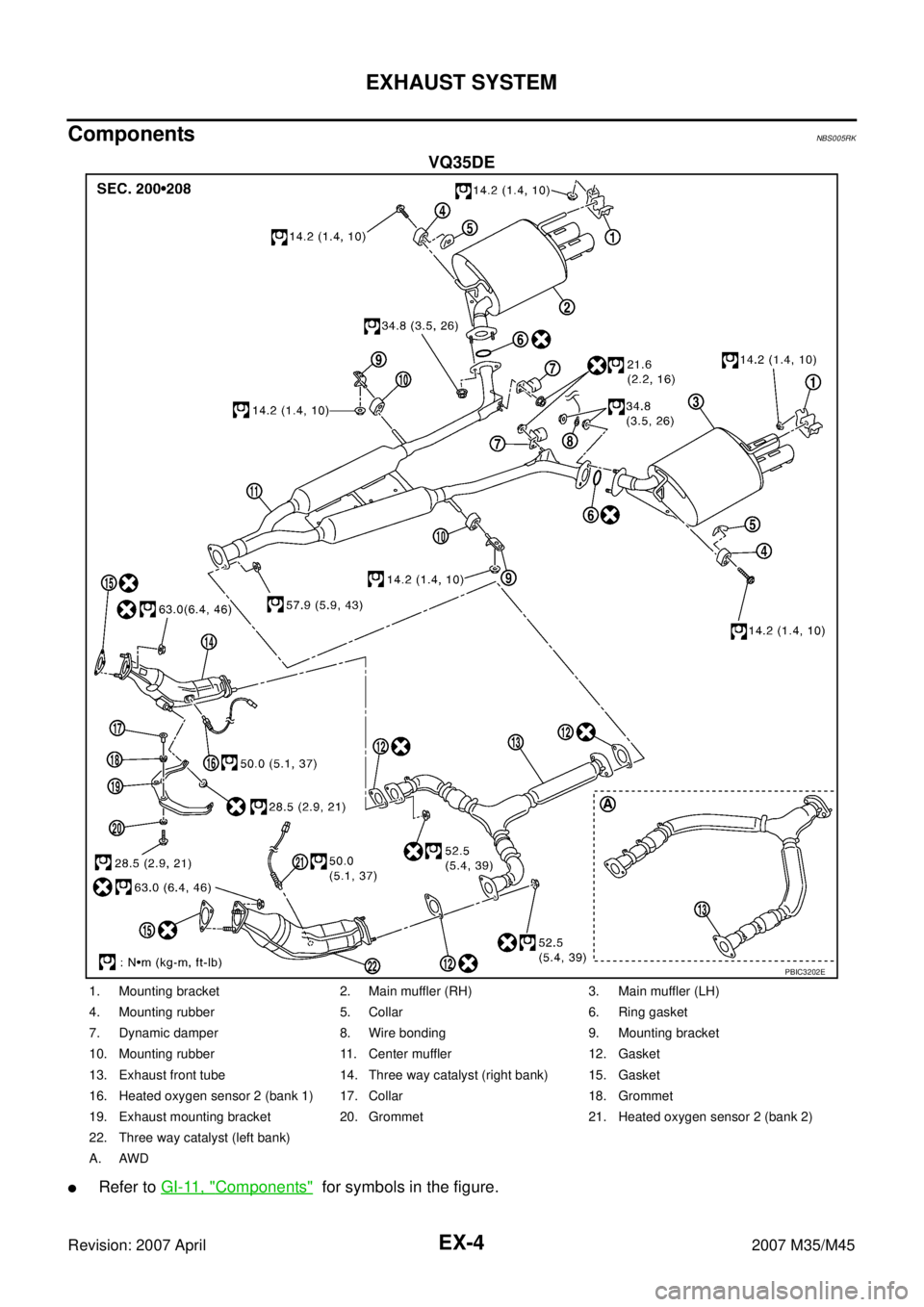
ComponentsNBS005RK
VQ35DE
�Refer to GI-11, "Components" for symbols in the figure.
PBIC3202E
1. Mounting bracket 2. Main muffler (RH) 3. Main muffler (LH)
4. Mounting rubber 5. Collar 6. Ring gasket
7. Dynamic damper 8. Wire bonding 9. Mounting bracket
10. Mounting rubber 11. Center muffler 12. Gasket
13. Exhaust front tube 14. Three way catalyst (right bank) 15. Gasket
16. Heated oxygen sensor 2 (bank 1) 17. Collar 18. Grommet
19. Exhaust mounting bracket 20. Grommet 21. Heated oxygen sensor 2 (bank 2)
22. Three way catalyst (left bank)
A. AWD
Page 3035 of 4647
EX-6
EXHAUST SYSTEM
Revision: 2007 April2007 M35/M45
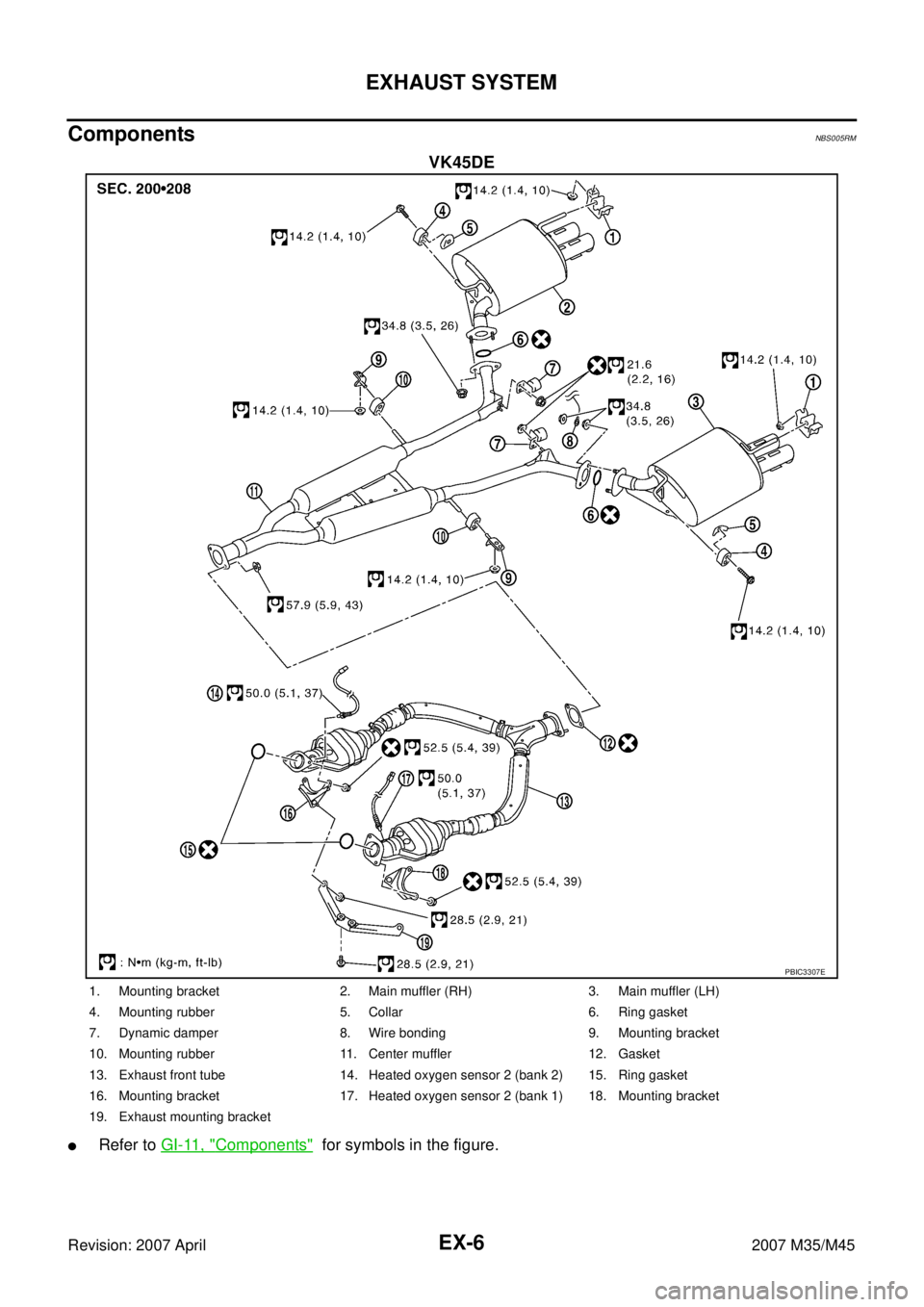
ComponentsNBS005RM
VK45DE
�Refer to GI-11, "Components" for symbols in the figure.
PBIC3307E
1. Mounting bracket 2. Main muffler (RH) 3. Main muffler (LH)
4. Mounting rubber 5. Collar 6. Ring gasket
7. Dynamic damper 8. Wire bonding 9. Mounting bracket
10. Mounting rubber 11. Center muffler 12. Gasket
13. Exhaust front tube 14. Heated oxygen sensor 2 (bank 2) 15. Ring gasket
16. Mounting bracket 17. Heated oxygen sensor 2 (bank 1) 18. Mounting bracket
19. Exhaust mounting bracket
Page 3042 of 4647

FRONT WHEEL HUB AND KNUCKLE
FAX-5
C
E
F
G
H
I
J
K
L
MA
B
FA X
Revision: 2007 April2007 M35/M45
FRONT WHEEL HUB AND KNUCKLEPFP:40202
On-Vehicle Inspection NDS000FF
Make sure that the mounting conditions (looseness, backlash) of each component and component conditions
(wear, damage) are normal.
WHEEL BEARING INSPECTION
�Move wheel hub and bearing assembly in the axial direction by hand. Make sure there is no looseness of
wheel bearing.
�Rotate wheel hub and make sure that is no unusual noise or other irregular conditions. If there is any of
irregular conditions, replace wheel hub and bearing assembly
Removal and InstallationNDS000FG
COMPONENT
REMOVAL
Wheel Hub and Bearing Assembly
1. Remove tires from vehicle with power tool.
2. Remove wheel sensor from steering knuckle. Refer to BRC-54, "
WHEEL SENSOR" .
CAUTION:
Do not pull on wheel sensor harness.
3. Remove brake hose bracket. Refer to BR-11, "
BRAKE TUBE AND HOSE" .
4. Remove torque member fixing bolts with power tool. Hang torque member in a place where it will not inter-
fere with work. Refer to BR-22, "
FRONT DISC BRAKE" .
CAUTION:
Do not depress brake pedal while brake caliper is removed.Axial end play : 0.05 mm (0.002 in) or less
1. Steering knuckle 2. Cotter pin 3. Splash guard
4. Wheel hub and bearing assembly 5. Washer
A: AWD models
Refer to GI-11, "
Components" , for the symbols in the figure.
SDIA3256E
Page 3048 of 4647

FRONT DRIVE SHAFT
FAX-11
C
E
F
G
H
I
J
K
L
MA
B
FA X
Revision: 2007 April2007 M35/M45
34. Install wheel sensor to steering knuckle. Refer to BRC-54, "WHEEL SENSOR" .
35. Tighten the hub lock nut to the specified torque. Refer to FA X - 5 , "
COMPONENT" .
36. Install cotter pin.
37. Install tires to vehicle.
Removal and InstallationNDS000G1
COMPONENT
REMOVAL
1. Remove tires from vehicle with power tool.
2. Remove wheel sensor from steering knuckle. Refer to BRC-54, "
WHEEL SENSOR" .
CAUTION:
Do not pull on wheel sensor harness.
3. Remove brake hose bracket. Refer to BR-11, "
BRAKE TUBE AND HOSE" .
4. Remove torque member fixing bolts with power tool. Hang torque member in a place where it will not inter-
fere with work. Refer to BR-22, "
FRONT DISC BRAKE" .
CAUTION:
Do not depress brake pedal while brake caliper is removed.
5. Remove disc rotor. Refer to FAX-5, "
Removal and Installation" .
6. Remove cotter pin, then loosen hub lock nut with power tool.
7. Separate wheel hub and bearing assembly from drive shaft by
lightly tapping the end with a hammer (suitable tool) and a wood
block, and then remove hub lock nut.
CAUTION:
�Do not place drive shaft joint at an extreme angle. Also be
careful not to overextend slide joint.
�Do not allow drive shaft to hang down without support for
housing (or joint sub-assembly), shaft and the other
parts.
NOTE:
Use a puller (suitable tool) if wheel hub and drive shaft cannot
be separated even after performing the above procedure.
1. Drive shaft (RH side) 2. Drive shaft (LH side) 3. Cotter pin
Refer to GI-11, "
Components" , for the symbols un the figure.
SDIA3042J
SDIA1821E
Page 3050 of 4647

FRONT DRIVE SHAFT
FAX-13
C
E
F
G
H
I
J
K
L
MA
B
FA X
Revision: 2007 April2007 M35/M45
Disassembly and AssemblyNDS000G2
COMPONENT
DISASSEMBLY
Front Final Drive Side
1. Place shaft in a vise.
CAUTION:
Protect shaft when securing in a vise using aluminum or copper plates.
2. Remove boot bands, and then remove boot from housing.
3. If plug needs to be removed, move boot to wheel side, and dive it out with a plastic hammer. (LH side)
4. Put matching marks on housing and shaft, and then pull out housing from shaft.
CAUTION:
Use paint or similar substance for matching marks. Do not scratch the surfaces.
5. Put matching marks on the shaft and spider assembly.
CAUTION:
Use paint or similar substance for matching marks. Do not
scratch the surfaces.
1. Joint sub-assembly 2. Circular clip 3. Boot band
4. Boot 5. Shaft 6. Spider assembly
7. Snap ring 8. Housing 9. Dust shield
10. Plug
A: RH side
B: LH side
Refer to GI-11, "
Components" and the following for the symbols in the figure.
: NISSAN genuine grease or equivalent
SDIA3043J
SFA963
Page 3068 of 4647

FRONT FINAL DRIVE ASSEMBLY
FFD-13
C
E
F
G
H
I
J
K
L
MA
B
FFD
Revision: 2007 April2007 M35/M45
FRONT FINAL DRIVE ASSEMBLYPFP:38500
Removal and InstallationNDS000EU
COMPONENTS
REMOVAL
1. Remove front drive shaft both. Refer to FA X - 11 , "Removal and Installation" .
2. Remove front crossbar with power tool.
3. Separate steering outer socket and steering knuckle. Refer to PS-19, "
POWER STEERING GEAR AND
LINKAGE" .
4. Remove side shaft.
5. Remove three way catalyst (right bank) with power tool. Refer to EX-3, "
EXHAUST SYSTEM" .
6. Remove front propeller shaft. Refer to PR-5, "
Removal and Installation" .
7. Separate EPS solenoid valve connector.
8. Separate power steering hydraulic line.
9. Remove stabilizer assembly with power tool. Refer to FSU-36, "
Removal and Installation" .
10. Separate steering lower joint and steering gear assembly. Refer to PS-19, "
POWER STEERING GEAR
AND LINKAGE" .
11. Set a suitable jack to engine.
12. Remove front suspension member with power tool. Refer to FSU-27, "
Removal and Installation" .
13. Remove breather hose and tube.
14. Remove engine mounting bracket (RH) (Lower) and engine mounting insulator (RH) with power tool.
Refer to EM-119, "
Removal and Installation (AWD Models)" .
1. Front final drive assembly 2. Side shaft 3. Bushing
4. Front propeller shaft 5. Breather hose 6. Breather tube
7. Breather connector 8. Engine mounting bracket (RH)
(Lower)9. Engine mounting insulator (RH)
Refer to GI-11, "
Components" , for the symbols in the figure.
PDIA0789J
Page 3071 of 4647

FFD-16
FRONT FINAL DRIVE ASSEMBLY
Revision: 2007 April2007 M35/M45
ASSEMBLY INSPECTION AND ADJUSTMENT
�Before inspection and adjustment, drain gear oil.
Total Preload Torque
1. Rotate drive pinion back and forth 2 to 3 times to check for unusual noise and rotation malfunction.
2. Rotate drive pinion at least 20 times to check for smooth opera-
tion of the bearing.
3. Measure total preload with preload gauge.
NOTE:
Total preload torque = Pinion bearing preload torque + Side
bearing preload torque
�If measured value is out of the specification, disassemble it to
check and adjust each part. Adjust the pinion bearing preload and side bearing preload.
Adjust the pinion bearing preload first, then adjust the side bearing preload.
34. Side shaft bearing 35. Extension tube retainer 36. Side shaft oil seal
37. Dust sealed 38. Side shaft
A: Oil seal lip
B: Screw hole
Refer to GI-11, "
Components" and the followings for the symbols in the figure.
:Apply gear oil.
:Apply anti-corrosion oil.
:Apply Genuine Silicone RTV or equivalent. Refer to GI-47, "
Recommended Chemical Products and Sealants" .
:Apply Genuine Medium Strength Thread Locking Sealant or equivalent. Refer to GI-47, "
Recommended Chemical
Products and Sealants" .
Tool number A: ST3127S000 (J-25765-A)
Total preload torque:
1.56 - 2.65 N·m (0.16 - 0.27 kg-m, 14 - 23 in-lb)
PDIA0792J
When the preload torque is large
On pinion bearings: Decrease the drive pinion bearing adjusting washer and drive pinion
adjusting washer thickness. Refer to FFD-36, "
Drive Pinion Bearing
Adjusting Washer" and FFD-36, "Drive Pinion Adjusting Washer" .
On side bearings: Increase the side bearing adjusting shim thickness. Refer to FFD-36,
"Side Bearing Adjusting Shim" .
When the preload torque is small
On pinion bearings: Increase the drive pinion bearing adjusting washer and drive pinion
adjusting washer thickness. Refer to FFD-36, "
Drive Pinion Bearing
Adjusting Washer" and FFD-36, "Drive Pinion Adjusting Washer" .
On side bearings: Decrease the side bearing adjusting shim thickness. Refer to FFD-36,
"Side Bearing Adjusting Shim" .