Page 1629 of 4647
![INFINITI M35 2007 Factory Service Manual EC-100
[VQ35DE]
TROUBLE DIAGNOSIS
Revision: 2007 April2007 M35/M45
1 - 6: The numbers refer to the order of inspection.
(continued on next page)Camshaft position sensor (PHASE) circuit 3 2EC-371
Vehic](/manual-img/42/57024/w960_57024-1628.png "INFINITI M35 2007 Factory Service Manual EC-100
[VQ35DE]
TROUBLE DIAGNOSIS
Revision: 2007 April2007 M35/M45
1 - 6: The numbers refer to the order of inspection.
(continued on next page)Camshaft position sensor (PHASE) circuit 3 2EC-371
Vehic")
EC-100
[VQ35DE]
TROUBLE DIAGNOSIS
Revision: 2007 April2007 M35/M45
1 - 6: The numbers refer to the order of inspection.
(continued on next page)Camshaft position sensor (PHASE) circuit 3 2EC-371
Vehicle speed signal circuit 2 3 3 3EC-468
Power steering pressure sensor circuit 2 3 3EC-474
ECM 22333333333EC-479,
EC-483
Intake valve timing control solenoid valve cir-
cuit32 13223 3EC-185
PNP switch circuit 3 3 3 3 3EC-491
Refrigerant pressure sensor circuit 2 3 3 4EC-704
Electrical load signal circuit 3EC-667
Air conditioner circuit 223333333 3 2AT C - 4 0
ABS actuator and electric unit (control unit) 4BRC-10
SYMPTOM
Reference
page
HARD/NO START/RESTART (EXCP. HA)
ENGINE STALL
HESITATION/SURGING/FLAT SPOT
SPARK KNOCK/DETONATION
LACK OF POWER/POOR ACCELERATION
HIGH IDLE/LOW IDLE
ROUGH IDLE/HUNTING
IDLING VIBRATION
SLOW/NO RETURN TO IDLE
OVERHEATS/WATER TEMPERATURE HIGH
EXCESSIVE FUEL CONSUMPTION
EXCESSIVE OIL CONSUMPTION
BATTERY DEAD (UNDER CHARGE)
Warranty symptom code AA AB AC AD AE AF AG AH AJ AK AL AM HA
Page 1632 of 4647
![INFINITI M35 2007 Factory Service Manual TROUBLE DIAGNOSIS
EC-103
[VQ35DE]
C
D
E
F
G
H
I
J
K
L
MA
EC
Revision: 2007 April2007 M35/M45
Engine Control Component Parts LocationNBS004T2
1. IPDM E/R 2. ICC brake hold relay
(ICC models only)3. Bat](/manual-img/42/57024/w960_57024-1631.png "INFINITI M35 2007 Factory Service Manual TROUBLE DIAGNOSIS
EC-103
[VQ35DE]
C
D
E
F
G
H
I
J
K
L
MA
EC
Revision: 2007 April2007 M35/M45
Engine Control Component Parts LocationNBS004T2
1. IPDM E/R 2. ICC brake hold relay
(ICC models only)3. Bat")
TROUBLE DIAGNOSIS
EC-103
[VQ35DE]
C
D
E
F
G
H
I
J
K
L
MA
EC
Revision: 2007 April2007 M35/M45
Engine Control Component Parts LocationNBS004T2
1. IPDM E/R 2. ICC brake hold relay
(ICC models only)3. Battery current sensor
4. Cooling fan relay 5. Power steering pressure sensor 6. Refrigerant pressure sensor
7. Intake valve timing control solenoid
valve (bank 1)8. Cooling fan motor-2 9. Cooling fan control module
10. Intake valve timing control solenoid
valve (bank 2)11. Cooling fan motor-1 12. Mass air flow sensor
(with built in intake air temperature
sensor)
13. Ignition coil (with power transistor)
and spark plug (bank 2)14. Camshaft position sensor (PHASE)
(Bank 2)15. Electric throttle control actuator
(with built in throttle position sensor,
throttle control motor)
16. Fuel injector (bank 2) 17. Knock sensor 18. Fuel injector (bank 1)
19. EVAP canister purge volume con-
trol solenoid valve20. Camshaft position sensor (PHASE)
(Bank 1)21. Engine coolant temperature sensor
22. Ignition coil (with power transistor)
and spark plug (bank 1)23. EVAP service port
PBIB2781E
Page 1635 of 4647
EC-106
[VQ35DE]
TROUBLE DIAGNOSIS
Revision: 2007 April2007 M35/M45
: Vehicle front
1. Power steering pressure sensor 2. Intake valve timing control solenoid
valve3. Ignition coil harness connector
(Bank 1)
4. Ignition coil harness connector
(Bank 2)5. Intake valve timing control solenoid
valve6. EVAP service port
7. EVAP canister purge volume con-
trol solenoid valve
PBIB2789E
Page 1645 of 4647
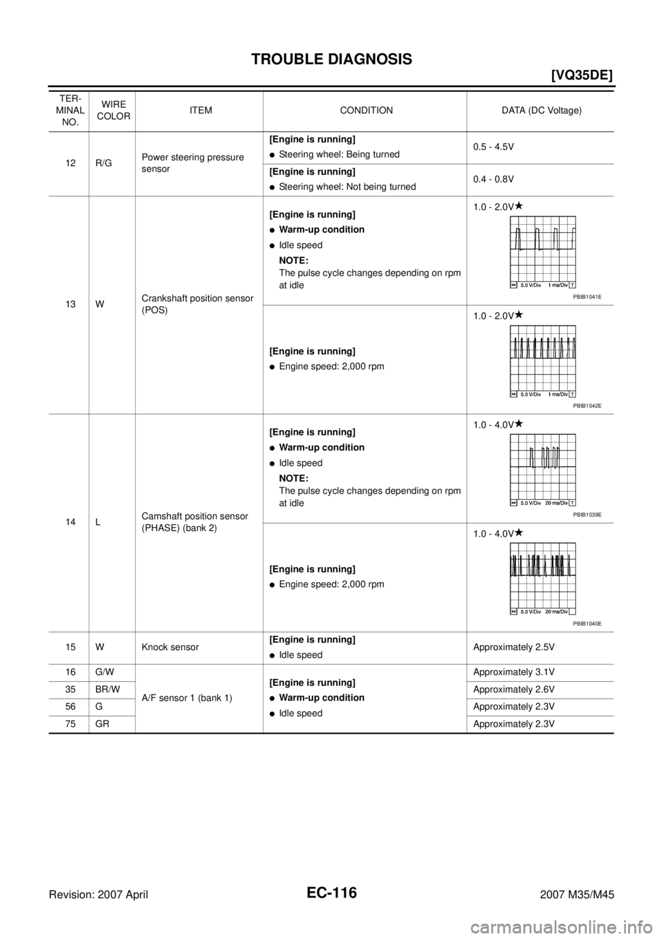
EC-116
[VQ35DE]
TROUBLE DIAGNOSIS
Revision: 2007 April2007 M35/M45
12 R/GPower steering pressure
sensor[Engine is running]�Steering wheel: Being turned0.5 - 4.5V
[Engine is running]
�Steering wheel: Not being turned0.4 - 0.8V
13 WCrankshaft position sensor
(POS)[Engine is running]
�Warm-up condition
�Idle speed
NOTE:
The pulse cycle changes depending on rpm
at idle1.0 - 2.0V
[Engine is running]
�Engine speed: 2,000 rpm1.0 - 2.0V
14 LCamshaft position sensor
(PHASE) (bank 2)[Engine is running]
�Warm-up condition
�Idle speed
NOTE:
The pulse cycle changes depending on rpm
at idle1.0 - 4.0V
[Engine is running]
�Engine speed: 2,000 rpm1.0 - 4.0V
15 W Knock sensor[Engine is running]
�Idle speedApproximately 2.5V
16 G/W
A/F sensor 1 (bank 1)[Engine is running]
�Warm-up condition
�Idle speedApproximately 3.1V
35 BR/WApproximately 2.6V
56 GApproximately 2.3V
75 GRApproximately 2.3V TER-
MINAL
NO.WIRE
COLORITEM CONDITION DATA (DC Voltage)
PBIB1041E
PBIB1042E
PBIB1039E
PBIB1040E
Page 1648 of 4647
![INFINITI M35 2007 Factory Service Manual TROUBLE DIAGNOSIS
EC-119
[VQ35DE]
C
D
E
F
G
H
I
J
K
L
MA
EC
Revision: 2007 April2007 M35/M45
50 W Throttle position sensor 1[Ignition switch: ON]
�Engine stopped
�Selector lever: D
�Accelerator pedal:](/manual-img/42/57024/w960_57024-1647.png "INFINITI M35 2007 Factory Service Manual TROUBLE DIAGNOSIS
EC-119
[VQ35DE]
C
D
E
F
G
H
I
J
K
L
MA
EC
Revision: 2007 April2007 M35/M45
50 W Throttle position sensor 1[Ignition switch: ON]
�Engine stopped
�Selector lever: D
�Accelerator pedal:")
TROUBLE DIAGNOSIS
EC-119
[VQ35DE]
C
D
E
F
G
H
I
J
K
L
MA
EC
Revision: 2007 April2007 M35/M45
50 W Throttle position sensor 1[Ignition switch: ON]
�Engine stopped
�Selector lever: D
�Accelerator pedal: Fully releasedMore than 0.36V
[Ignition switch: ON]
�Engine stopped
�Selector lever: D
�Accelerator pedal: Fully depressedLess than 4.75V
51 W Mass air flow sensor[Engine is running]
�Warm-up condition
�Idle speed0.9 - 1.2V
[Engine is running]
�Warm-up condition
�Engine speed: 2,500 rpm1.6 - 1.9V
55 WHeated oxygen sensor 2
(bank 2)[Engine is running]
�Revving engine from idle to 3,000 rpm
quickly after the following conditions are met
–Engine: After warming up
–Keeping the engine speed between 3,500
and 4,000 rpm for 1 minute and at idle for 1
minute under no load0 - Approximately 1.0V
57 GR/L
A/F sensor 1 (bank 2)[Engine is running]
�Warm-up condition
�Idle speedApproximately 2.6V
58 LG/BApproximately 2.3V
76 W/LApproximately 3.1V
77 YApproximately 2.3V
60
61
62
79
80
81V/W
P
Y/R
GR/R
GR/B
G/RIgnition signal No. 5
Ignition signal No. 3
Ignition signal No. 1
Ignition signal No. 6
Ignition signal No. 4
Ignition signal No. 2[Engine is running]
�Warm-up condition
�Idle speed
NOTE:
The pulse cycle changes depending on rpm
at idle0 - 0.2V
[Engine is running]
�Warm-up condition
�Engine speed: 2,000 rpm0.1 - 0.4V
66 BSensor ground
(Throttle position sensor)[Engine is running]
�Warm-up condition
�Idle speedApproximately 0V
67 B/W Sensor ground[Engine is running]
�Warm-up condition
�Idle speedApproximately 0V
68 L/YSensor power supply
(Power steering pressure
sensor)[Ignition switch: ON]Approximately 5V TER-
MINAL
NO.WIRE
COLORITEM CONDITION DATA (DC Voltage)
PBIB0044E
PBIB0045E
Page 1653 of 4647
![INFINITI M35 2007 Factory Service Manual EC-124
[VQ35DE]
TROUBLE DIAGNOSIS
Revision: 2007 April2007 M35/M45
ENGINE CONTROL COMPONENT PARTS/CONTROL SYSTEMS APPLICATION
ItemDIAGNOSTIC TEST MODE
WORK
SUP-
PORTSELF-DIAGNOS-
TIC RESULTS
DATA
MO](/manual-img/42/57024/w960_57024-1652.png "INFINITI M35 2007 Factory Service Manual EC-124
[VQ35DE]
TROUBLE DIAGNOSIS
Revision: 2007 April2007 M35/M45
ENGINE CONTROL COMPONENT PARTS/CONTROL SYSTEMS APPLICATION
ItemDIAGNOSTIC TEST MODE
WORK
SUP-
PORTSELF-DIAGNOS-
TIC RESULTS
DATA
MO")
EC-124
[VQ35DE]
TROUBLE DIAGNOSIS
Revision: 2007 April2007 M35/M45
ENGINE CONTROL COMPONENT PARTS/CONTROL SYSTEMS APPLICATION
ItemDIAGNOSTIC TEST MODE
WORK
SUP-
PORTSELF-DIAGNOS-
TIC RESULTS
DATA
MONI-
TORDATA
MONI-
TOR
(SPEC)ACTIVE
TESTDTC & SRT
CONFIRMATION
DTC*1FREEZE
FRAME
DATA*2SRT
STATUSDTC
WORK
SUP-
PORT
ENGINE CONTROL COMPONENT PARTS
INPUT
Crankshaft position sensor (POS)××××
Camshaft position sensor
(PHASE)××××
Mass air flow sensor×××
Engine coolant temperature sen-
sor×××××
Air fuel ratio (A/F) sensor 1×××××
Heated oxygen sensor 2×××××
Wheel sensor××××
Accelerator pedal position sensor×××
Throttle position sensor××××
Fuel tank temperature sensor××××
EVAP control system pressure
sensor×××
Intake air temperature sensor××××
Knock sensor×
Refrigerant pressure sensor××
Closed throttle position switch
(accelerator pedal position sensor
signal)××
Air conditioner switch××
Park/neutral position (PNP) switch×××
Stop lamp switch×××
Power steering pressure sensor×××
Battery voltage××
Load signal××
Fuel level sensor×××
Battery current sensor×××
ICC steering switch×××
ASCD steering switch×××
ICC brake switch×××
ASCD brake switch×××
Page 1657 of 4647
![INFINITI M35 2007 Factory Service Manual EC-128
[VQ35DE]
TROUBLE DIAGNOSIS
Revision: 2007 April2007 M35/M45
THRTL SEN 1 [V]××�The throttle position sensor signal voltage
is displayed.�THRTL SEN 2 signal is converted by
ECM internally. Th](/manual-img/42/57024/w960_57024-1656.png "INFINITI M35 2007 Factory Service Manual EC-128
[VQ35DE]
TROUBLE DIAGNOSIS
Revision: 2007 April2007 M35/M45
THRTL SEN 1 [V]××�The throttle position sensor signal voltage
is displayed.�THRTL SEN 2 signal is converted by
ECM internally. Th")
EC-128
[VQ35DE]
TROUBLE DIAGNOSIS
Revision: 2007 April2007 M35/M45
THRTL SEN 1 [V]××�The throttle position sensor signal voltage
is displayed.�THRTL SEN 2 signal is converted by
ECM internally. Thus, they differs from
ECM terminal voltage signal. THRTL SEN 2 [V]×
FUEL T/TMP SE
[°C] or [°F]×
�The fuel temperature (determined by the
signal voltage of the fuel tank tempera-
ture sensor) is displayed.
INT/A TEMP SE
[°C] or [°F]××
�The intake air temperature (determined
by the signal voltage of the intake air tem-
perature sensor) is indicated.
EVAP SYS PRES
[V]×
�The signal voltage of EVAP control sys-
tem pressure sensor is displayed.
FPCM DR VOLT
[V]
�The voltage between fuel pump and
FPCM is displayed.
FUEL LEVEL SE
[V]×
�The signal voltage of the fuel level sensor
is displayed.
START SIGNAL
[ON/OFF]××
�Indicates start signal status [ON/OFF]
computed by the ECM according to the
signals of engine speed and battery volt-
age.
�After starting the engine, [OFF] is dis-
played regardless of the starter signal.
CLSD THL POS
[ON/OFF]××
�Indicates idle position [ON/OFF] com-
puted by ECM according to the accelera-
tor pedal position sensor signal.
AIR COND SIG
[ON/OFF]××
�Indicates [ON/OFF] condition of the air
conditioner switch as determined by the
air conditioner signal.
P/N POSI SW
[ON/OFF]××
�Indicates [ON/OFF] condition from the
park/neutral position (PNP) switch signal.
PW/ST SIGNAL
[ON/OFF]××
�[ON/OFF] condition of the power steering
system (determined by the signal voltage
of the power steering pressure sensor
signal) is indicated.
LOAD SIGNAL
[ON/OFF]××
�Indicates [ON/OFF] condition from the
electrical load signal.
ON: Rear window defogger switch is ON
and/or lighting switch is in 2nd position.
OFF: Both rear window defogger switch
and lighting switch are OFF.
IGNITION SW
[ON/OFF]×
�Indicates [ON/OFF] condition from igni-
tion switch signal.
HEATER FAN SW
[ON/OFF]×
�Indicates [ON/OFF] condition from the
heater fan switch signal.
BRAKE SW
[ON/OFF]×
�Indicates [ON/OFF] condition from the
stop lamp switch signal.
INJ PULSE-B1
[msec]×
�Indicates the actual fuel injection pulse
width compensated by ECM according to
the input signals.�When the engine is stopped, a certain
computed value is indicated.
INJ PULSE-B2
[msec]
IGN TIMING
[BTDC]×
�Indicates the ignition timing computed by
ECM according to the input signals.�When the engine is stopped, a certain
value is indicated.
CAL/LD VALUE [%]
�“Calculated load value” indicates the
value of the current air flow divided by
peak air flow. Monitored item
[Unit]ECM
INPUT
SIG-
NALSMAIN
SIG-
NALSDescription Remarks
Page 1678 of 4647
![INFINITI M35 2007 Factory Service Manual TROUBLE DIAGNOSIS - SPECIFICATION VALUE
EC-149
[VQ35DE]
C
D
E
F
G
H
I
J
K
L
MA
EC
Revision: 2007 April2007 M35/M45
16. CHECK “A/F ALPHA-B1”, “A/F ALPHA-B2”
1. Start engine.
2. Select “A/F AL](/manual-img/42/57024/w960_57024-1677.png "INFINITI M35 2007 Factory Service Manual TROUBLE DIAGNOSIS - SPECIFICATION VALUE
EC-149
[VQ35DE]
C
D
E
F
G
H
I
J
K
L
MA
EC
Revision: 2007 April2007 M35/M45
16. CHECK “A/F ALPHA-B1”, “A/F ALPHA-B2”
1. Start engine.
2. Select “A/F AL")
TROUBLE DIAGNOSIS - SPECIFICATION VALUE
EC-149
[VQ35DE]
C
D
E
F
G
H
I
J
K
L
MA
EC
Revision: 2007 April2007 M35/M45
16. CHECK “A/F ALPHA-B1”, “A/F ALPHA-B2”
1. Start engine.
2. Select “A/F ALPHA-B1”, “A/F ALPHA-B2” in “DATA MONITOR (SPEC)” mode, and make sure that the
each indication is within the SP value.
OK or NG
OK >>INSPECTION END
NG >> Detect malfunctioning part according to EC-99, "
Symptom Matrix Chart" .
17. CHECK “B/FUEL SCHDL”
Select “B/FUEL SCHDL” in “DATA MONITOR (SPEC)” mode, and
make sure that the indication is within the SP value.
OK or NG
OK >>INSPECTION END
NG (More than the SP value)>>GO TO 18.
NG (Less than the SP value)>>GO TO 25.
18. DETECT MALFUNCTIONING PART
1. Check for the cause of large engine friction. Refer to the following.
–Engine oil level is too high
–Engine oil viscosity
–Belt tension of power steering, alternator, A/C compressor, etc. is excessive
–Noise from engine
–Noise from transmission, etc.
2. Check for the cause of insufficient combustion. Refer to the following.
–Valve clearance malfunction
–Intake valve timing control function malfunction
–Camshaft sprocket installation malfunction, etc.
>> Repair or replace malfunctioning part, and then GO TO 30.
19. CHECK INTAKE SYSTEM
Check for the cause of uneven air flow through mass air flow sensor. Refer to the following.
�Crushed air ducts
�Malfunctioning seal of air cleaner element
�Uneven dirt of air cleaner element
�Improper specification of intake air system
OK or NG
OK >> GO TO 21.
NG >> Repair or replace malfunctioning part, and then GO TO 20.
PBIB2332E
![INFINITI M35 2007 Factory Service Manual EC-106
[VQ35DE]
TROUBLE DIAGNOSIS
Revision: 2007 April2007 M35/M45
: Vehicle front
1. Power steering pressure sensor 2. Intake valve timing control solenoid
valve3. Ignition coil harness connector
(](/manual-img/42/57024/w960_57024-1634.png "INFINITI M35 2007 Factory Service Manual EC-106
[VQ35DE]
TROUBLE DIAGNOSIS
Revision: 2007 April2007 M35/M45
: Vehicle front
1. Power steering pressure sensor 2. Intake valve timing control solenoid
valve3. Ignition coil harness connector
(")