Page 4563 of 4647
WT-14
TROUBLE DIAGNOSES
Revision: 2007 April2007 M35/M45
Wiring Diagram — T/WARN —NES000JW
TEWB0008E
Page 4592 of 4647

WW-1
WIPER, WASHER & HORN
K ELECTRICAL
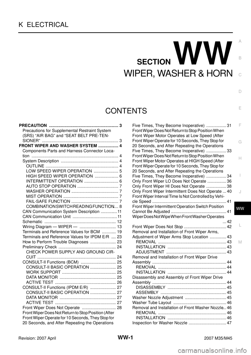
CONTENTS
C
D
E
F
G
H
I
J
L
M
SECTION WW
A
B
WW
Revision: 2007 April2007 M35/M45
WIPER, WASHER & HORN
PRECAUTION ............................................................ 3
Precautions for Supplemental Restraint System
(SRS) “AIR BAG” and “SEAT BELT PRE-TEN-
SIONER” .................................................................. 3
FRONT WIPER AND WASHER SYSTEM .................. 4
Components Parts and Harness Connector Loca-
tion ........................................................................... 4
System Description .................................................. 4
OUTLINE ............................................................... 4
LOW SPEED WIPER OPERATION ...................... 5
HIGH SPEED WIPER OPERATION ..................... 6
INTERMITTENT OPERATION .............................. 6
AUTO STOP OPERATION .................................... 7
WASHER OPERATION ......................................... 7
MIST OPERATION ................................................ 7
FAIL-SAFE FUNCTION ......................................... 7
COMBINATION SWITCH READING FUNCTION ..... 8
CAN Communication System Description ............... 11
CAN Communication Unit ....................................... 11
Schematic .............................................................. 12
Wiring Diagram — WIPER — ................................ 13
Terminals and Reference Values for BCM ............. 19
Terminals and Reference Values for IPDM E/R ..... 23
How to Perform Trouble Diagnoses ....................... 23
Preliminary Check .................................................. 24
CHECK POWER SUPPLY AND GROUND CIR-
CUIT .................................................................... 24
CONSULT-II Functions (BCM) ............................... 25
CONSULT-II BASIC OPERATION ....................... 25
WORK SUPPORT ............................................... 25
DATA MONITOR ................................................. 25
ACTIVE TEST ..................................................... 26
CONSULT-II Functions (IPDM E/R) ....................... 27
CONSULT-II BASIC OPERATION ....................... 27
DATA MONITOR ................................................. 27
ACTIVE TEST ..................................................... 27
Front Wiper Does Not Operate .............................. 28
Front Wiper Does Not Return to Stop Position (After
Front Wiper Operate for 10 Seconds, They Stop for
20 Seconds, and After Repeating the Operations Five Times, They Become Inoperative) .................. 31
Front Wiper Does Not Return to Stop Position When
Front Wiper Motor Operates at Low Speed (After
Front Wiper Operate for 10 Seconds, They Stop for
20 Seconds, and After Repeating the Operations
Five Times, They Become Inoperative) .................. 33
Front Wiper Does Not Return to Stop Position When
Front Wiper Motor Operates at HIGH Speed (After
Front Wiper Operate for 10 Seconds, They Stop for
20 Seconds, and After Repeating the Operations
Five Times, They Become Inoperative) .................. 34
Only Front Wiper LO Does Not Operate ................. 36
Only Front Wiper HI Does Not Operate .................. 38
Only Front Wiper Intermittent Does Not Operate ... 40
Front Wiper Interval Time Is Not Controlled by Vehi-
cle Speed ................................................................ 41
Front Wiper Intermittent Operation Switch Position
Cannot Be Adjusted ................................................ 41
Wiper Does Not Wipe When Front Washer Operates
... 42
Front Wiper Does Not Stop ..................................... 42
Removal and Installation of Front Wiper Arms,
Adjustment of Wiper Arms Stop Location ............... 43
REMOVAL ........................................................... 43
INSTALLATION ................................................... 43
ADJUSTMENT .................................................... 43
Removal and Installation of Front Wiper Drive
Assembly ................................................................ 44
REMOVAL ........................................................... 44
INSTALLATION ................................................... 44
Disassembly and Assembly of Front Wiper Drive
Assembly ................................................................ 44
DISASSEMBLY ................................................... 45
ASSEMBLY ......................................................... 45
Washer Nozzle Adjustment .................................... 45
Washer Tube Layout .............................................. 46
Removal and Installation of Front Washer Nozzle ... 46
REMOVAL ........................................................... 46
INSTALLATION ................................................... 46
Inspection for Washer Nozzle ................................. 47
Page 4593 of 4647

WW-2Revision: 2007 April2007 M35/M45 CHECK VALVE INSPECTION ............................. 47
Inspection of Front Wiper and Washer Switch Circuit ... 47
Removal and Installation of Front Wiper and Washer
Switch ..................................................................... 47
REMOVAL ........................................................... 47
INSTALLATION .................................................... 47
Removal and Installation of Washer Tank .............. 48
REMOVAL ........................................................... 48
INSTALLATION .................................................... 48
Removal and Installation of Washer Pump ............. 49
REMOVAL ........................................................... 49
INSTALLATION .................................................... 49
CIGARETTE LIGHTER ............................................. 50
Wiring Diagram — CIGAR — ................................. 50
Removal and Installation ........................................ 51
REMOVAL ........................................................... 51
INSTALLATION .................................................... 51POWER SOCKET ..................................................... 52
Wiring Diagram — P/SCKT — ................................ 52
Removal and Installation of Center Console Box
Power Socket .......................................................... 53
REMOVAL ............................................................ 53
INSTALLATION .................................................... 53
Removal and Installation of Center Console Box
Rear Side Power Socket ......................................... 53
REMOVAL ............................................................ 53
INSTALLATION .................................................... 53
HORN ........................................................................ 54
Wiring Diagram — HORN — .................................. 54
Removal and Installation ......................................... 55
REMOVAL ............................................................ 55
INSTALLATION .................................................... 55
Page 4604 of 4647
FRONT WIPER AND WASHER SYSTEM
WW-13
C
D
E
F
G
H
I
J
L
MA
B
WW
Revision: 2007 April2007 M35/M45
Wiring Diagram — WIPER —NKS003WG
TKWT5090E
Page 4615 of 4647

WW-24
FRONT WIPER AND WASHER SYSTEM
Revision: 2007 April2007 M35/M45
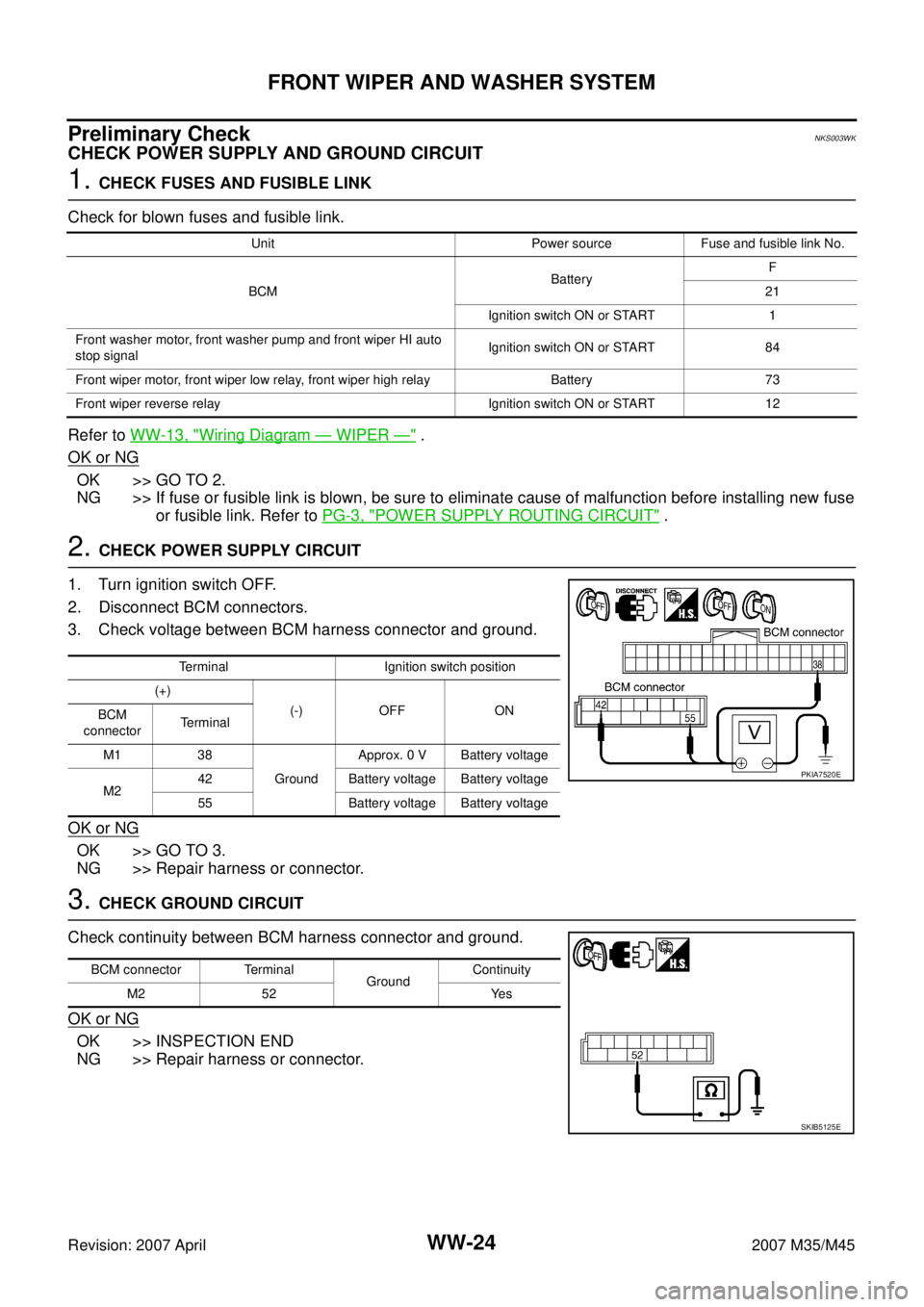
Preliminary CheckNKS003WK
CHECK POWER SUPPLY AND GROUND CIRCUIT
1. CHECK FUSES AND FUSIBLE LINK
Check for blown fuses and fusible link.
Refer to WW-13, "
Wiring Diagram — WIPER —" .
OK or NG
OK >> GO TO 2.
NG >> If fuse or fusible link is blown, be sure to eliminate cause of malfunction before installing new fuse
or fusible link. Refer to PG-3, "
POWER SUPPLY ROUTING CIRCUIT" .
2. CHECK POWER SUPPLY CIRCUIT
1. Turn ignition switch OFF.
2. Disconnect BCM connectors.
3. Check voltage between BCM harness connector and ground.
OK or NG
OK >> GO TO 3.
NG >> Repair harness or connector.
3. CHECK GROUND CIRCUIT
Check continuity between BCM harness connector and ground.
OK or NG
OK >> INSPECTION END
NG >> Repair harness or connector.
Unit Power source Fuse and fusible link No.
BCMBatteryF
21
Ignition switch ON or START 1
Front washer motor, front washer pump and front wiper HI auto
stop signalIgnition switch ON or START 84
Front wiper motor, front wiper low relay, front wiper high relay Battery 73
Front wiper reverse relay Ignition switch ON or START 12
Terminal Ignition switch position
(+)
(-) OFF ON
BCM
connectorTerminal
M1 38
GroundApprox. 0 V Battery voltage
M242 Battery voltage Battery voltage
55 Battery voltage Battery voltage
PKIA7520E
BCM connector Terminal
GroundContinuity
M2 52 Yes
SKIB5125E
Page 4641 of 4647
WW-50
CIGARETTE LIGHTER
Revision: 2007 April2007 M35/M45
CIGARETTE LIGHTERPFP:35330
Wiring Diagram — CIGAR —NKS003X9
TKWT3219E
Page 4643 of 4647
WW-52
POWER SOCKET
Revision: 2007 April2007 M35/M45
POWER SOCKETPFP:253A2
Wiring Diagram — P/SCKT —NKS003XB
TKWT3220E
Page 4645 of 4647
WW-54
HORN
Revision: 2007 April2007 M35/M45
HORNPFP:25610
Wiring Diagram — HORN —NKS003XE
TKWT3221E