Page 4601 of 4647
WW-10
FRONT WIPER AND WASHER SYSTEM
Revision: 2007 April2007 M35/M45
Operation Mode
Combination switch reading function has operation modes shown below.
1. Normal status
–When BCM is not in sleep status, OUTPUT terminals (1-5) each turn ON-OFF every 10 ms.
2. Sleep status
–When BCM is in sleep status, transistors of OUTPUT 1 and 5 stop the output, and BCM enters low current
consumption mode. OUTPUT 2, 3, and 4 turn ON-OFF every 60 ms, and only input from lighting switch
system is accepted.
PKIC0272E
Page 4610 of 4647

FRONT WIPER AND WASHER SYSTEM
WW-19
C
D
E
F
G
H
I
J
L
MA
B
WW
Revision: 2007 April2007 M35/M45
Terminals and Reference Values for BCMNKS003WH
CAUTION:
�Check combination switch system terminal waveform under the loaded condition with lighting
switch, turn signal switch and wiper switch OFF not to be fluctuated by overloaded.
�Turn wiper dial position to 4 except when checking waveform or voltage of wiper dial position.
Wiper dial position can be confirmed on CONSULT-II. Refer to WW-25, "
DATA MONITOR" .
Terminal
No.Wire
colorSignal nameMeasuring condition
Reference value
Ignition
switchOperation or condition
4R/GCombination
switch input 3ONLighting, turn, wiper
OFF
(Wiper dial position 4)
Any of several con-
ditions below
�Front wiper SW MIST
�Front wiper SW INT
�Front wiper SW LO
Approx. 1.0 V
OFF Approx. 0 V
5YCombination
switch input 2ONLighting, turn, wiper
OFF
Any of several con-
ditions below
�Front washer switch
(Wiper dial position 4)
�Wiper dial position 1
�Wiper dial position 5
�Wiper dial position 6
Approx. 1.0 V
OFF
(Wiper dial position 4)Approx. 0 V
PKIB4957J
PKIB4957J
Page 4611 of 4647
WW-20
FRONT WIPER AND WASHER SYSTEM
Revision: 2007 April2007 M35/M45
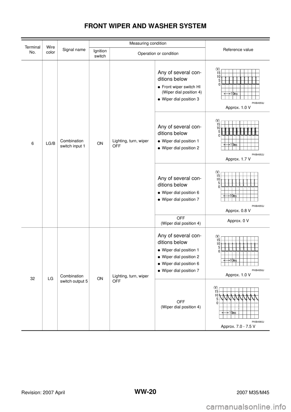
6LG/BCombination
switch input 1ONLighting, turn, wiper
OFF
Any of several con-
ditions below
�Front wiper switch HI
(Wiper dial position 4)
�Wiper dial position 3
Approx. 1.0 V
Any of several con-
ditions below
�Wiper dial position 1
�Wiper dial position 2
Approx. 1.7 V
Any of several con-
ditions below
�Wiper dial position 6
�Wiper dial position 7
Approx. 0.8 V
OFF
(Wiper dial position 4)Approx. 0 V
32 LGCombination
switch output 5ONLighting, turn, wiper
OFF
Any of several con-
ditions below
�Wiper dial position 1
�Wiper dial position 2
�Wiper dial position 6
�Wiper dial position 7
Approx. 1.0 V
OFF
(Wiper dial position 4)
Approx. 7.0 - 7.5 V Te r m i n a l
No.Wire
colorSignal nameMeasuring condition
Reference value
Ignition
switchOperation or condition
PKIB4959J
PKIB4952J
PKIB4955J
PKIB4956J
PKIB4960J
Page 4612 of 4647
FRONT WIPER AND WASHER SYSTEM
WW-21
C
D
E
F
G
H
I
J
L
MA
B
WW
Revision: 2007 April2007 M35/M45
33 GRCombination
switch output 4ONLighting, turn, wiper
OFF
(Wiper dial position 4)
Any of several con-
ditions below
�Wiper dial position 1
�Wiper dial position 5
�Wiper dial position 6
Approx. 1.2 V
OFF
(Wiper dial position 4)
Approx. 7.0 - 7.5 V
34 LCombination
switch output 3ONLighting, turn, wiper
OFF
Any of several con-
ditions below
�Wiper dial position 1
�Wiper dial position 2
�Wiper dial position 3
Approx. 1.2 V
OFF
(Wiper dial position 4)
Approx. 7.0 - 7.5 V
35 SBCombination
switch output 2ONLighting, turn, wiper
OFF
(Wiper dial position 4)
Any of several con-
ditions below
�Front wiper switch INT
�Front wiper switch HI
Approx. 1.2 V
OFF
Approx. 7.0 - 7.5 V Terminal
No.Wire
colorSignal nameMeasuring condition
Reference value
Ignition
switchOperation or condition
PKIB4958J
PKIB4960J
PKIB4958J
PKIB4960J
PKIB4958J
PKIB4960J
Page 4613 of 4647
WW-22
FRONT WIPER AND WASHER SYSTEM
Revision: 2007 April2007 M35/M45
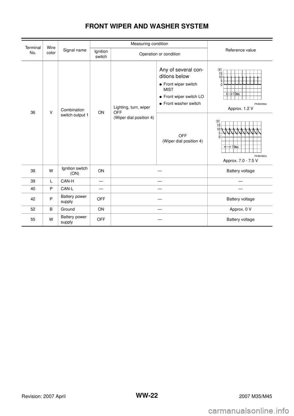
36 VCombination
switch output 1ONLighting, turn, wiper
OFF
(Wiper dial position 4)
Any of several con-
ditions below
�Front wiper switch
MIST
�Front wiper switch LO
�Front washer switch
Approx. 1.2 V
OFF
(Wiper dial position 4)
Approx. 7.0 - 7.5 V
38 WIgnition switch
(ON) ON — Battery voltage
39 L CAN-H — — —
40 P CAN-L — — —
42 PBattery power
supplyOFF — Battery voltage
52 B Ground ON — Approx. 0 V
55 WBattery power
supplyOFF — Battery voltage Te r m i n a l
No.Wire
colorSignal nameMeasuring condition
Reference value
Ignition
switchOperation or conditionPKIB4958J
PKIB4960J
Page 4641 of 4647
WW-50
CIGARETTE LIGHTER
Revision: 2007 April2007 M35/M45
CIGARETTE LIGHTERPFP:35330
Wiring Diagram — CIGAR —NKS003X9
TKWT3219E
Page 4642 of 4647
CIGARETTE LIGHTER
WW-51
C
D
E
F
G
H
I
J
L
MA
B
WW
Revision: 2007 April2007 M35/M45
Removal and InstallationNKS003XA
REMOVAL
1. Remove A/T console finisher. Refer to IP-10, "INSTRUMENT PANEL ASSEMBLY" .
2. Remove screws (A) from reverse side cigarette lighter socket.
3. Pull out cigarette lighter (1).
4. Insert a small screwdriver or similar tool between the cigarette
lighter socket (2) and cigarette lighter ring (3). Pull out cigarette
lighter socket (2).
INSTALLATION
Note the following, and installation is the reverse order of removal.
CAUTION:
Align notches of cigarette lighter ring and cigarette lighter socket when installing.
SKIB4207E
SKIB4262E


Any of several con-")