2007 INFINITI M35 roof
[x] Cancel search: roofPage 3323 of 4647
IDX-4
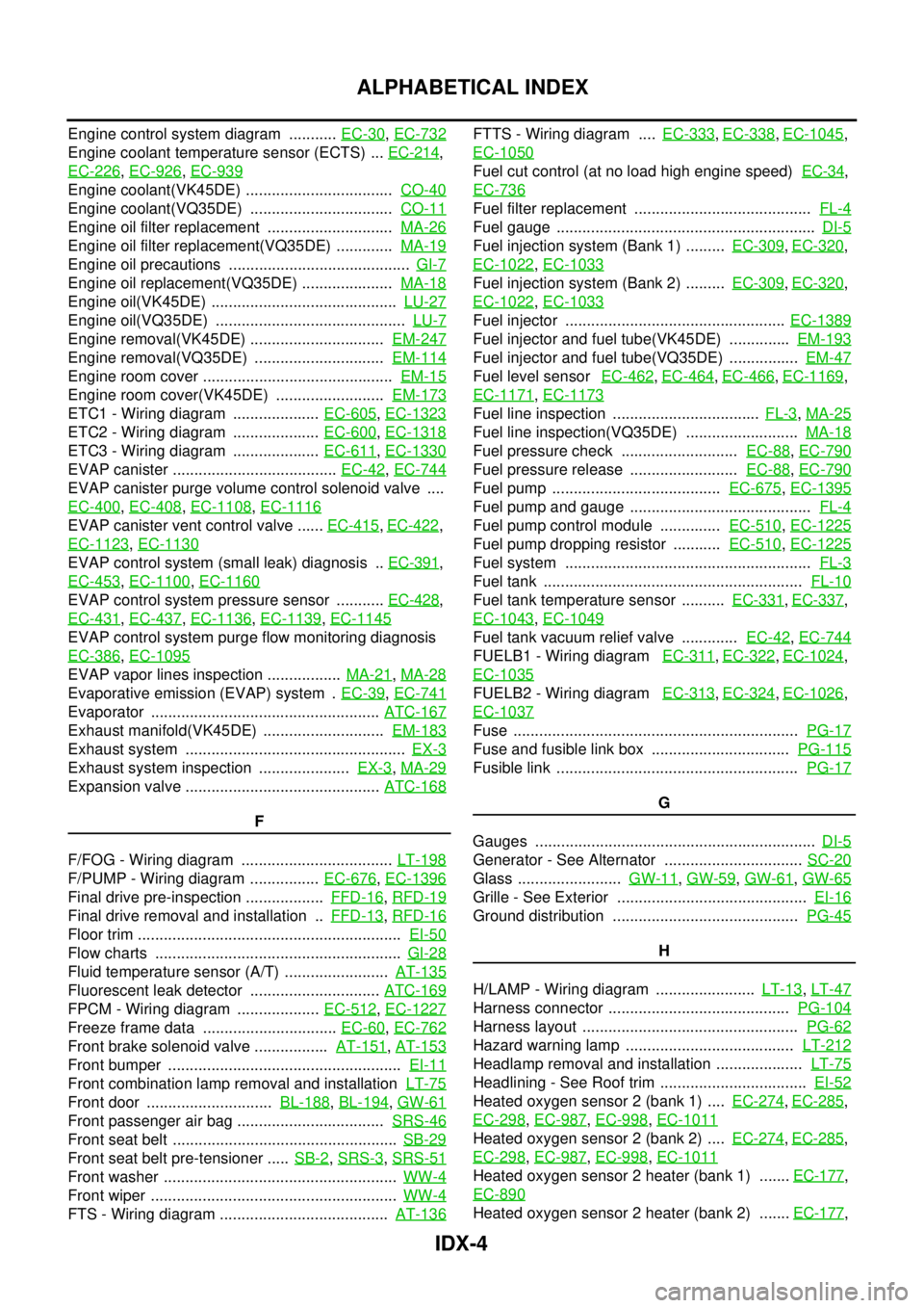
ALPHABETICAL INDEX
Engine control system diagram ........... EC-30, EC-732
Engine coolant temperature sensor (ECTS) ... EC-214,
EC-226
, EC-926, EC-939
Engine coolant(VK45DE) .................................. CO-40
Engine coolant(VQ35DE) ................................. CO-11
Engine oil filter replacement ............................. MA-26
Engine oil filter replacement(VQ35DE) ............. MA-19
Engine oil precautions .......................................... GI-7
Engine oil replacement(VQ35DE) ..................... MA-18
Engine oil(VK45DE) ........................................... LU-27
Engine oil(VQ35DE) ............................................ LU-7
Engine removal(VK45DE) ............................... EM-247
Engine removal(VQ35DE) .............................. EM-114
Engine room cover ............................................ EM-15
Engine room cover(VK45DE) ......................... EM-173
ETC1 - Wiring diagram .................... EC-605, EC-1323
ETC2 - Wiring diagram .................... EC-600, EC-1318
ETC3 - Wiring diagram .................... EC-611, EC-1330
EVAP canister ...................................... EC-42, EC-744
EVAP canister purge volume control solenoid valve ....
EC-400
, EC-408, EC-1108, EC-1116
EVAP canister vent control valve ...... EC-415, EC-422,
EC-1123
, EC-1130
EVAP control system (small leak) diagnosis .. EC-391,
EC-453
, EC-1100, EC-1160
EVAP control system pressure sensor ........... EC-428,
EC-431
, EC-437, EC-1136, EC-1139, EC-1145
EVAP control system purge flow monitoring diagnosis
EC-386
, EC-1095
EVAP vapor lines inspection ................. MA-21, MA-28
Evaporative emission (EVAP) system . EC-39, EC-741
Evaporator ..................................................... ATC-167
Exhaust manifold(VK45DE) ............................ EM-183
Exhaust system ................................................... EX-3
Exhaust system inspection ..................... EX-3, MA-29
Expansion valve ............................................. ATC-168
F
F/FOG - Wiring diagram ................................... LT-198
F/PUMP - Wiring diagram ................ EC-676, EC-1396
Final drive pre-inspection .................. FFD-16, RFD-19
Final drive removal and installation .. FFD-13, RFD-16
Floor trim ............................................................. EI-50
Flow charts ......................................................... GI-28
Fluid temperature sensor (A/T) ........................ AT-135
Fluorescent leak detector .............................. ATC-169
FPCM - Wiring diagram ................... EC-512, EC-1227
Freeze frame data ............................... EC-60, EC-762
Front brake solenoid valve ................. AT-151, AT-153
Front bumper ...................................................... EI-11
Front combination lamp removal and installation LT-75
Front door ............................. BL-188, BL-194, GW-61
Front passenger air bag .................................. SRS-46
Front seat belt .................................................... SB-29
Front seat belt pre-tensioner ..... SB-2, SRS-3, SRS-51
Front washer ...................................................... WW-4
Front wiper ......................................................... WW-4
FTS - Wiring diagram ....................................... AT-136
FTTS - Wiring diagram .... EC-333, EC-338, EC-1045,
EC-1050
Fuel cut control (at no load high engine speed) EC-34,
EC-736
Fuel filter replacement ......................................... FL-4
Fuel gauge ............................................................ DI-5
Fuel injection system (Bank 1) ......... EC-309, EC-320,
EC-1022
, EC-1033
Fuel injection system (Bank 2) ......... EC-309, EC-320,
EC-1022
, EC-1033
Fuel injector ................................................... EC-1389
Fuel injector and fuel tube(VK45DE) .............. EM-193
Fuel injector and fuel tube(VQ35DE) ................ EM-47
Fuel level sensor EC-462, EC-464, EC-466, EC-1169,
EC-1171
, EC-1173
Fuel line inspection .................................. FL-3, MA-25
Fuel line inspection(VQ35DE) .......................... MA-18
Fuel pressure check ........................... EC-88, EC-790
Fuel pressure release ......................... EC-88, EC-790
Fuel pump ....................................... EC-675, EC-1395
Fuel pump and gauge .......................................... FL-4
Fuel pump control module .............. EC-510, EC-1225
Fuel pump dropping resistor ........... EC-510, EC-1225
Fuel system ......................................................... FL-3
Fuel tank ............................................................ FL-10
Fuel tank temperature sensor .......... EC-331, EC-337,
EC-1043
, EC-1049
Fuel tank vacuum relief valve ............. EC-42, EC-744
FUELB1 - Wiring diagram EC-311, EC-322, EC-1024,
EC-1035
FUELB2 - Wiring diagram EC-313, EC-324, EC-1026,
EC-1037
Fuse .................................................................. PG-17
Fuse and fusible link box ................................ PG-115
Fusible link ........................................................ PG-17
G
Gauges ................................................................. DI-5
Generator - See Alternator ................................ SC-20
Glass ........................ GW-11, GW-59, GW-61, GW-65
Grille - See Exterior ............................................ EI-16
Ground distribution ........................................... PG-45
H
H/LAMP - Wiring diagram ....................... LT-13
, LT-47
Harness connector .......................................... PG-104
Harness layout .................................................. PG-62
Hazard warning lamp ....................................... LT-212
Headlamp removal and installation .................... LT-75
Headlining - See Roof trim .................................. EI-52
Heated oxygen sensor 2 (bank 1) .... EC-274, EC-285,
EC-298
, EC-987, EC-998, EC-1011
Heated oxygen sensor 2 (bank 2) .... EC-274, EC-285,
EC-298
, EC-987, EC-998, EC-1011
Heated oxygen sensor 2 heater (bank 1) ....... EC-177,
EC-890
Heated oxygen sensor 2 heater (bank 2) ....... EC-177,
Page 3326 of 4647
IDX-7
A
C
D
E
F
G
H
I
J
K
L B
IDX
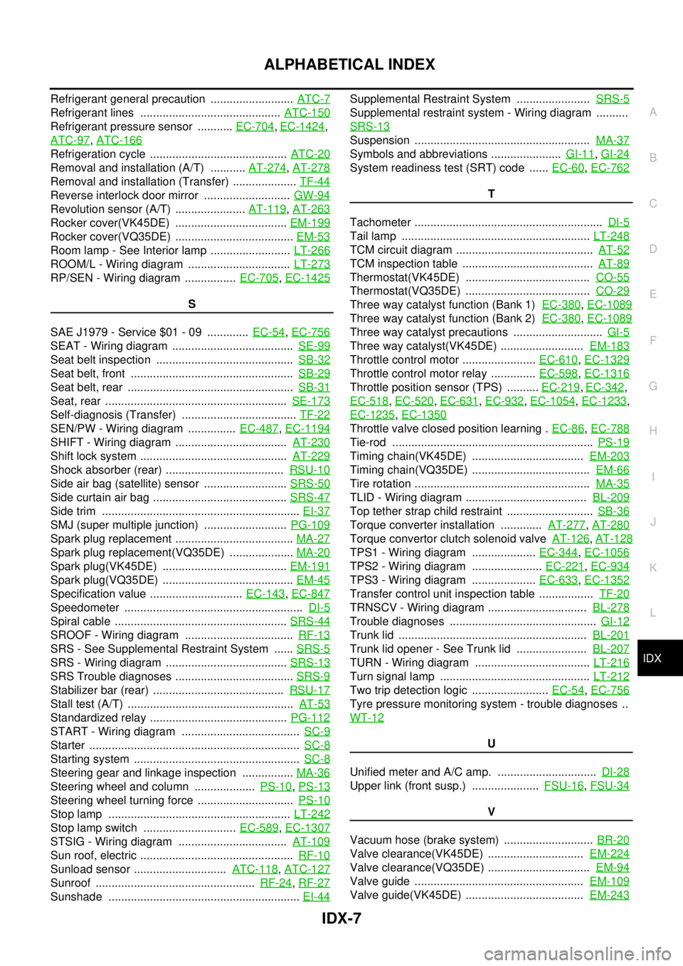
ALPHABETICAL INDEX
Refrigerant general precaution .......................... ATC-7
Refrigerant lines ............................................ ATC-150
Refrigerant pressure sensor ........... EC-704, EC-1424,
ATC-97
, ATC-166
Refrigeration cycle ........................................... ATC-20
Removal and installation (A/T) ........... AT-274, AT-278
Removal and installation (Transfer) .................... TF-44
Reverse interlock door mirror ........................... GW-94
Revolution sensor (A/T) ...................... AT-119, AT-263
Rocker cover(VK45DE) ................................... EM-199
Rocker cover(VQ35DE) ..................................... EM-53
Room lamp - See Interior lamp ......................... LT-266
ROOM/L - Wiring diagram ................................ LT-273
RP/SEN - Wiring diagram ................ EC-705, EC-1425
S
SAE J1979 - Service $01 - 09 ............. EC-54
, EC-756
SEAT - Wiring diagram ...................................... SE-99
Seat belt inspection ........................................... SB-32
Seat belt, front ................................................... SB-29
Seat belt, rear .................................................... SB-31
Seat, rear ......................................................... SE-173
Self-diagnosis (Transfer) .................................... TF-22
SEN/PW - Wiring diagram ............... EC-487, EC-1194
SHIFT - Wiring diagram ................................... AT-230
Shift lock system .............................................. AT-229
Shock absorber (rear) ..................................... RSU-10
Side air bag (satellite) sensor .......................... SRS-50
Side curtain air bag .......................................... SRS-47
Side trim .............................................................. EI-37
SMJ (super multiple junction) .......................... PG-109
Spark plug replacement ..................................... MA-27
Spark plug replacement(VQ35DE) .................... MA-20
Spark plug(VK45DE) ....................................... EM-191
Spark plug(VQ35DE) ......................................... EM-45
Specification value ............................. EC-143, EC-847
Speedometer ........................................................ DI-5
Spiral cable ...................................................... SRS-44
SROOF - Wiring diagram .................................. RF-13
SRS - See Supplemental Restraint System ...... SRS-5
SRS - Wiring diagram ...................................... SRS-13
SRS Trouble diagnoses ..................................... SRS-9
Stabilizer bar (rear) ......................................... RSU-17
Stall test (A/T) .................................................... AT-53
Standardized relay ........................................... PG-112
START - Wiring diagram ..................................... SC-9
Starter .................................................................. SC-8
Starting system .................................................... SC-8
Steering gear and linkage inspection ................ MA-36
Steering wheel and column ................... PS-10, PS-13
Steering wheel turning force .............................. PS-10
Stop lamp ......................................................... LT-242
Stop lamp switch ............................. EC-589, EC-1307
STSIG - Wiring diagram .................................. AT-109
Sun roof, electric ................................................ RF-10
Sunload sensor ............................. ATC-118, ATC-127
Sunroof .................................................. RF-24, RF-27
Sunshade ............................................................ EI-44
Supplemental Restraint System ....................... SRS-5
Supplemental restraint system - Wiring diagram ..........
SRS-13
Suspension ....................................................... MA-37
Symbols and abbreviations ...................... GI-11, GI-24
System readiness test (SRT) code ...... EC-60, EC-762
T
Tachometer ........................................................... DI-5
Tail lamp ........................................................... LT-248
TCM circuit diagram ........................................... AT-52
TCM inspection table ......................................... AT-89
Thermostat(VK45DE) ....................................... CO-55
Thermostat(VQ35DE) ....................................... CO-29
Three way catalyst function (Bank 1) EC-380, EC-1089
Three way catalyst function (Bank 2) EC-380, EC-1089
Three way catalyst precautions ............................ GI-5
Three way catalyst(VK45DE) .......................... EM-183
Throttle control motor ....................... EC-610, EC-1329
Throttle control motor relay .............. EC-598, EC-1316
Throttle position sensor (TPS) .......... EC-219, EC-342,
EC-518
, EC-520, EC-631, EC-932, EC-1054, EC-1233,
EC-1235
, EC-1350
Throttle valve closed position learning . EC-86, EC-788
Tie-rod ............................................................... PS-19
Timing chain(VK45DE) ................................... EM-203
Timing chain(VQ35DE) ..................................... EM-66
Tire rotation ....................................................... MA-35
TLID - Wiring diagram ...................................... BL-209
Top tether strap child restraint ........................... SB-36
Torque converter installation ............. AT-277, AT-280
Torque convertor clutch solenoid valve AT-126, AT-128
TPS1 - Wiring diagram .................... EC-344, EC-1056
TPS2 - Wiring diagram ...................... EC-221, EC-934
TPS3 - Wiring diagram .................... EC-633, EC-1352
Transfer control unit inspection table ................. TF-20
TRNSCV - Wiring diagram ............................... BL-278
Trouble diagnoses .............................................. GI-12
Trunk lid ........................................................... BL-201
Trunk lid opener - See Trunk lid ...................... BL-207
TURN - Wiring diagram .................................... LT-216
Turn signal lamp ............................................... LT-212
Two trip detection logic ........................ EC-54, EC-756
Tyre pressure monitoring system - trouble diagnoses ..
WT-12
U
Unified meter and A/C amp. ............................... DI-28
Upper link (front susp.) ..................... FSU-16, FSU-34
V
Vacuum hose (brake system) ............................ BR-20
Valve clearance(VK45DE) .............................. EM-224
Valve clearance(VQ35DE) ................................ EM-94
Valve guide ..................................................... EM-109
Valve guide(VK45DE) ..................................... EM-243
Page 3328 of 4647
IP-1
INSTRUMENT PANEL
I BODY
CONTENTS
C
D
E
F
G
H
J
K
L
M
SECTION IP
A
B
IP
Revision: 2007 April2007 M35/M45
INSTRUMENT PANEL
PRECAUTIONS .......................................................... 2
Precautions for Supplemental Restraint System
(SRS) “AIR BAG” and “SEAT BELT PRE-TEN-
SIONER” .................................................................. 2
Precautions .............................................................. 2
PREPARATION ........................................................... 3
Special Service Tools ............................................... 3
Commercial Service Tools ........................................ 3
SQUEAK AND RATTLE TROUBLE DIAGNOSES ..... 4
Work Flow ................................................................ 4
CUSTOMER INTERVIEW ..................................... 4
DUPLICATE THE NOISE AND TEST DRIVE ....... 5
CHECK RELATED SERVICE BULLETINS ........... 5
LOCATE THE NOISE AND IDENTIFY THE
ROOT CAUSE ...................................................... 5
REPAIR THE CAUSE ........................................... 5
CONFIRM THE REPAIR ....................................... 6
Generic Squeak and Rattle Troubleshooting ........... 6
INSTRUMENT PANEL .......................................... 6
CENTER CONSOLE ............................................. 6
DOORS ................................................................. 6TRUNK .................................................................. 7
SUNROOF/HEADLINING ..................................... 7
SEATS ................................................................... 7
UNDERHOOD ....................................................... 7
Diagnostic Worksheet ............................................... 8
INSTRUMENT PANEL ASSEMBLY ......................... 10
Component Parts Drawing ..................................... 10
Removal and Installation of Instrument Panel & Pad ... 11
REMOVAL ........................................................... 11
INSTALLATION ................................................... 14
Removal and Installation of Cluster Lid A ............... 15
REMOVAL ........................................................... 15
INSTALLATION ................................................... 16
Removal and Installation of Cluster Lid C .............. 17
REMOVAL ........................................................... 17
INSTALLATION ................................................... 18
Removal and Installation of Glove Box Assembly ... 18
REMOVAL ........................................................... 18
INSTALLATION ................................................... 18
Disassembly and Assembly .................................... 19
CENTER CONSOLE ASSEMBLY ....................... 19
Page 3334 of 4647
SQUEAK AND RATTLE TROUBLE DIAGNOSES
IP-7
C
D
E
F
G
H
J
K
L
MA
B
IP
Revision: 2007 April2007 M35/M45
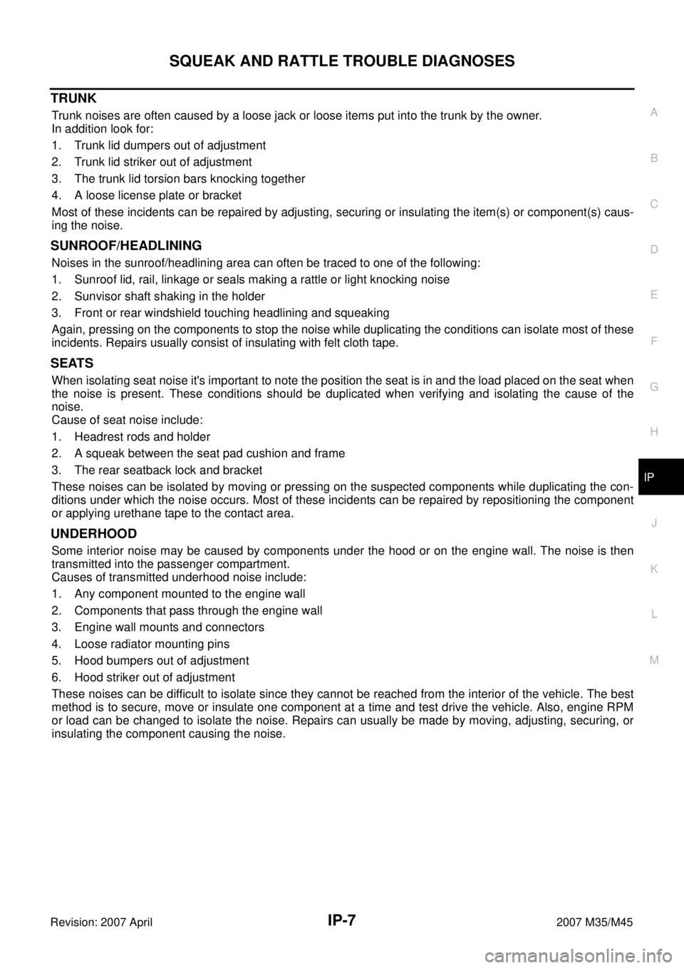
TRUNK
Trunk noises are often caused by a loose jack or loose items put into the trunk by the owner.
In addition look for:
1. Trunk lid dumpers out of adjustment
2. Trunk lid striker out of adjustment
3. The trunk lid torsion bars knocking together
4. A loose license plate or bracket
Most of these incidents can be repaired by adjusting, securing or insulating the item(s) or component(s) caus-
ing the noise.
SUNROOF/HEADLINING
Noises in the sunroof/headlining area can often be traced to one of the following:
1. Sunroof lid, rail, linkage or seals making a rattle or light knocking noise
2. Sunvisor shaft shaking in the holder
3. Front or rear windshield touching headlining and squeaking
Again, pressing on the components to stop the noise while duplicating the conditions can isolate most of these
incidents. Repairs usually consist of insulating with felt cloth tape.
SEATS
When isolating seat noise it's important to note the position the seat is in and the load placed on the seat when
the noise is present. These conditions should be duplicated when verifying and isolating the cause of the
noise.
Cause of seat noise include:
1. Headrest rods and holder
2. A squeak between the seat pad cushion and frame
3. The rear seatback lock and bracket
These noises can be isolated by moving or pressing on the suspected components while duplicating the con-
ditions under which the noise occurs. Most of these incidents can be repaired by repositioning the component
or applying urethane tape to the contact area.
UNDERHOOD
Some interior noise may be caused by components under the hood or on the engine wall. The noise is then
transmitted into the passenger compartment.
Causes of transmitted underhood noise include:
1. Any component mounted to the engine wall
2. Components that pass through the engine wall
3. Engine wall mounts and connectors
4. Loose radiator mounting pins
5. Hood bumpers out of adjustment
6. Hood striker out of adjustment
These noises can be difficult to isolate since they cannot be reached from the interior of the vehicle. The best
method is to secure, move or insulate one component at a time and test drive the vehicle. Also, engine RPM
or load can be changed to isolate the noise. Repairs can usually be made by moving, adjusting, securing, or
insulating the component causing the noise.
Page 3919 of 4647
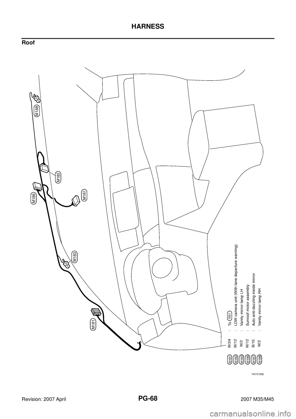
PG-68
HARNESS
Revision: 2007 April2007 M35/M45
Roof
TKIT0756E
Page 3948 of 4647
HARNESS
PG-97
C
D
E
F
G
H
I
J
L
MA
B
PG
Revision: 2007 April2007 M35/M45
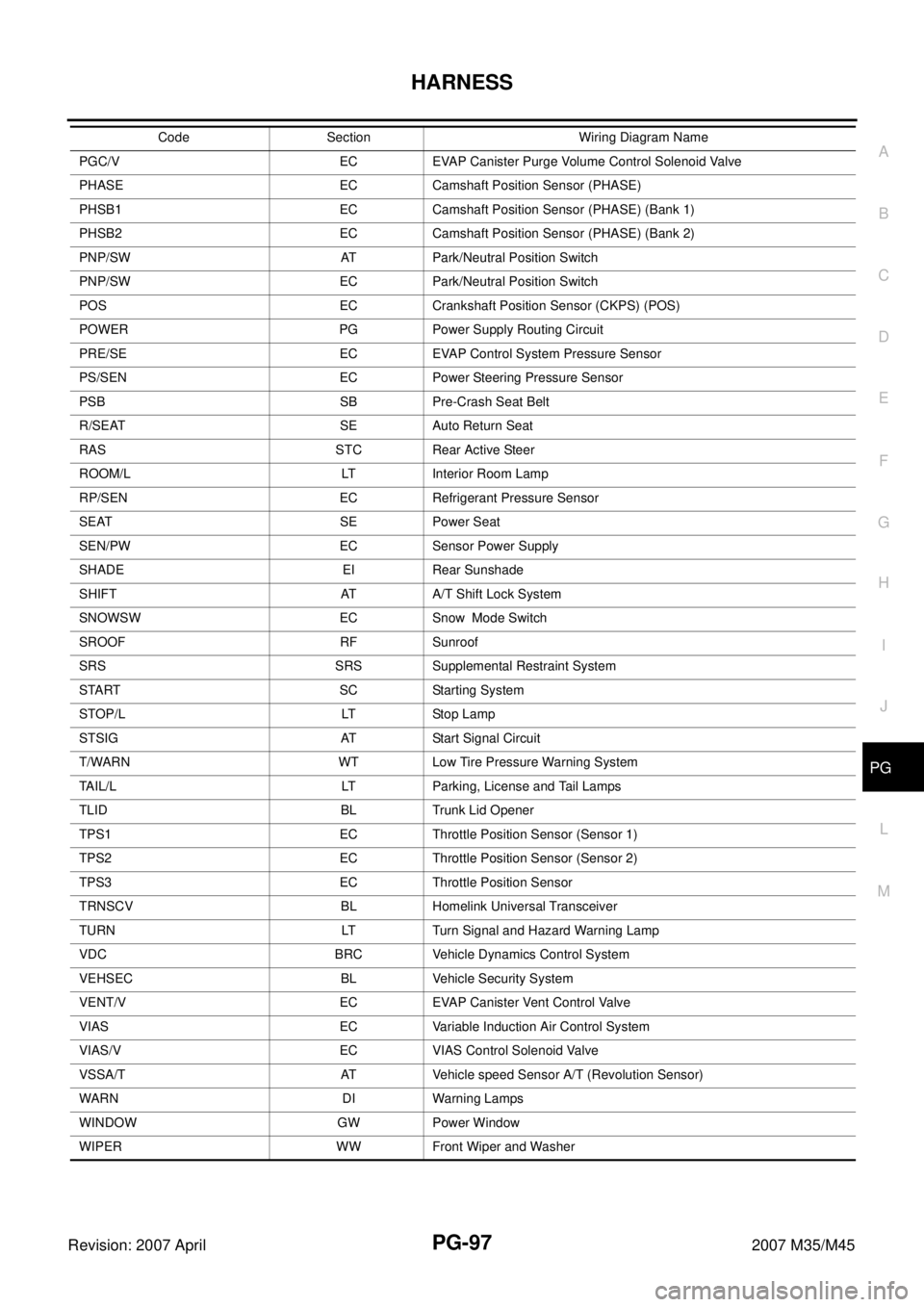
PGC/V EC EVAP Canister Purge Volume Control Solenoid Valve
PHASE EC Camshaft Position Sensor (PHASE)
PHSB1 EC Camshaft Position Sensor (PHASE) (Bank 1)
PHSB2 EC Camshaft Position Sensor (PHASE) (Bank 2)
PNP/SW AT Park/Neutral Position Switch
PNP/SW EC Park/Neutral Position Switch
POS EC Crankshaft Position Sensor (CKPS) (POS)
POWER PG Power Supply Routing Circuit
PRE/SE EC EVAP Control System Pressure Sensor
PS/SEN EC Power Steering Pressure Sensor
PSB SB Pre-Crash Seat Belt
R/SEAT SE Auto Return Seat
RAS STC Rear Active Steer
ROOM/L LT Interior Room Lamp
RP/SEN EC Refrigerant Pressure Sensor
SEAT SE Power Seat
SEN/PW EC Sensor Power Supply
SHADE EI Rear Sunshade
SHIFT AT A/T Shift Lock System
SNOWSW EC Snow Mode Switch
SROOF RF Sunroof
SRS SRS Supplemental Restraint System
START SC Starting System
STOP/L LT Stop Lamp
STSIG AT Start Signal Circuit
T/WARN WT Low Tire Pressure Warning System
TAIL/L LT Parking, License and Tail Lamps
TLID BL Trunk Lid Opener
TPS1 EC Throttle Position Sensor (Sensor 1)
TPS2 EC Throttle Position Sensor (Sensor 2)
TPS3 EC Throttle Position Sensor
TRNSCV BL Homelink Universal Transceiver
TURN LT Turn Signal and Hazard Warning Lamp
VDC BRC Vehicle Dynamics Control System
VEHSEC BL Vehicle Security System
VENT/V EC EVAP Canister Vent Control Valve
VIAS EC Variable Induction Air Control System
VIAS/V EC VIAS Control Solenoid Valve
VSSA/T AT Vehicle speed Sensor A/T (Revolution Sensor)
WARN DI Warning Lamps
WINDOW GW Power Window
WIPER WW Front Wiper and Washer Code Section Wiring Diagram Name
Page 4042 of 4647
RF-1
ROOF
I BODY
CONTENTS
C
D
E
F
G
H
J
K
L
M
SECTION RF
A
B
RF
Revision: 2007 April2007 M35/M45
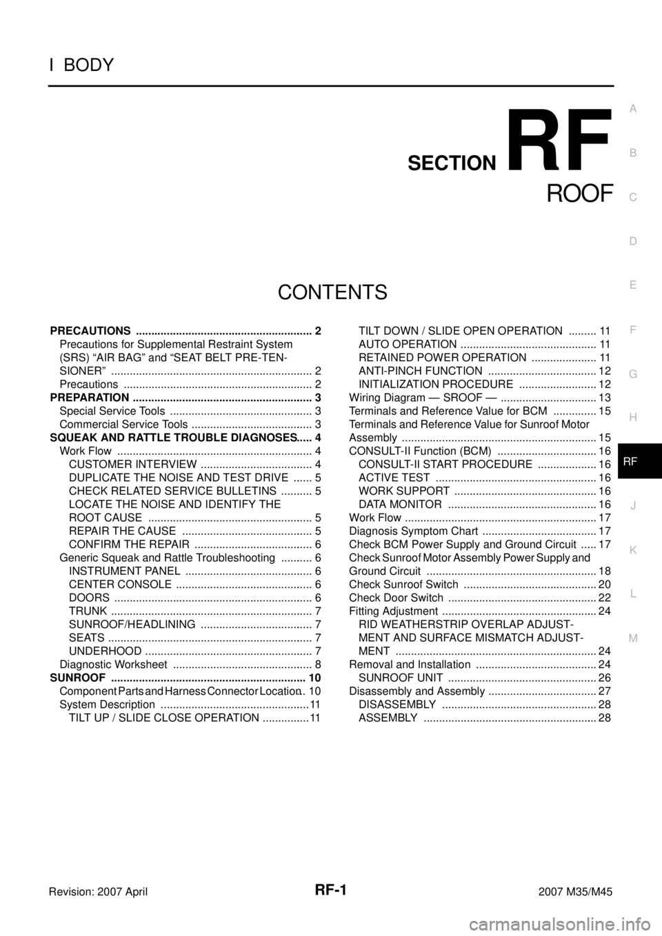
ROOF
PRECAUTIONS .......................................................... 2
Precautions for Supplemental Restraint System
(SRS) “AIR BAG” and “SEAT BELT PRE-TEN-
SIONER” .................................................................. 2
Precautions .............................................................. 2
PREPARATION ........................................................... 3
Special Service Tools ............................................... 3
Commercial Service Tools ........................................ 3
SQUEAK AND RATTLE TROUBLE DIAGNOSES ..... 4
Work Flow ................................................................ 4
CUSTOMER INTERVIEW ..................................... 4
DUPLICATE THE NOISE AND TEST DRIVE ....... 5
CHECK RELATED SERVICE BULLETINS ........... 5
LOCATE THE NOISE AND IDENTIFY THE
ROOT CAUSE ...................................................... 5
REPAIR THE CAUSE ........................................... 5
CONFIRM THE REPAIR ....................................... 6
Generic Squeak and Rattle Troubleshooting ........... 6
INSTRUMENT PANEL .......................................... 6
CENTER CONSOLE ............................................. 6
DOORS ................................................................. 6
TRUNK .................................................................. 7
SUNROOF/HEADLINING ..................................... 7
SEATS ................................................................... 7
UNDERHOOD ....................................................... 7
Diagnostic Worksheet .............................................. 8
SUNROOF ................................................................ 10
Component Parts and Harness Connector Location ... 10
System Description ................................................. 11
TILT UP / SLIDE CLOSE OPERATION ................ 11TILT DOWN / SLIDE OPEN OPERATION .......... 11
AUTO OPERATION ............................................. 11
RETAINED POWER OPERATION ...................... 11
ANTI-PINCH FUNCTION .................................... 12
INITIALIZATION PROCEDURE .......................... 12
Wiring Diagram — SROOF — ................................ 13
Terminals and Reference Value for BCM ............... 15
Terminals and Reference Value for Sunroof Motor
Assembly ................................................................ 15
CONSULT-II Function (BCM) ................................. 16
CONSULT-II START PROCEDURE .................... 16
ACTIVE TEST ..................................................... 16
WORK SUPPORT ............................................... 16
DATA MONITOR ................................................. 16
Work Flow ............................................................... 17
Diagnosis Symptom Chart ...................................... 17
Check BCM Power Supply and Ground Circuit ...... 17
Check Sunroof Motor Assembly Power Supply and
Ground Circuit ........................................................ 18
Check Sunroof Switch ............................................ 20
Check Door Switch ................................................. 22
Fitting Adjustment ................................................... 24
RID WEATHERSTRIP OVERLAP ADJUST-
MENT AND SURFACE MISMATCH ADJUST-
MENT .................................................................. 24
Removal and Installation ........................................ 24
SUNROOF UNIT ................................................. 26
Disassembly and Assembly .................................... 27
DISASSEMBLY ................................................... 28
ASSEMBLY ......................................................... 28
Page 4048 of 4647
SQUEAK AND RATTLE TROUBLE DIAGNOSES
RF-7
C
D
E
F
G
H
J
K
L
MA
B
RF
Revision: 2007 April2007 M35/M45
TRUNK
Trunk noises are often caused by a loose jack or loose items put into the trunk by the owner.
In addition look for:
1. Trunk lid dumpers out of adjustment
2. Trunk lid striker out of adjustment
3. The trunk lid torsion bars knocking together
4. A loose license plate or bracket
Most of these incidents can be repaired by adjusting, securing or insulating the item(s) or component(s) caus-
ing the noise.
SUNROOF/HEADLINING
Noises in the sunroof/headlining area can often be traced to one of the following:
1. Sunroof lid, rail, linkage or seals making a rattle or light knocking noise
2. Sunvisor shaft shaking in the holder
3. Front or rear windshield touching headlining and squeaking
Again, pressing on the components to stop the noise while duplicating the conditions can isolate most of these
incidents. Repairs usually consist of insulating with felt cloth tape.
SEATS
When isolating seat noise it's important to note the position the seat is in and the load placed on the seat when
the noise is present. These conditions should be duplicated when verifying and isolating the cause of the
noise.
Cause of seat noise include:
1. Headrest rods and holder
2. A squeak between the seat pad cushion and frame
3. The rear seatback lock and bracket
These noises can be isolated by moving or pressing on the suspected components while duplicating the con-
ditions under which the noise occurs. Most of these incidents can be repaired by repositioning the component
or applying urethane tape to the contact area.
UNDERHOOD
Some interior noise may be caused by components under the hood or on the engine wall. The noise is then
transmitted into the passenger compartment.
Causes of transmitted underhood noise include:
1. Any component mounted to the engine wall
2. Components that pass through the engine wall
3. Engine wall mounts and connectors
4. Loose radiator mounting pins
5. Hood bumpers out of adjustment
6. Hood striker out of adjustment
These noises can be difficult to isolate since they cannot be reached from the interior of the vehicle. The best
method is to secure, move or insulate one component at a time and test drive the vehicle. Also, engine RPM
or load can be changed to isolate the noise. Repairs can usually be made by moving, adjusting, securing, or
insulating the component causing the noise.