Page 4059 of 4647

RF-18
SUNROOF
Revision: 2007 April2007 M35/M45
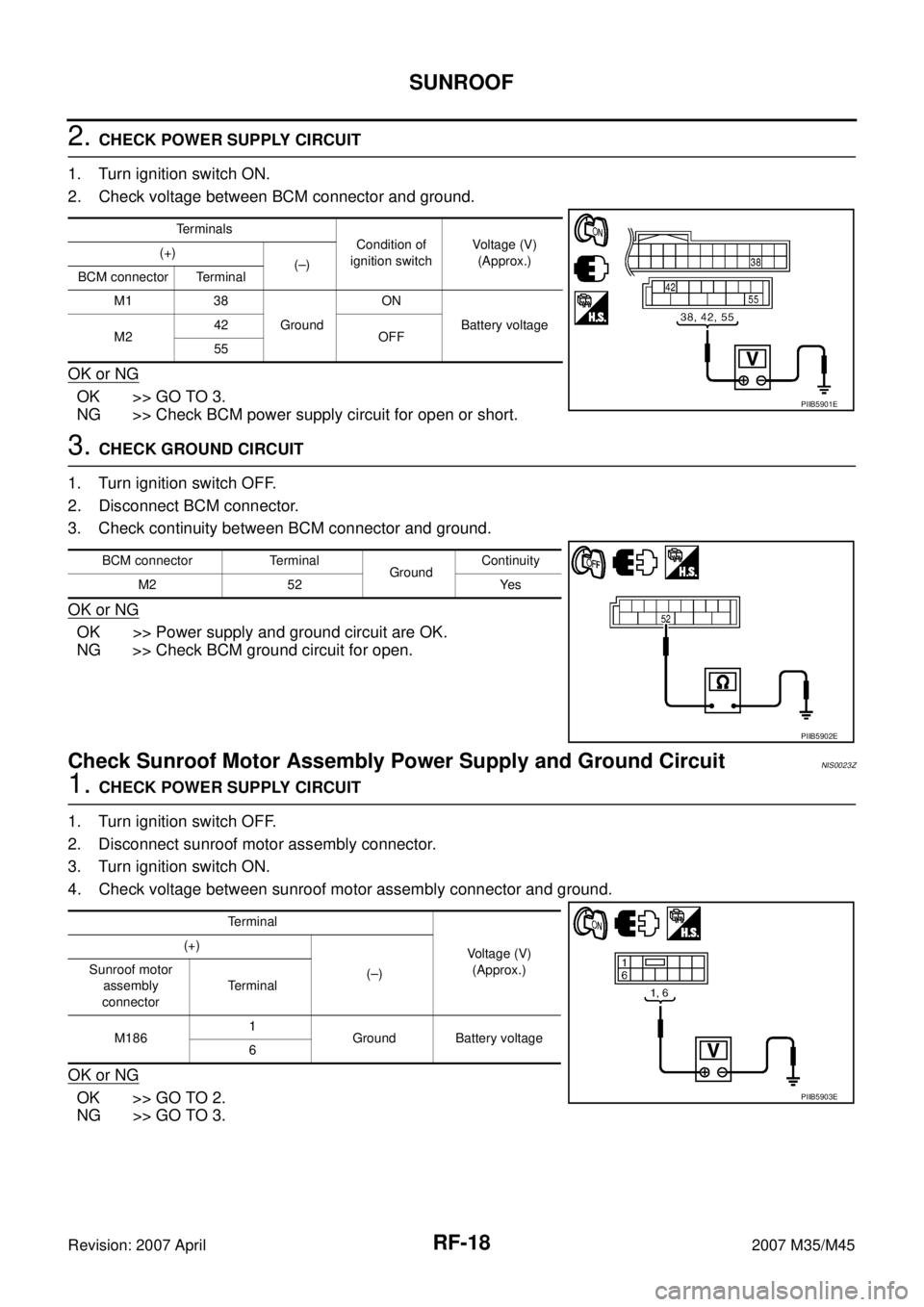
2. CHECK POWER SUPPLY CIRCUIT
1. Turn ignition switch ON.
2. Check voltage between BCM connector and ground.
OK or NG
OK >> GO TO 3.
NG >> Check BCM power supply circuit for open or short.
3. CHECK GROUND CIRCUIT
1. Turn ignition switch OFF.
2. Disconnect BCM connector.
3. Check continuity between BCM connector and ground.
OK or NG
OK >> Power supply and ground circuit are OK.
NG >> Check BCM ground circuit for open.
Check Sunroof Motor Assembly Power Supply and Ground Circuit NIS0023Z
1. CHECK POWER SUPPLY CIRCUIT
1. Turn ignition switch OFF.
2. Disconnect sunroof motor assembly connector.
3. Turn ignition switch ON.
4. Check voltage between sunroof motor assembly connector and ground.
OK or NG
OK >> GO TO 2.
NG >> GO TO 3.
Te r m i n a l s
Condition of
ignition switchVoltage (V)
(Approx.) (+)
(–)
BCM connector Terminal
M1 38
GroundON
Battery voltage
M242
OFF
55
PIIB5901E
BCM connector Terminal
GroundContinuity
M2 52 Yes
PIIB5902E
Terminal
Voltage (V)
(Approx.) (+)
(–) Sunroof motor
assembly
connectorTerminal
M1861
Ground Battery voltage
6
PIIB5903E
Page 4060 of 4647

SUNROOF
RF-19
C
D
E
F
G
H
J
K
L
MA
B
RF
Revision: 2007 April2007 M35/M45
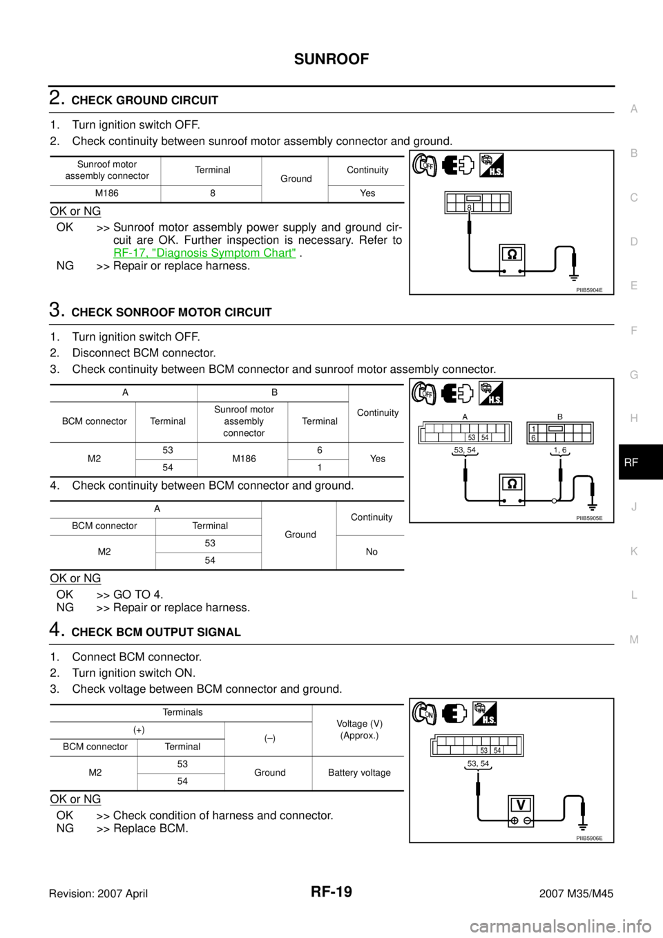
2. CHECK GROUND CIRCUIT
1. Turn ignition switch OFF.
2. Check continuity between sunroof motor assembly connector and ground.
OK or NG
OK >> Sunroof motor assembly power supply and ground cir-
cuit are OK. Further inspection is necessary. Refer to
RF-17, "
Diagnosis Symptom Chart" .
NG >> Repair or replace harness.
3. CHECK SONROOF MOTOR CIRCUIT
1. Turn ignition switch OFF.
2. Disconnect BCM connector.
3. Check continuity between BCM connector and sunroof motor assembly connector.
4. Check continuity between BCM connector and ground.
OK or NG
OK >> GO TO 4.
NG >> Repair or replace harness.
4. CHECK BCM OUTPUT SIGNAL
1. Connect BCM connector.
2. Turn ignition switch ON.
3. Check voltage between BCM connector and ground.
OK or NG
OK >> Check condition of harness and connector.
NG >> Replace BCM.
Sunroof motor
assembly connectorTerminal
GroundContinuity
M186 8 Yes
PIIB5904E
AB
Continuity
BCM connector TerminalSunroof motor
assembly
connectorTerminal
M253
M1866
Ye s
54 1
A
GroundContinuity
BCM connector Terminal
M253
No
54
PIIB5905E
Terminals
Voltage (V)
(Approx.) (+)
(–)
BCM connector Terminal
M253
Ground Battery voltage
54
PIIB5906E
Page 4061 of 4647

RF-20
SUNROOF
Revision: 2007 April2007 M35/M45
Check Sunroof Switch NIS00240
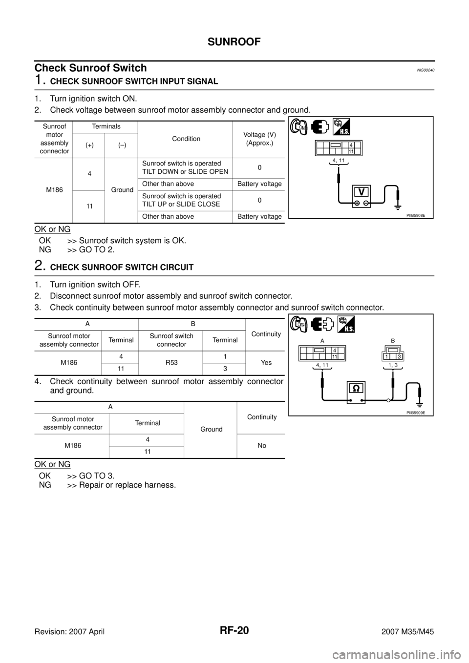
1. CHECK SUNROOF SWITCH INPUT SIGNAL
1. Turn ignition switch ON.
2. Check voltage between sunroof motor assembly connector and ground.
OK or NG
OK >> Sunroof switch system is OK.
NG >> GO TO 2.
2. CHECK SUNROOF SWITCH CIRCUIT
1. Turn ignition switch OFF.
2. Disconnect sunroof motor assembly and sunroof switch connector.
3. Check continuity between sunroof motor assembly connector and sunroof switch connector.
4. Check continuity between sunroof motor assembly connector
and ground.
OK or NG
OK >> GO TO 3.
NG >> Repair or replace harness.
Sunroof
motor
assembly
connectorTerminals
ConditionVoltage (V)
(Approx.)
(+) (–)
M1864
GroundSunroof switch is operated
TILT DOWN or SLIDE OPEN0
Other than above Battery voltage
11Sunroof switch is operated
TILT UP or SLIDE CLOSE0
Other than above Battery voltage
PIIB5908E
AB
Continuity
Sunroof motor
assembly connectorTerminalSunroof switch
connectorTerminal
M1864
R531
Ye s
11 3
A
GroundContinuity
Sunroof motor
assembly connectorTerminal
M1864
No
11
PIIB5909E
Page 4062 of 4647
SUNROOF
RF-21
C
D
E
F
G
H
J
K
L
MA
B
RF
Revision: 2007 April2007 M35/M45
3. CHECK SUNROOF SWITCH GROUND CIRCUIT
Check continuity between sunroof switch connector and ground.
OK or NG
OK >> GO TO 4.
NG >> Repair or replace harness.
4. CHECK SUNROOF SWITCH GROUND CIRCUIT
Check continuity between sunroof motor connector and sunroof switch connector.
OK or NG
OK >> GO TO 5.
NG >> Repair or replace harness.
5. CHECK SUNROOF SWITCH
Check continuity between sunroof switch terminals.
OK or NG
OK >> Replace sunroof motor assembly.
NG >> Replace sunroof switch.
Sunroof switch
connectorTerminal
GroundContinuity
R53 2 Yes
PIIB5910E
AB
Continuity
Sunroof switch
connectorTerminalSunroof motor
assembly connectorTerminal
R53 2 M186 9 Yes
PIIB5911E
Terminals Condition Continuity
1
2Sunroof switch is operated
TILT DOWN or SLIDE OPENYe s
Other than above No
3Sunroof switch is operated
TILT UP or SLIDE CLOSEYe s
Other than above No
PIIB5907E
Page 4063 of 4647
RF-22
SUNROOF
Revision: 2007 April2007 M35/M45
Check Door SwitchNIS00241
1. CHECK DOOR SWITCH INPUT SIGNAL
Check voltage between BCM connector and ground.
OK or NG
OK >> Door switch circuit is OK.
NG >> GO TO 2.
2. CHECK DOOR SWITCH CIRCUIT
1. Turn ignition switch OFF.
2. Disconnect door switch and BCM connector.
3. Check continuity between BCM connector and door switch connector.
4. Check continuity between BCM connector and ground.
OK or NG
OK >> GO TO 3.
NG >> Repair or replace harness.
BCM
connectorItemTerminals
ConditionVoltage (V)
(Approx.)
(+) (–)
M1 Passenger side 12
GroundOPEN 0
CLOSE Battery voltage
M3 Driver side 62OPEN 0
CLOSE Battery voltage
PIIB5912E
AB
Continuity
BCM connector TerminalDriver side door
switch connectorTerminal
M3 62 B11 2 Yes
AC
Continuity
BCM connector TerminalPassenger side
door switch
connectorTerminal
M1 12 B424 2 Yes
A
GroundContinuity
BCM
connectorItem Terminal
M3 Driver side 62
No
M1Passenger
side12
PIIB6494E
Page 4064 of 4647
SUNROOF
RF-23
C
D
E
F
G
H
J
K
L
MA
B
RF
Revision: 2007 April2007 M35/M45
3. CHECK DOOR SWITCH
Check continuity between door switches and ground part of door switch.
OK or NG
OK >> GO TO 4.
NG >> Replace malfunction door switch.
4. CHECK BCM OUTPUT SIGNAL
1. Connect BCM connector.
2. Check voltage between BCM connector and ground.
OK or NG
OK >> Check the condition of the harness and the connector.
NG >> Replace BCM.
Terminal Door switch Continuity
2Ground part of
door switchPushed No
Released Yes
PIIB5914E
Terminals
Voltage (V)
(Approx.) (+)
(-)
BCM
connectorItem Terminal
M3 Driver side 62
Ground Battery voltage
M1 Passenger side 12
PIIB5915E
Page 4065 of 4647

RF-24
SUNROOF
Revision: 2007 April2007 M35/M45
Fitting AdjustmentNIS00242
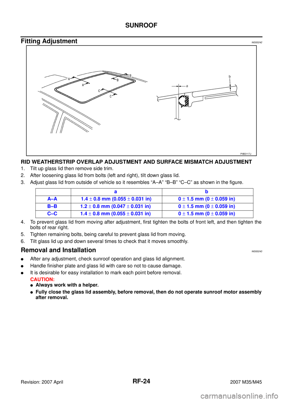
RID WEATHERSTRIP OVERLAP ADJUSTMENT AND SURFACE MISMATCH ADJUSTMENT
1. Tilt up glass lid then remove side trim.
2. After loosening glass lid from bolts (left and right), tilt down glass lid.
3. Adjust glass lid from outside of vehicle so it resembles “A–A” “B–B” “C–C” as shown in the figure.
4. To prevent glass lid from moving after adjustment, first tighten the bolts of front left, and then tighten the
bolts of rear right.
5. Tighten remaining bolts, being careful to prevent glass lid from moving.
6. Tilt glass lid up and down several times to check that it moves smoothly.
Removal and InstallationNIS00243
�After any adjustment, check sunroof operation and glass lid alignment.
�Handle finisher plate and glass lid with care so not to cause damage.
�It is desirable for easy installation to mark each point before removal.
CAUTION:
�Always work with a helper.
�Fully close the glass lid assembly, before removal, then do not operate sunroof motor assembly
after removal.
PIIB3117J
ab
A–A 1.4 ± 0.8 mm (0.055 ± 0.031 in) 0 ± 1.5 mm (0 ± 0.059 in)
B–B 1.2 ± 0.8 mm (0.047 ± 0.031 in) 0 ± 1.5 mm (0 ± 0.059 in)
C–C 1.4 ± 0.8 mm (0.055 ± 0.031 in) 0 ± 1.5 mm (0 ± 0.059 in)
Page 4066 of 4647
SUNROOF
RF-25
C
D
E
F
G
H
J
K
L
MA
B
RF
Revision: 2007 April2007 M35/M45
1. Drain hose 2. Side trim (LH/RH) 3. Glass lid
PIIB3115E