Page 1355 of 4647
![INFINITI M35 2007 Factory Service Manual BRC-54
[VDC/TCS/ABS]
WHEEL SENSOR
Revision: 2007 April2007 M35/M45
WHEEL SENSORPFP:47910
Removal and InstallationNFS000RA
COMPONENT
NOTE:
The above figure (front side) shows left side. Right side is t](/manual-img/42/57024/w960_57024-1354.png "INFINITI M35 2007 Factory Service Manual BRC-54
[VDC/TCS/ABS]
WHEEL SENSOR
Revision: 2007 April2007 M35/M45
WHEEL SENSORPFP:47910
Removal and InstallationNFS000RA
COMPONENT
NOTE:
The above figure (front side) shows left side. Right side is t")
BRC-54
[VDC/TCS/ABS]
WHEEL SENSOR
Revision: 2007 April2007 M35/M45
WHEEL SENSORPFP:47910
Removal and InstallationNFS000RA
COMPONENT
NOTE:
The above figure (front side) shows left side. Right side is the mirror image.
REMOVAL
Pay attention to the following when removing sensor.
CAUTION:
�Do not twist sensor harness as much as possible, when removing it. Pull sensors out without pull-
ing on sensor harness.
�Take care to avoid damaging sensor edges or rotor teeth. Remove wheel sensor first before
removing front or rear wheel hub. This is to avoid damage to sensor wiring and loss of sensor
function.
INSTALLATION
Pay attention to the following when installing wheel sensor. Tighten installation bolts to the specified torques.
Refer to BRC-54, "
COMPONENT" .
1. Front LH wheel sensor 2. Front LH wheel sensor connector 3. Clamp
4. Bracket 5. Rear RH wheel sensor connector 6. Rear LH wheel sensor connector
7. Rear LH wheel sensor 8. Rear RH wheel sensor
A. Front side B. Rear side : Front
Refer to GI section GI-11, "
Components" for symbol marks in the figure.
SFIA2723J
Page 1356 of 4647
WHEEL SENSOR
BRC-55
[VDC/TCS/ABS]
C
D
E
G
H
I
J
K
L
MA
B
BRC
Revision: 2007 April2007 M35/M45
�When installing, make sure there is no foreign material such as iron chips on and in the mounting hole of
the wheel sensor. Make sure no foreign material has been caught in the sensor rotor. Remove any foreign
material and clean the mount.
�When installing wheel sensor, be sure to press rubber grommets in until they lock at locations shown
above in the figure. When installed, harness must not be twisted.
Page 1357 of 4647
BRC-56
[VDC/TCS/ABS]
SENSOR ROTOR
Revision: 2007 April2007 M35/M45
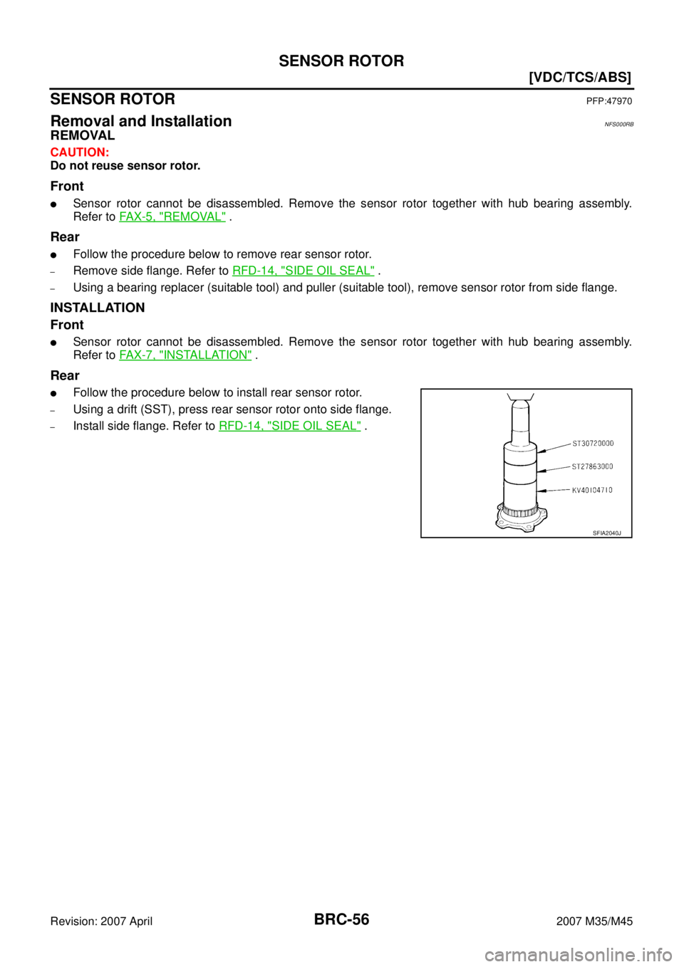
SENSOR ROTORPFP:47970
Removal and InstallationNFS000RB
REMOVAL
CAUTION:
Do not reuse sensor rotor.
Front
�Sensor rotor cannot be disassembled. Remove the sensor rotor together with hub bearing assembly.
Refer to FAX-5, "
REMOVAL" .
Rear
�Follow the procedure below to remove rear sensor rotor.
–Remove side flange. Refer to RFD-14, "SIDE OIL SEAL" .
–Using a bearing replacer (suitable tool) and puller (suitable tool), remove sensor rotor from side flange.
INSTALLATION
Front
�Sensor rotor cannot be disassembled. Remove the sensor rotor together with hub bearing assembly.
Refer to FAX-7, "
INSTALLATION" .
Rear
�Follow the procedure below to install rear sensor rotor.
–Using a drift (SST), press rear sensor rotor onto side flange.
–Install side flange. Refer to RFD-14, "SIDE OIL SEAL" .
SFIA2040J
Page 1359 of 4647
BRC-58
[VDC/TCS/ABS]
ACTUATOR AND ELECTRIC UNIT (ASSEMBLY)
Revision: 2007 April2007 M35/M45
7. Remove ABS actuator and electric unit (control unit) from vehicle.
INSTALLATION
Installation is the reverse order of removal.
CAUTION:
When replacing ABS actuator and electric unit (control unit), make sure to adjust neutral position of
steering angle sensor. Refer to BRC-6, "
Adjustment of Steering Angle Sensor Neutral Position"
Page 1360 of 4647
G-SENSOR
BRC-59
[VDC/TCS/ABS]
C
D
E
G
H
I
J
K
L
MA
B
BRC
Revision: 2007 April2007 M35/M45
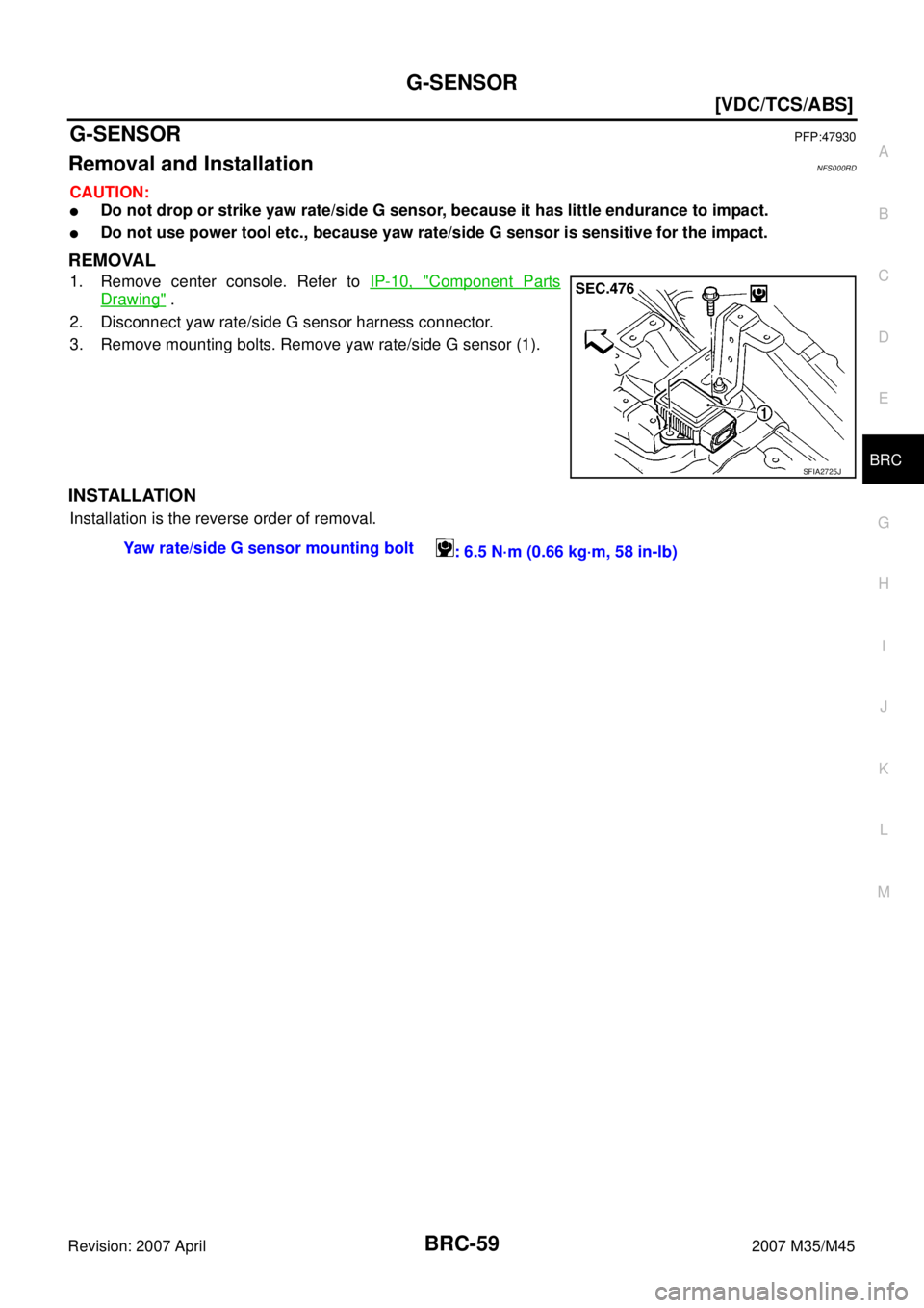
G-SENSORPFP:47930
Removal and InstallationNFS000RD
CAUTION:
�Do not drop or strike yaw rate/side G sensor, because it has little endurance to impact.
�Do not use power tool etc., because yaw rate/side G sensor is sensitive for the impact.
REMOVAL
1. Remove center console. Refer to IP-10, "Component Parts
Drawing" .
2. Disconnect yaw rate/side G sensor harness connector.
3. Remove mounting bolts. Remove yaw rate/side G sensor (1).
INSTALLATION
Installation is the reverse order of removal.
SFIA2725J
Yaw rate/side G sensor mounting bolt
: 6.5 N·m (0.66 kg·m, 58 in-lb)
Page 1361 of 4647
BRC-60
[VDC/TCS/ABS]
STEERING ANGLE SENSOR
Revision: 2007 April2007 M35/M45
STEERING ANGLE SENSORPFP:25554
Removal and InstallationNFS000RE
REMOVAL
1. Remove spiral cable assembly. Refer to SRS-44, "SPIRAL CABLE" .
2. Remove steering angle sensor from spiral cable assembly.
INSTALLATION
Installation is the reverse order of removal.
CAUTION:
After work, make sure to adjust neutral position of steering angle sensor. Refer to BRC-6, "
Adjustment
of Steering Angle Sensor Neutral Position" .
SFIA1404E
Page 1392 of 4647
![INFINITI M35 2007 Factory Service Manual WATER OUTLET AND WATER PIPING
CO-31
[VQ35DE]
C
D
E
F
G
H
I
J
K
L
MA
CO
Revision: 2007 April2007 M35/M45
WATER OUTLET AND WATER PIPINGPFP:11060
ComponentsNBS004R5
Removal and InstallationNBS004R6
REMOV](/manual-img/42/57024/w960_57024-1391.png "INFINITI M35 2007 Factory Service Manual WATER OUTLET AND WATER PIPING
CO-31
[VQ35DE]
C
D
E
F
G
H
I
J
K
L
MA
CO
Revision: 2007 April2007 M35/M45
WATER OUTLET AND WATER PIPINGPFP:11060
ComponentsNBS004R5
Removal and InstallationNBS004R6
REMOV")
WATER OUTLET AND WATER PIPING
CO-31
[VQ35DE]
C
D
E
F
G
H
I
J
K
L
MA
CO
Revision: 2007 April2007 M35/M45
WATER OUTLET AND WATER PIPINGPFP:11060
ComponentsNBS004R5
Removal and InstallationNBS004R6
REMOVAL
1. Remove engine room cover (RH and LH). Refer to EM-15, "ENGINE ROOM COVER" .
2. Remove engine cover with power tool. Refer to EM-21, "
INTAKE MANIFOLD COLLECTOR" .
3. Remove air duct (inlet) and air cleaner case assembly. Refer to EM-19, "
AIR CLEANER AND AIR DUCT"
.
4. Remove front engine undercover with power tool.
5. Drain engine coolant from radiator drain plug at the bottom of radiator, and from water drain plug at the
front of cylinder block. Refer to CO-11, "
Changing Engine Coolant" and CO-24, "WATER PUMP" .
CAUTION:
�Perform this step when the engine is cold.
�Do not spill engine coolant on drive belts.
6. Remove radiator hose (upper) and heater hose.
7. Remove the following parts, when remove water outlet.
�A/T fluid charging pipe: Refer to AT- 2 7 4 , "TRANSMISSION ASSEMBLY" .
�Intake manifold collectors (upper and lower): Refer to EM-21, "INTAKE MANIFOLD COLLECTOR" .
�Rocker cover (right bank): Refer to EM-53, "ROCKER COVER" .
8. Remove engine coolant temperature sensor as necessary.
CAUTION:
Be careful not to damage engine coolant temperature sensor.
1. Harness bracket 2. Water hose 3. Water bypass hose
4. Engine coolant temperature sensor 5. Gasket 6. Water outlet
7. Heater hose 8. Water pipe 9. Radiator hose (upper)
10. Heater pipe 11. Washer 12. O-ring
SBIA0484E
Page 1420 of 4647

DI-1
DRIVER INFORMATION SYSTEM
K ELECTRICAL
CONTENTS
C
D
E
F
G
H
I
J
L
M
SECTION DI
A
B
DI
Revision: 2007 April2007 M35/M45
DRIVER INFORMATION SYSTEM
PRECAUTION ............................................................ 3
Precautions for Supplemental Restraint System
(SRS) “AIR BAG” and “SEAT BELT PRE-TEN-
SIONER” .................................................................. 3
PREPARATION ........................................................... 4
Commercial Service Tools ........................................ 4
COMBINATION METERS ........................................... 5
System Description .................................................. 5
UNIFIED METER CONTROL UNIT ...................... 5
UNIFIED METER AND A/C AMP. ......................... 5
POWER SUPPLY AND GROUND CIRCUIT ........ 5
SPEEDOMETER ................................................... 6
TACHOMETER ..................................................... 6
WATER TEMPERATURE GAUGE ........................ 6
FUEL GAUGE ....................................................... 7
ODO/TRIP METER ............................................... 7
METER ILLUMINATION CONTROL ..................... 8
FAIL-SAFE ............................................................ 9
Arrangement of Combination Meter ....................... 10
Component Parts Location ...................................... 11
Internal Circuit ........................................................ 12
Wiring Diagram — METER — ................................ 13
Terminals and Reference Value for Combination
Meter ...................................................................... 15
Terminals and Reference Value for Unified Meter
and A/C Amp. ......................................................... 16
Self-Diagnosis Mode of Combination Meter ........... 17
SELF-DIAGNOSIS FUNCTION .......................... 17
OPERATION PROCEDURE ............................... 17
CONSULT-II Function (METER A/C AMP) ............. 18
Trouble Diagnosis .................................................. 18
HOW TO PERFORM TROUBLE DIAGNOSIS ... 18
PRELIMINARY CHECK ...................................... 18
Symptom Chart ...................................................... 18
Power Supply and Ground Circuit Inspection ........ 19
Vehicle Speed Signal Inspection ............................ 20
Engine Speed Signal Inspection ............................ 21
Engine Coolant Temperature Signal Inspection ..... 22
Fuel Level Sensor Signal Inspection ...................... 22
Fuel Gauge Pointer Fluctuates, Indicator Wrong Value or Varies ....................................................... 25
Fuel Gauge Does Not Move to FULL Position ....... 25
Electrical Components Inspection .......................... 26
CHECK FUEL LEVEL SENSOR UNIT ................ 26
Removal and Installation of Combination Meter ..... 27
REMOVAL ........................................................... 27
INSTALLATION ................................................... 27
Disassembly and Assembly of Combination Meter ... 27
DISASSEMBLY ................................................... 27
ASSEMBLY ......................................................... 27
UNIFIED METER AND A/C AMP .............................. 28
System Description ................................................. 28
COMBINATION METER CONTROL FUNCTION ... 28
A/C AUTO AMP. FUNCTION ............................... 29
OTHER FUNCTIONS .......................................... 29
Schematic ............................................................... 30
CONSULT-II Function (METER A/C AMP) ............. 31
CONSULT-II BASIC OPERATION ....................... 31
SELF-DIAG RESULTS ........................................ 31
DATA MONITOR ................................................. 32
Power Supply and Ground Circuit Inspection ......... 34
DTC [U1000] CAN Communication Circuit ............. 35
DTC [B2202] Meter Communication Circuit ........... 35
DTC [B2205] Vehicle Speed Circuit ........................ 38
Removal and Installation of Unified Meter and A/C
Amp. ....................................................................... 38
REMOVAL ........................................................... 38
INSTALLATION ................................................... 38
WARNING LAMPS .................................................... 39
System Description ................................................. 39
OIL PRESSURE WARNING LAMP ..................... 39
Component Parts and Harness Connector Location ... 40
Schematic ............................................................... 41
Wiring Diagram — WARN — .................................. 42
Oil Pressure Warning Lamp Stays Off (Ignition
Switch ON) ............................................................. 52
Oil Pressure Warning Lamp Does Not Turn Off (Oil
Pressure Is Normal) ................................................ 53
Electrical Component Inspection ............................ 54
OIL PRESSURE SWITCH ................................... 54

![INFINITI M35 2007 Factory Service Manual BRC-58
[VDC/TCS/ABS]
ACTUATOR AND ELECTRIC UNIT (ASSEMBLY)
Revision: 2007 April2007 M35/M45
7. Remove ABS actuator and electric unit (control unit) from vehicle.
INSTALLATION
Installation is the rever](/manual-img/42/57024/w960_57024-1358.png "INFINITI M35 2007 Factory Service Manual BRC-58
[VDC/TCS/ABS]
ACTUATOR AND ELECTRIC UNIT (ASSEMBLY)
Revision: 2007 April2007 M35/M45
7. Remove ABS actuator and electric unit (control unit) from vehicle.
INSTALLATION
Installation is the rever")
![INFINITI M35 2007 Factory Service Manual BRC-60
[VDC/TCS/ABS]
STEERING ANGLE SENSOR
Revision: 2007 April2007 M35/M45
STEERING ANGLE SENSORPFP:25554
Removal and InstallationNFS000RE
REMOVAL
1. Remove spiral cable assembly. Refer to SRS-44, "S](/manual-img/42/57024/w960_57024-1360.png "INFINITI M35 2007 Factory Service Manual BRC-60
[VDC/TCS/ABS]
STEERING ANGLE SENSOR
Revision: 2007 April2007 M35/M45
STEERING ANGLE SENSORPFP:25554
Removal and InstallationNFS000RE
REMOVAL
1. Remove spiral cable assembly. Refer to SRS-44, \"S")