Page 3869 of 4647

PG-18
IPDM E/R (INTELLIGENT POWER DISTRIBUTION MODULE ENGINE ROOM)
Revision: 2007 April2007 M35/M45
IPDM E/R (INTELLIGENT POWER DISTRIBUTION MODULE ENGINE ROOM)
PFP:284B7
System DescriptionNKS004E2
�IPDM E/R (Intelligent Power Distribution Module Engine Room) integrates the relay box and fuse block
which were originally placed in engine compartment. It controls integrated relay via IPDM E/R control cir-
cuit.
�IPDM E/R-integrated control circuit performs ON-OFF operation of relay, CAN communication control and
oil pressure switch signal reception, etc.
�It controls operation of each electrical part via ECM, BCM and CAN communication lines.
CAUTION:
None of the IPDM E/R-integrated relays can be removed.
SYSTEMS CONTROLLED BY IPDM E/R
1. Lamp control
Using CAN communication, it receives signal from BCM and controls the following lamps:
�Headlamps (HI, LO)
�Tail, parking and license plate lamps
�Front fog lamps
2. Daytime light relay control (for Canada models)
Using CAN communication, it receives signals from BCM and controls the daytime light relay.
3. Wiper control
Using CAN communication, it receives signals from BCM and controls the front wipers.
4. Rear window defogger relay control
Using CAN communication, it receives signals from BCM and controls the rear window defogger relay.
5. A/C compressor control
Using CAN communication, it receives signals from ECM and controls the A/C relay.
6. Cooling fan control
Using CAN communication, it receives signals from ECM and controls cooling fan via cooling fan control
module.
7. Horn control
Using CAN communication, it receives signals from BCM and controls horn relay.
8. Starter motor relay control
Using CAN communication, it receives signals from BCM and controls starter motor relay.
9. Alternator control
Using CAN communication, it receives signal from ECM and controls power generation voltage.
CAN COMMUNICATION LINE CONTROL
With CAN communication, by connecting each control unit using two communication lines (CAN L-line, CAN
H-line), it is possible to transmit maximum amount of information with minimum wiring. Each control unit can
transmit and receive data, and reads necessary information only.
1. Fail-safe control
�When CAN communication with other control units is impossible, IPDM E/R performs fail-safe control.
After CAN communication recovers normally, it also returns to normal control.
�Operation of control parts by IPDM E/R during fail-safe mode is as follows:
Controlled system Fail-safe mode
Headlamps
�With the ignition switch ON, the headlamp low relay is ON.
�With the ignition switch OFF, the headlamp low relay is OFF.
Tail, parking and
license plate lamps
�With the ignition switch ON, the tail lamp relay is ON.
�With the ignition switch OFF, the tail lamp relay is OFF.
Cooling fan
�With the ignition switch ON, the cooling fan HI operates.
�With the ignition switch OFF, the cooling fan stops.
Front wiperUntil the ignition switch is turned off, the front wiper LO and HI remains in the same status it was in just
before fail−safe control was initiated.
Page 3883 of 4647

PG-32
PDU (POWER DISTRIBUTION UNIT)
Revision: 2007 April2007 M35/M45
PDU (POWER DISTRIBUTION UNIT)PFP:285F1
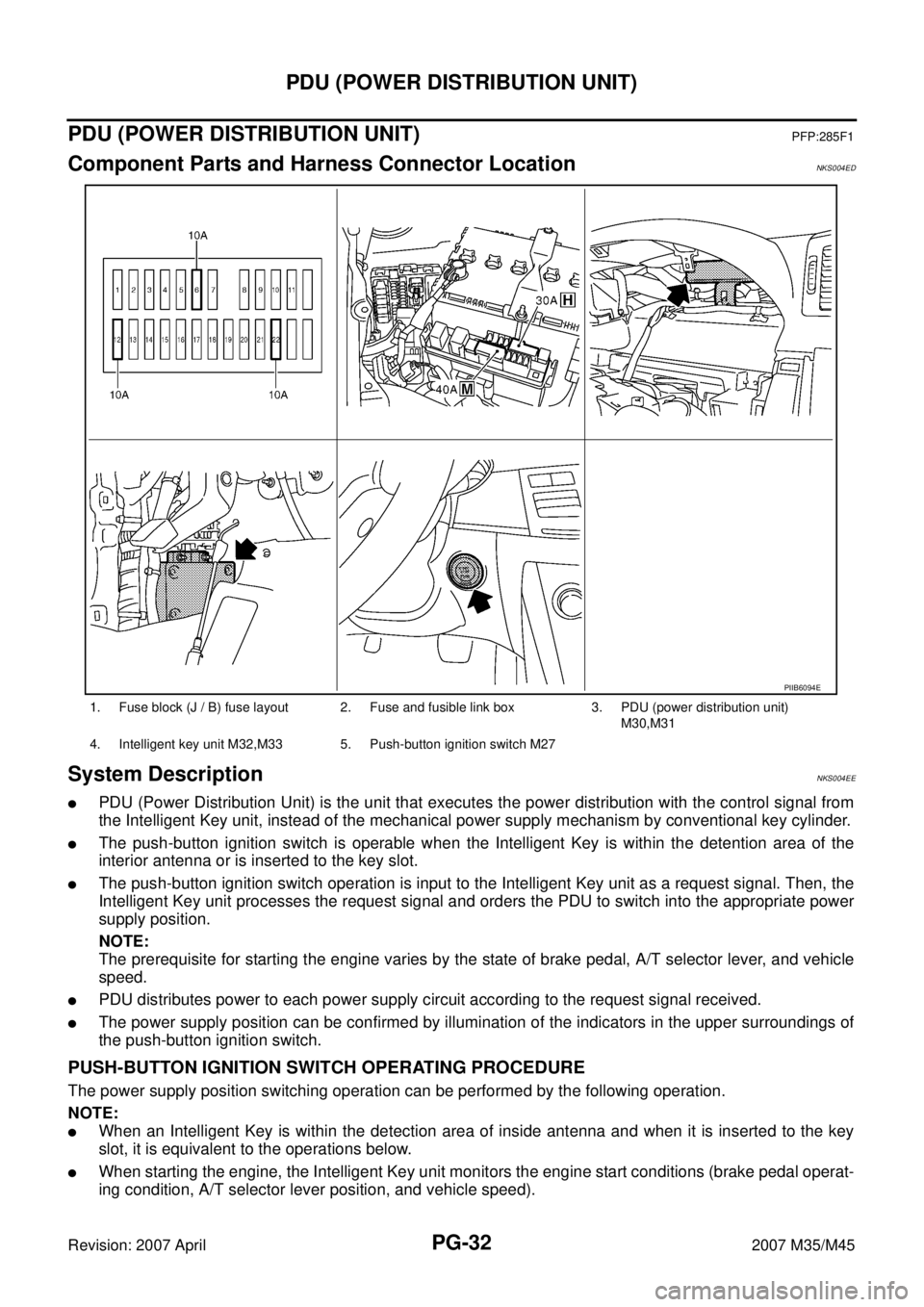
Component Parts and Harness Connector LocationNKS004ED
System DescriptionNKS004EE
�PDU (Power Distribution Unit) is the unit that executes the power distribution with the control signal from
the Intelligent Key unit, instead of the mechanical power supply mechanism by conventional key cylinder.
�The push-button ignition switch is operable when the Intelligent Key is within the detention area of the
interior antenna or is inserted to the key slot.
�The push-button ignition switch operation is input to the Intelligent Key unit as a request signal. Then, the
Intelligent Key unit processes the request signal and orders the PDU to switch into the appropriate power
supply position.
NOTE:
The prerequisite for starting the engine varies by the state of brake pedal, A/T selector lever, and vehicle
speed.
�PDU distributes power to each power supply circuit according to the request signal received.
�The power supply position can be confirmed by illumination of the indicators in the upper surroundings of
the push-button ignition switch.
PUSH-BUTTON IGNITION SWITCH OPERATING PROCEDURE
The power supply position switching operation can be performed by the following operation.
NOTE:
�When an Intelligent Key is within the detection area of inside antenna and when it is inserted to the key
slot, it is equivalent to the operations below.
�When starting the engine, the Intelligent Key unit monitors the engine start conditions (brake pedal operat-
ing condition, A/T selector lever position, and vehicle speed).
1. Fuse block (J / B) fuse layout 2. Fuse and fusible link box 3. PDU (power distribution unit)
M30,M31
4. Intelligent key unit M32,M33 5. Push-button ignition switch M27
PIIB6094E
Page 3965 of 4647
PG-114
FUSE BLOCK - JUNCTION BOX (J/B)
Revision: 2007 April2007 M35/M45
FUSE BLOCK - JUNCTION BOX (J/B)PFP:24350
Terminal ArrangementNKS004EZ
CKIT0663E
Page 3966 of 4647
FUSE, FUSIBLE LINK AND RELAY BOX
PG-115
C
D
E
F
G
H
I
J
L
MA
B
PG
Revision: 2007 April2007 M35/M45
FUSE, FUSIBLE LINK AND RELAY BOXPFP:24382
Terminal ArrangementNKS004F0
CKIT0664E
Page 3967 of 4647
PG-116
FUSE, FUSIBLE LINK AND RELAY BOX
Revision: 2007 April2007 M35/M45
Page 4051 of 4647
RF-10
SUNROOF
Revision: 2007 April2007 M35/M45
SUNROOFPFP:91210
Component Parts and Harness Connector LocationNIS0023Q
PIIB6291E
1. Fuse block (J/B) 2. Fuse and fusible link box 3. BCM M1, M2, M3
(View with the glove box assembly removed)
4. Sunroof motor assembly M186 5. Sunroof switch R53 6. Front door switch driver side B11
Page 4052 of 4647

SUNROOF
RF-11
C
D
E
F
G
H
J
K
L
MA
B
RF
Revision: 2007 April2007 M35/M45
System DescriptionNIS0023R
Power supplied at all time
�through 50A fusible link (letter F , located in the fuse and fusible link box)
�to BCM terminal 55.
�through 10A fuse [No.21, located in the fuse block (J/B)]
�to BCM terminal 42.
�through BCM terminal 54
�to sunroof motor assembly terminal 1.
When ignition switch ON or START position,
Power is supplied
�through 15A fuse [No.1, located in the fuse block (J/B)]
�to BCM terminal 38.
�through BCM terminal 53
�to sunroof motor assembly terminal 6.
Ground is supplied
�to BCM terminal 52
�through body grounds M16 and M70.
�to sunroof motor assembly terminal 8
�through body ground M16 and M70.
TILT UP / SLIDE CLOSE OPERATION
When tilt up / slide close switch is pressed,
Ground is supplied
�to sunroof motor assembly terminal 11
�through sunroof switch terminal 3
�through sunroof switch terminal 2
�through sunroof motor assembly terminal 9.
Then, the sunroof tilt up / slide close.
TILT DOWN / SLIDE OPEN OPERATION
When tilt down / slide open switch is pressed,
Ground is supplied
�to sunroof motor assembly terminal 4
�through sunroof switch terminal 1
�through sunroof switch terminal 2
�through sunroof motor assembly terminal 9.
Then, the sunroof tilt down / slide open.
AUTO OPERATION
The power sunroof AUTO feature makes it possible to slide open and slide close or tilt up and tilt down the
sunroof without holding the sunroof switch in the SLIDE OPEN/TILT DOWN or SLIDE CLOSE/TILT UP posi-
tion.
RETAINED POWER OPERATION
When the ignition switch is turned to OFF position from ON position, power is supplied for 45 seconds.
�through BCM terminal 53.
�to sunroof motor assembly terminal 6.
When power is supplied, the sunroof can be operated.
The retained power operation is canceled when the driver or passenger side door is opened.
RAP signal period can be changed by CONSULT-II. Refer to RF-16, "
CONSULT-II Function (BCM)" .
Page 4058 of 4647

SUNROOF
RF-17
C
D
E
F
G
H
J
K
L
MA
B
RF
Revision: 2007 April2007 M35/M45
Work FlowNIS0023W
1. Check the symptom and customer's requests.
2. Understand the outline of system. Refer to RF-11, "
System Description" .
3. According to the trouble diagnosis chart, repair or replace the cause of the malfunction. Refer to RF-17,
"Diagnosis Symptom Chart" .
4. Does sunroof system operate normally? If Yes, GO TO 5. If No, GO TO 3.
5. INSPECTION END.
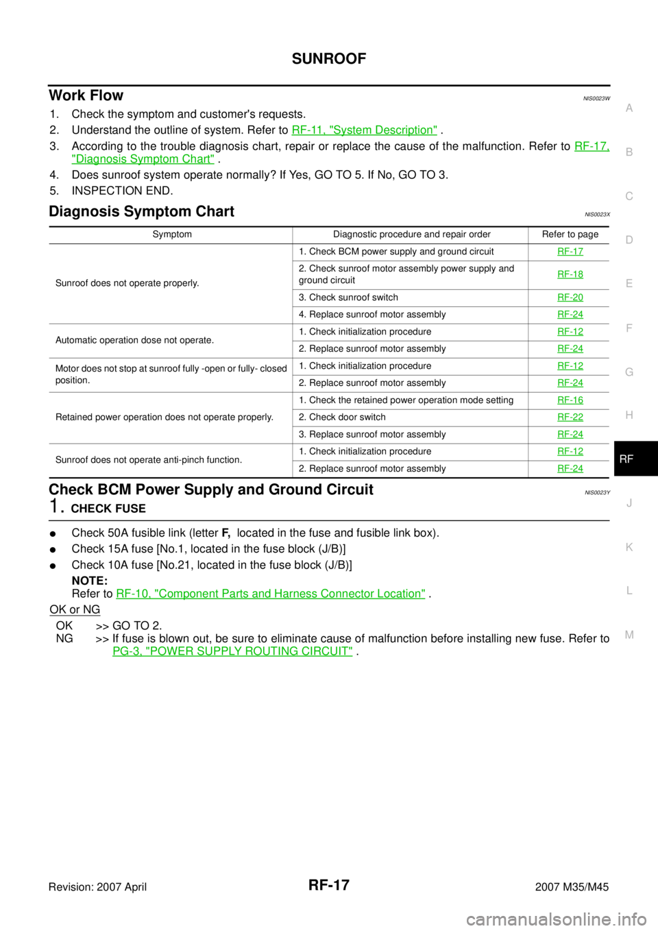
Diagnosis Symptom ChartNIS0023X
Check BCM Power Supply and Ground Circuit NIS0023Y
1. CHECK FUSE
�Check 50A fusible link (letter F, located in the fuse and fusible link box).
�Check 15A fuse [No.1, located in the fuse block (J/B)]
�Check 10A fuse [No.21, located in the fuse block (J/B)]
NOTE:
Refer to RF-10, "
Component Parts and Harness Connector Location" .
OK or NG
OK >> GO TO 2.
NG >> If fuse is blown out, be sure to eliminate cause of malfunction before installing new fuse. Refer to
PG-3, "
POWER SUPPLY ROUTING CIRCUIT" .
Symptom Diagnostic procedure and repair order Refer to page
Sunroof does not operate properly.1. Check BCM power supply and ground circuit RF-17
2. Check sunroof motor assembly power supply and
ground circuit RF-18
3. Check sunroof switchRF-20
4. Replace sunroof motor assemblyRF-24
Automatic operation dose not operate.1. Check initialization procedureRF-122. Replace sunroof motor assemblyRF-24
Motor does not stop at sunroof fully -open or fully- closed
position.1. Check initialization procedureRF-12
2. Replace sunroof motor assemblyRF-24
Retained power operation does not operate properly.1. Check the retained power operation mode settingRF-162. Check door switchRF-22
3. Replace sunroof motor assemblyRF-24
Sunroof does not operate anti-pinch function.1. Check initialization procedureRF-122. Replace sunroof motor assemblyRF-24