Page 4141 of 4647
![INFINITI M35 2007 Factory Service Manual SB-16
PRE-CRASH SEAT BELT
Revision: 2007 April2007 M35/M45
Check Ignition Power Supply Circuit NHS00089
1. CHECK FUSE
Check 10A fuse [No.15, located in fuse block (J/B)].
NOTE:
Refer to SB-3, "
Compon INFINITI M35 2007 Factory Service Manual SB-16
PRE-CRASH SEAT BELT
Revision: 2007 April2007 M35/M45
Check Ignition Power Supply Circuit NHS00089
1. CHECK FUSE
Check 10A fuse [No.15, located in fuse block (J/B)].
NOTE:
Refer to SB-3, "
Compon](/manual-img/42/57024/w960_57024-4140.png)
SB-16
PRE-CRASH SEAT BELT
Revision: 2007 April2007 M35/M45
Check Ignition Power Supply Circuit NHS00089
1. CHECK FUSE
Check 10A fuse [No.15, located in fuse block (J/B)].
NOTE:
Refer to SB-3, "
Component Parts and Harness Connector Location" .
OK or NG
OK >> GO TO 2.
NG >> If fuse is blown out, be sure to eliminate cause of malfunction before installing new fuse. Refer to
PG-3, "
POWER SUPPLY ROUTING CIRCUIT" .
2. CHECK IGNITION POWER SUPPLY CIRCUIT
1. Turn ignition switch OFF.
2. Disconnect pre-crash seat belt control unit connector.
3. Turn ignition switch ON.
4. Check voltage between pre-crash seat belt control unit harness
connector and ground.
OK or NG
OK >> Ignition power supply circuit is OK.
NG >> Check pre-crash seat belt control unit ignition power supply circuit harness.
Check Motor Power Supply and Ground Circuit [B2454]NHS0008A
1. CHECK FUSE
Check 30A fusible link (letter G , located in the fuse and fusible link box).
NOTE:
Refer to SB-3, "
Component Parts and Harness Connector Location" .
OK or NG
OK >> GO TO 2.
NG >> If fuse is blown out, be sure to eliminate cause of malfunction before installing new fuse. Refer to
PG-3, "
POWER SUPPLY ROUTING CIRCUIT" .
Terminal
Voltage (V)
(Approx.) (+)
(–) Pre-crash seat
belt control unit
connectorTerminal
B142 13 Ground Battery voltage
PHIA1126E
Page 4210 of 4647
AUTOMATIC DRIVE POSITIONER
SE-11
C
D
E
F
G
H
J
K
L
MA
B
SE
Revision: 2007 April2007 M35/M45
AUTOMATIC DRIVE POSITIONERPFP:28491
Component Parts And Harness Connector LocationNIS0025Q
PIIB6292E
1. Fuse block (J/B) 2. Fuse and fusible link box 3. BCM M1, M2, M3
(View with the glove box assembly
removed)
4. A. Automatic drive positioner control
unit M6, M7
B. Telescopic motor M45
C. Telescopic sensor M44
D. Tilt sensor M37
E. Tilt motor M36
(View with the driver lower panel
removed)5. A. Front lifting motor B209
B. Rear lifting motor B210
C. Driver seat control unit
B204,B205
D. Sliding motor B2076. Seat memory switch D9
7. A. Lumbar support switch B212
B. Reclining switch B213
C. Sliding/Lifting switch B2138. A. ADP steering switch M46
B. Key slot M14
C. Door mirror control switch M959. Reclining motor B208
Page 4303 of 4647

SE-104
POWER SEAT(REAR)
Revision: 2007 April2007 M35/M45
Work FlowNIS00277
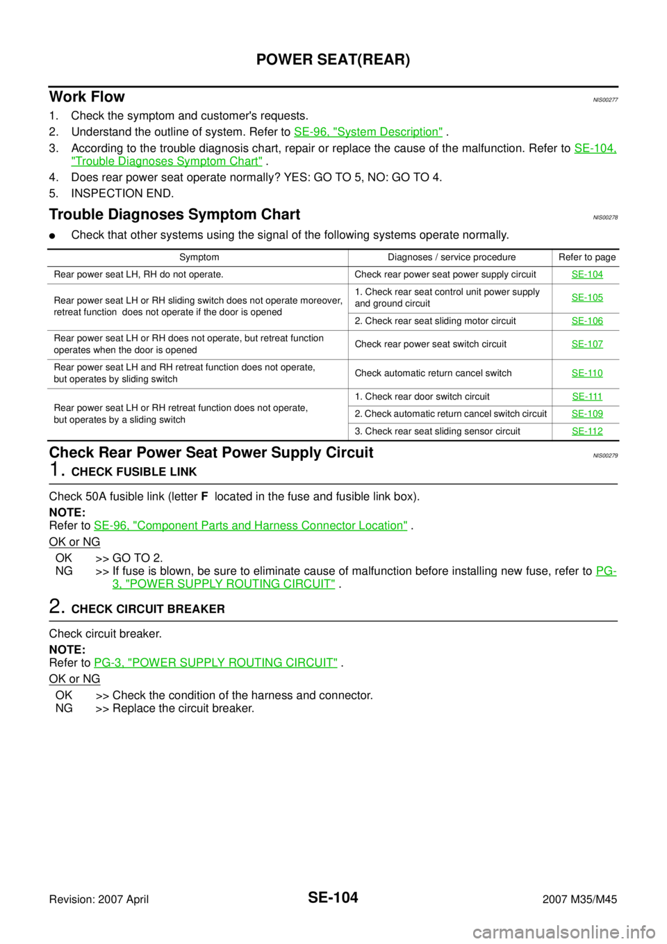
1. Check the symptom and customer's requests.
2. Understand the outline of system. Refer to SE-96, "
System Description" .
3. According to the trouble diagnosis chart, repair or replace the cause of the malfunction. Refer to SE-104,
"Trouble Diagnoses Symptom Chart" .
4. Does rear power seat operate normally? YES: GO TO 5, NO: GO TO 4.
5. INSPECTION END.
Trouble Diagnoses Symptom ChartNIS00278
�Check that other systems using the signal of the following systems operate normally.
Check Rear Power Seat Power Supply CircuitNIS00279
1. CHECK FUSIBLE LINK
Check 50A fusible link (letter F located in the fuse and fusible link box).
NOTE:
Refer to SE-96, "
Component Parts and Harness Connector Location" .
OK or NG
OK >> GO TO 2.
NG >> If fuse is blown, be sure to eliminate cause of malfunction before installing new fuse, refer to PG-
3, "POWER SUPPLY ROUTING CIRCUIT" .
2. CHECK CIRCUIT BREAKER
Check circuit breaker.
NOTE:
Refer to PG-3, "
POWER SUPPLY ROUTING CIRCUIT" .
OK or NG
OK >> Check the condition of the harness and connector.
NG >> Replace the circuit breaker.
Symptom Diagnoses / service procedure Refer to page
Rear power seat LH, RH do not operate. Check rear power seat power supply circuitSE-104
Rear power seat LH or RH sliding switch does not operate moreover,
retreat function does not operate if the door is opened1. Check rear seat control unit power supply
and ground circuit SE-105
2. Check rear seat sliding motor circuit SE-106
Rear power seat LH or RH does not operate, but retreat function
operates when the door is openedCheck rear power seat switch circuitSE-107
Rear power seat LH and RH retreat function does not operate,
but operates by sliding switchCheck automatic return cancel switchSE-110
Rear power seat LH or RH retreat function does not operate,
but operates by a sliding switch1. Check rear door switch circuitSE-1112. Check automatic return cancel switch circuit SE-109
3. Check rear seat sliding sensor circuitSE-112
Page 4352 of 4647

HEATED SEAT
SE-153
C
D
E
F
G
H
J
K
L
MA
B
SE
Revision: 2007 April2007 M35/M45
Check Rear Heated Seat Power Supply and Ground CircuitNIS00287
1. CHECK FUSIBLE LINK AND FUSE
�Check 50A fusible link (letter F located in the fuse and fusible link box).
�Check 15A fuse (No.38, located in fuse block).
�Check circuit breaker.
NOTE:
Refer to SE-144, "
Component Parts and Harness Connector Location" .
OK or NG
OK >> GO TO 2.
NG >> If fuse or circuit breaker is blown, be sure to eliminate cause of malfunction before installing new
fuse or new circuit breaker, refer to PG-3, "
POWER SUPPLY ROUTING CIRCUIT" .
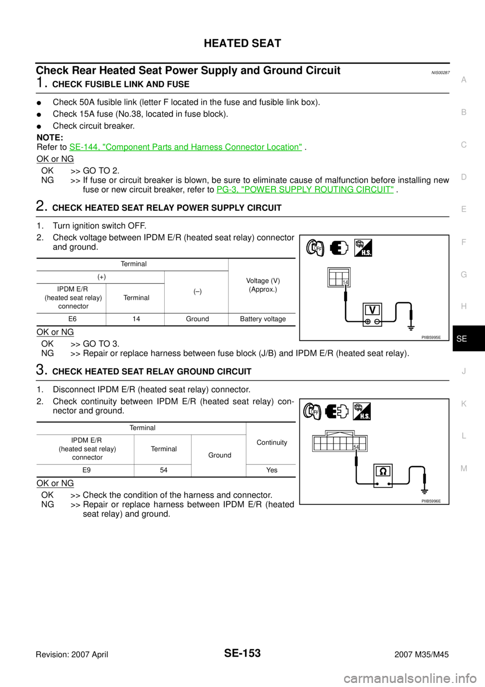
2. CHECK HEATED SEAT RELAY POWER SUPPLY CIRCUIT
1. Turn ignition switch OFF.
2. Check voltage between IPDM E/R (heated seat relay) connector
and ground.
OK or NG
OK >> GO TO 3.
NG >> Repair or replace harness between fuse block (J/B) and IPDM E/R (heated seat relay).
3. CHECK HEATED SEAT RELAY GROUND CIRCUIT
1. Disconnect IPDM E/R (heated seat relay) connector.
2. Check continuity between IPDM E/R (heated seat relay) con-
nector and ground.
OK or NG
OK >> Check the condition of the harness and connector.
NG >> Repair or replace harness between IPDM E/R (heated
seat relay) and ground.
Terminal
Voltage (V)
(Approx.) (+)
(–) IPDM E/R
(heated seat relay)
connectorTerminal
E6 14 Ground Battery voltage
PIIB5995E
Terminal
Continuity IPDM E/R
(heated seat relay)
connectorTerminal
Ground
E9 54 Yes
PIIB5996E
Page 4595 of 4647

WW-4
FRONT WIPER AND WASHER SYSTEM
Revision: 2007 April2007 M35/M45
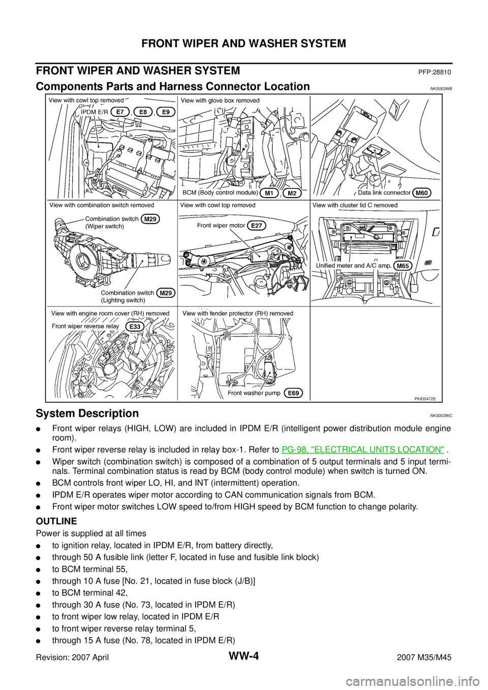
FRONT WIPER AND WASHER SYSTEMPFP:28810
Components Parts and Harness Connector LocationNKS003WB
System DescriptionNKS003WC
�Front wiper relays (HIGH, LOW) are included in IPDM E/R (intelligent power distribution module engine
room).
�Front wiper reverse relay is included in relay box-1. Refer to PG-98, "ELECTRICAL UNITS LOCATION" .
�Wiper switch (combination switch) is composed of a combination of 5 output terminals and 5 input termi-
nals. Terminal combination status is read by BCM (body control module) when switch is turned ON.
�BCM controls front wiper LO, HI, and INT (intermittent) operation.
�IPDM E/R operates wiper motor according to CAN communication signals from BCM.
�Front wiper motor switches LOW speed to/from HIGH speed by BCM function to change polarity.
OUTLINE
Power is supplied at all times
�to ignition relay, located in IPDM E/R, from battery directly,
�through 50 A fusible link (letter F, located in fuse and fusible link block)
�to BCM terminal 55,
�through 10 A fuse [No. 21, located in fuse block (J/B)]
�to BCM terminal 42,
�through 30 A fuse (No. 73, located in IPDM E/R)
�to front wiper low relay, located in IPDM E/R
�to front wiper reverse relay terminal 5,
�through 15 A fuse (No. 78, located in IPDM E/R)
PKID0472E