Page 1471 of 4647

DI-52
WARNING LAMPS
Revision: 2007 April2007 M35/M45
Oil Pressure Warning Lamp Stays Off (Ignition Switch ON)NKS003US
1. CHECK OPERATION OF OIL PRESSURE WARNING LAMP
Activate IPDM E/R auto active test. Refer to PG-23, "
Auto Active Test" .
Does oil pressure warning lamp is blinking?
YES >> GO TO 2.
NO >> GO TO 4.
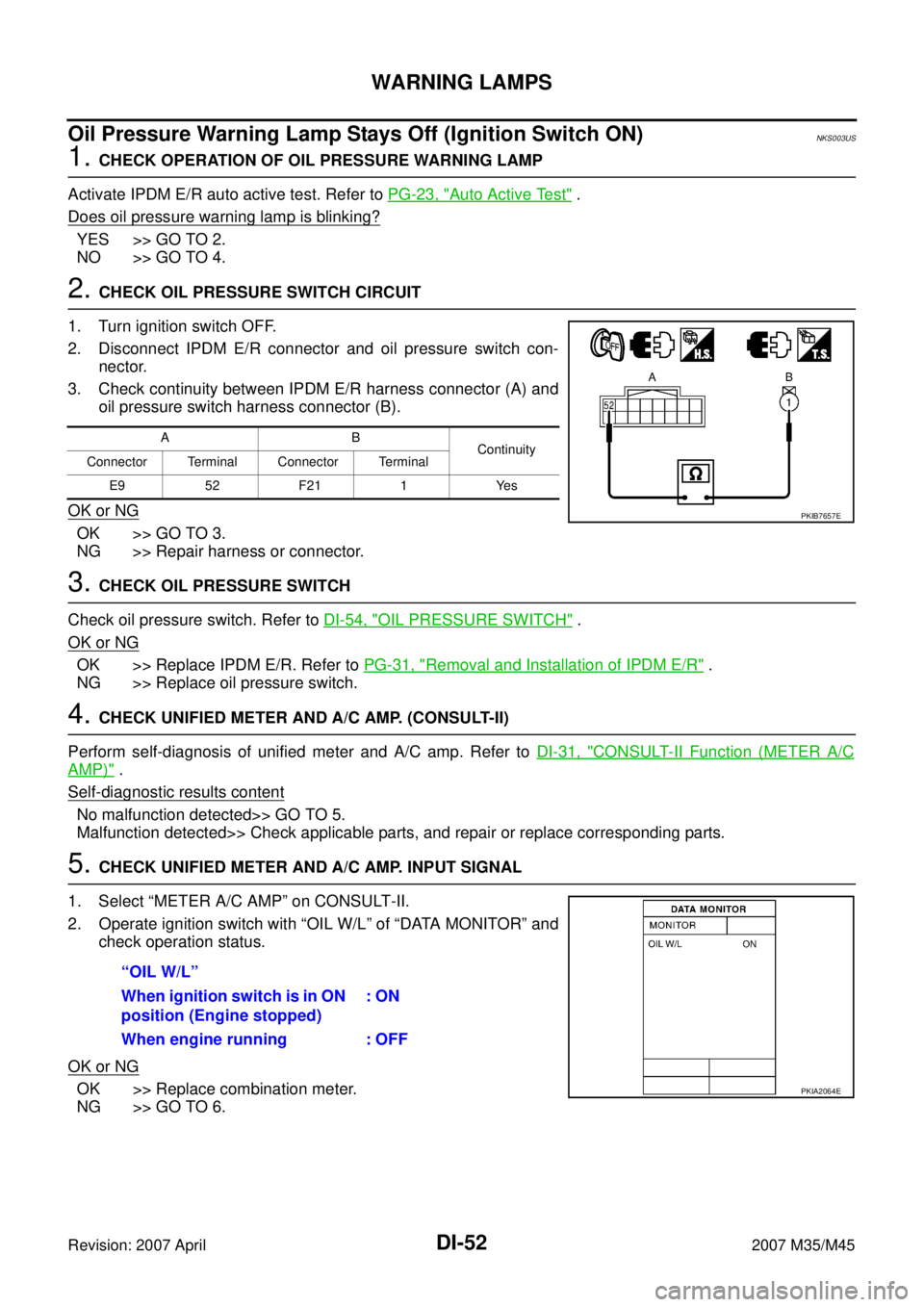
2. CHECK OIL PRESSURE SWITCH CIRCUIT
1. Turn ignition switch OFF.
2. Disconnect IPDM E/R connector and oil pressure switch con-
nector.
3. Check continuity between IPDM E/R harness connector (A) and
oil pressure switch harness connector (B).
OK or NG
OK >> GO TO 3.
NG >> Repair harness or connector.
3. CHECK OIL PRESSURE SWITCH
Check oil pressure switch. Refer to DI-54, "
OIL PRESSURE SWITCH" .
OK or NG
OK >> Replace IPDM E/R. Refer to PG-31, "Removal and Installation of IPDM E/R" .
NG >> Replace oil pressure switch.
4. CHECK UNIFIED METER AND A/C AMP. (CONSULT-II)
Perform self-diagnosis of unified meter and A/C amp. Refer to DI-31, "
CONSULT-II Function (METER A/C
AMP)" .
Self
-diagnostic results content
No malfunction detected>> GO TO 5.
Malfunction detected>> Check applicable parts, and repair or replace corresponding parts.
5. CHECK UNIFIED METER AND A/C AMP. INPUT SIGNAL
1. Select “METER A/C AMP” on CONSULT-II.
2. Operate ignition switch with “OIL W/L” of “DATA MONITOR” and
check operation status.
OK or NG
OK >> Replace combination meter.
NG >> GO TO 6.
AB
Continuity
Connector Terminal Connector Terminal
E9 52 F21 1 Yes
PKIB7657E
“OIL W/L”
When ignition switch is in ON
position (Engine stopped): ON
When engine running : OFF
PKIA2064E
Page 1473 of 4647
DI-54
WARNING LAMPS
Revision: 2007 April2007 M35/M45
4. CHECK OIL PRESSURE SWITCH CIRCUIT
1. Turn ignition switch OFF.
2. Disconnect IPDM E/R connector.
3. Check continuity between IPDM E/R harness connector and
ground.
OK or NG
OK >> Replace IPDM E/R. Refer to PG-31, "Removal and
Installation of IPDM E/R" .
NG >> Repair harness or connector.
5. CHECK IPDM E/R (CONSULT-II)
Perform self-diagnosis of IPDM E/R. Refer to PG-20, "
CONSULT-II Function (IPDM E/R)" .
Self
-diagnostic results content
No malfunction detected>> Replace combination meter.
Malfunction detected>> Check applicable parts, and repair or replace corresponding parts.
Electrical Component InspectionNKS003UU
OIL PRESSURE SWITCH
Check continuity between oil pressure switch and ground.
IPDM E/R connector Terminal
GroundContinuity
E9 52 No
PKIB7659E
Condition
Oil pressure [kPa (kg/cm2 , psi)]Continuity
Engine stopped Less than 29 (0.3, 4) Yes
Engine running More than 29 (0.3, 4) No
ELF0044D
Page 1477 of 4647

DI-58
A/T INDICATOR
Revision: 2007 April2007 M35/M45
A/T Indicator Is MalfunctionNKS003UX
1. CHECK SEGMENTS OF A/T INDICATOR
Perform self-diagnosis mode of combination meter. Refer to DI-17, "
OPERATION PROCEDURE" .
Are all segments displayed?
YES >> GO TO 2.
NO >> Replace combination meter.
2. CHECK UNIFIED METER AND A/C AMP. (CONSULT-II)
Perform self-diagnosis of unified meter and A/C amp. Refer to DI-31, "
CONSULT-II Function (METER A/C
AMP)" .
Self
-diagnostic results content
No malfunction detected>> GO TO 3.
Malfunction detected>> Check applicable parts, and repair or replace corresponding parts.
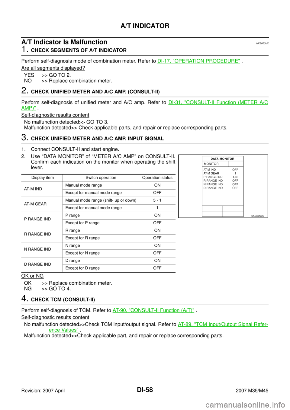
3. CHECK UNIFIED METER AND A/C AMP. INPUT SIGNAL
1. Connect CONSULT-II and start engine.
2. Use “DATA MONITOR” of “METER A/C AMP” on CONSULT-II.
Confirm each indication on the monitor when operating the shift
lever.
OK or NG
OK >> Replace combination meter.
NG >> GO TO 4.
4. CHECK TCM (CONSULT-II)
Perform self-diagnosis of TCM. Refer to AT- 9 0 , "
CONSULT-II Function (A/T)" .
Self-diagnostic results content
No malfunction detected>>Check TCM input/output signal. Refer to AT- 8 9 , "TCM Input/Output Signal Refer-
ence Values" .
Malfunction detected>>Check applicable part, and repair or replace corresponding parts.
Display item Switch operation Operation status
AT - M I N DManual mode range ON
Except for manual mode range OFF
AT - M G E A RManual mode range (shift- up or down) 5 - 1
Except for manual mode range 1
P RANGE INDP range ON
Except for P range OFF
R RANGE INDR range ON
Except for R range OFF
N RANGE INDN range ON
Except for N range OFF
D RANGE INDD range ON
Except for D range OFF
SKIA6259E
Page 1480 of 4647
WARNING CHIME
DI-61
C
D
E
F
G
H
I
J
L
MA
B
DI
Revision: 2007 April2007 M35/M45
Component Parts and Harness Connector LocationNKS003UZ
PKIB7661E
Page 1489 of 4647

DI-70
WARNING CHIME
Revision: 2007 April2007 M35/M45
Trouble DiagnosisNKS003V7
HOW TO PERFORM TROUBLE DIAGNOSIS
1. Confirm the symptom and customer complaint.
2. Understand the outline of system. Refer to DI-59, "
System Description" .
3. Perform the preliminary inspection. Refer to DI-70, "
PRELIMINARY INSPECTION" .
4. Referring to trouble diagnosis chart, make sure the cause of the malfunction and repair or replace applica-
ble parts. Refer to DI-70, "
SYMPTOM CHART" .
5. Does warning chime system operate normally? If yes, GO TO 6. If no, GO TO 3.
6. INSPECTION END
PRELIMINARY INSPECTION
1. CHECK BCM (CONSULT-II)
Perform self-diagnosis of BCM. Refer to BCS-12, "
CONSULT-II Function (BCM)" .
Self
-diagnostic results content
No malfunction detected>> GO TO 2.
Malfunction detected>> Check applicable parts, and repair or replace corresponding parts.
2. CHECK UNIFIED METER AND A/C AMP. (CONSULT-II)
Perform self-diagnosis of unified meter and A/C amp. Refer to DI-69, "
CONSULT-II Function (METER A/C
AMP)" .
Self
-diagnostic results content
No malfunction detected>> INSPECTION END
Malfunction detected>> Check applicable parts, and repair or replace corresponding parts.
SYMPTOM CHART
Meter Buzzer Circuit InspectionNKS004F7
1. CHECK BATTERY POWER SUPPLY OF COMBINATION METER
Check battery power supply of combination meter. Refer to DI-19, "
Power Supply and Ground Circuit Inspec-
tion" in combination meter.
OK or NG
OK >> GO TO 2.
NG >> Repair battery power supply circuit of combination meter.
Symptom Diagnosis/Service procedure
All warning chime systems do not activate. Perform DI-70, "
Meter Buzzer Circuit Inspection" .
Light warning chime does not activate.Perform the following inspections.
1.DI-71, "
Lighting Switch Signal Inspection"
2.DI-72, "Front Door Switch (Driver Side) Signal Inspection"
Replace BCM, found normal function in the above inspections.
Seat belt warning chime does not activate.Perform DI-73, "
Seat Belt Buckle Switch Signal Inspection" .
Replace BCM, found normal function in the above inspection.
Page 1504 of 4647
LANE DEPARTURE WARNING SYSTEM
DI-85
C
D
E
F
G
H
I
J
L
MA
B
DI
Revision: 2007 April2007 M35/M45
Component Parts and Harness Connector LocationNKS003VJ
PKIB7670E
Page 1511 of 4647

DI-92
LANE DEPARTURE WARNING SYSTEM
Revision: 2007 April2007 M35/M45
Trouble DiagnosisNKS003VN
HOW TO PERFORM TROUBLE DIAGNOSIS
1. Check the symptom and customer complaint.
2. Understand the outline of system. Refer to DI-75, "
System Description" .
3. Perform the preliminary inspection. Refer to DI-92, "
PRELIMINARY INSPECTION" .
4. Referring to symptom chart, make sure the cause of the malfunction and repair or replace applicable
parts. Refer to DI-93, "
SYMPTOM CHART" .
5. Erase DTC and perform self-diagnosis of LDW system again. Then perform LDW system running test.
Refer to DI-88, "
CONSULT-II Function (LDW)" and DI-77, "LDW SYSTEM RUNNING TEST" .
6. Does LDW system operate normally? If yes, GO TO 7. If no, GO TO 3.
7. INSPECTION END
PRELIMINARY INSPECTION
1. CHECK CAMERA LENS AND WINDSHIELD
Are camera lens and windshield contaminated with foreign materials?
YES >> Clean camera lens and windshield.
NO >> GO TO 2.
2. CHECK CAMERA UNIT INSTALLATION CONDITION
Check camera unit installation condition (installation position, properly tightened, a bent bracket).
OK or NG
OK >> GO TO 3.
NG >> Install camera unit properly, and adjust camera aiming. Refer to DI-78, "
Camera Aiming Adjust-
ment" .
3. CHECK VEHICLE HEIGHT
Check vehicle height. Refer to FSU-19, "
SERVICE DATA AND SPECIFICATIONS (SDS)" (2WD) or FSU-37,
"SERVICE DATA AND SPECIFICATIONS (SDS)" (AWD).
Is vehicle height appropriate?
OK >> GO TO 4.
NG >> Repair vehicle to appropriate height.
4. CHECK LDW CAMERA UNIT (CONSULT-II)
Perform self-diagnosis of LDW camera unit. Refer to DI-88, "
CONSULT-II Function (LDW)" .
Self
-diagnostic results content
No malfunction detected>>GO TO 5.
Malfunction detected>>Check applicable parts, and repair or replace corresponding parts.
5. CHECK COMBINATION METER
Check combination meter function.
Do speedometer and turn signal indicator function normally?
YES >> INSPECTION END
NO >> Check combination meter. Refer to DI-18, "
Trouble Diagnosis" .
Page 1513 of 4647

DI-94
LANE DEPARTURE WARNING SYSTEM
Revision: 2007 April2007 M35/M45
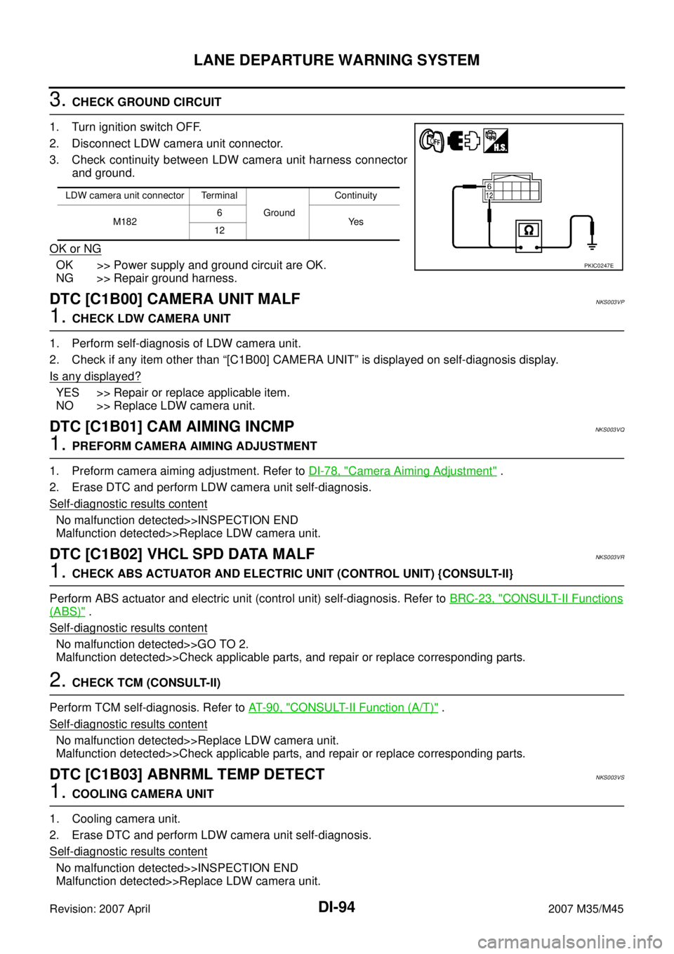
3. CHECK GROUND CIRCUIT
1. Turn ignition switch OFF.
2. Disconnect LDW camera unit connector.
3. Check continuity between LDW camera unit harness connector
and ground.
OK or NG
OK >> Power supply and ground circuit are OK.
NG >> Repair ground harness.
DTC [C1B00] CAMERA UNIT MALFNKS003VP
1. CHECK LDW CAMERA UNIT
1. Perform self-diagnosis of LDW camera unit.
2. Check if any item other than “[C1B00] CAMERA UNIT” is displayed on self-diagnosis display.
Is any displayed?
YES >> Repair or replace applicable item.
NO >> Replace LDW camera unit.
DTC [C1B01] CAM AIMING INCMPNKS003VQ
1. PREFORM CAMERA AIMING ADJUSTMENT
1. Preform camera aiming adjustment. Refer to DI-78, "
Camera Aiming Adjustment" .
2. Erase DTC and perform LDW camera unit self-diagnosis.
Self
-diagnostic results content
No malfunction detected>>INSPECTION END
Malfunction detected>>Replace LDW camera unit.
DTC [C1B02] VHCL SPD DATA MALFNKS003VR
1. CHECK ABS ACTUATOR AND ELECTRIC UNIT (CONTROL UNIT) {CONSULT-II}
Perform ABS actuator and electric unit (control unit) self-diagnosis. Refer to BRC-23, "
CONSULT-II Functions
(ABS)" .
Self
-diagnostic results content
No malfunction detected>>GO TO 2.
Malfunction detected>>Check applicable parts, and repair or replace corresponding parts.
2. CHECK TCM (CONSULT-II)
Perform TCM self-diagnosis. Refer to AT- 9 0 , "
CONSULT-II Function (A/T)" .
Self
-diagnostic results content
No malfunction detected>>Replace LDW camera unit.
Malfunction detected>>Check applicable parts, and repair or replace corresponding parts.
DTC [C1B03] ABNRML TEMP DETECTNKS003VS
1. COOLING CAMERA UNIT
1. Cooling camera unit.
2. Erase DTC and perform LDW camera unit self-diagnosis.
Self
-diagnostic results content
No malfunction detected>>INSPECTION END
Malfunction detected>>Replace LDW camera unit.
LDW camera unit connector Terminal
GroundContinuity
M1826
Ye s
12
PKIC0247E