Page 4326 of 4647

CLIMATE CONTROLLED SEAT
SE-127
C
D
E
F
G
H
J
K
L
MA
B
SE
Revision: 2007 April2007 M35/M45
Check Climate Controlled Seat Control Unit Power Supply Circuit NIS0027P
1. CHECK FUSE
Check 10A fuse [No. 12, located in fuse block (J/B)]
NOTE:
Refer to SE-114, "
Component Parts and Harness Connector Location" .
OK or NG
OK >> GO TO 2.
NG >> If fuse is blown, be sure to eliminate cause of malfunction before installing new fuse, refer to PG-
3, "POWER SUPPLY ROUTING CIRCUIT" .
2. CHECK CLIMATE CONTROLLED SEAT RELAY POWER SUPPLY CIRCUIT
1. Disconnect climate controlled seat relay connector.
2. Turn ignition switch ON.
3. Check voltage between climate controlled seat relay harness
connector and ground.
OK or NG
OK >> GO TO 3.
NG >> Repair or replace harness between fuse block (J/B) and
climate controlled seat relay.
3. CHECK CLIMATE CONTROLLED SEAT RELAY
Check continuity climate controlled seat relay.
OK or NG
OK >> GO TO 4.
NG >> Replace climate controlled seat relay.
Terminal
Voltage (V)
(Approx.) (+)
(–)
Climate controlled
seat relay connectorTerminal
E16 2 Ground Battery voltage
PIIB6067E
Climate controlled
seat relay connectorTerminal Condition Continuity
E163512V direct current
supply between
terminals 1and 2Ye s
No current supply No
6712V direct current
supply between
terminals 1and 2Ye s
No current supply No
SEC202B
Page 4327 of 4647

SE-128
CLIMATE CONTROLLED SEAT
Revision: 2007 April2007 M35/M45
4. CHECK CLIMATE CONTROLLED SEAT RELAY GROUND CIRCUIT
1. Turn ignition switch OFF.
2. Check continuity between climate controlled seat relay connec-
tor and ground.
OK or NG
OK >> Check the condition of the harness and connector.
NG >> Repair or replace harness between climate controlled
seat relay and ground.
Check Climate Controlled Seat Control Unit Power Supply and Ground Circuit NIS0027Q
1. CHECK CLIMATE CONTROLLED SEAT CONTROL UNIT POWER SUPPLY CIRCUIT
1. Disconnect climate controlled seat control unit connector.
2. Turn ignition switch ON.
3. Check voltage between climate controlled seat control unit con-
nector and ground.
OK or NG
OK >> GO TO 6.
NG >> GO TO 2.
2. CHECK FUSE
�Check 15A fuse [No. 42, located in fuse, fusible link and relay unit] (Driver side)
�Check 15A fuse [No. 41, located in fuse, fusible link and relay unit] (Passenger side)
NOTE:
Refer to SE-114, "
Component Parts and Harness Connector Location" .
OK or NG
OK >> GO TO 3.
NG >> If fuse is blown, be sure to eliminate cause of malfunction before installing new fuse, refer to PG-
3, "POWER SUPPLY ROUTING CIRCUIT" .
Te r m i n a l
Continuity
Climate controlled
seat relay connectorTerminal
Ground
E16 1 Yes
PIIB6068E
Te r m i n a l
Voltage (V)
(Approx.) (+)
(–)
Climate controlled seat
control unit connectorTerminal
B284
(driver side)
B294
(passenger side)2
Ground Battery voltage
4
PIIB6069E
Page 4343 of 4647

SE-144
HEATED SEAT
Revision: 2007 April2007 M35/M45
HEATED SEATPFP:87335
Component Parts and Harness Connector LocationNIS00280
System Description NIS00281
NOTE:
�When handling seat, be extremely careful not to scratch heating unit
�To replace heating unit, seat trim and pad should be separated.
�Do not use any organic solvent, such as thinner, benzene, alcohol, etc. to clean trims.
Power is all time supplied
�to rear LH seat control unit and rear RH seat control unit terminal 1.
�through 50A fusible link [Letter F, located in the fuse block (J/B)],
�to IPDM E/R (heated seat relay) terminal 14.
�through 15A fuse [No.38, located in the fuse block (J/B)].
With the ignition switch to ON or START position, power is supplied
�to rear LH seat control unit terminal 4 and
�to rear heated seat switch LH terminal 6.
�through IPDM E/R (heated seat relay) terminal 12
�to rear RH seat control unit terminal 4 and
�to rear heated seat switch RH terminal 6
�through IPDM E/R (heated seat relay) terminal 9.
1. Fuse, fusible link and relay block (J/B) 2. IPDM E/R E5, E6, E9 3. Heated seat relay E5, E6, E9
(Built into the IPDM E/R)
4. a: Rear heated seat switch LH B507
b: Rear heated seat switch RH B5585. Rear seat control unit
B303, B304 (LH)
B353, B354 (RH)
(View with the rear seatback
removed)
PIIB5890E
Page 4352 of 4647

HEATED SEAT
SE-153
C
D
E
F
G
H
J
K
L
MA
B
SE
Revision: 2007 April2007 M35/M45
Check Rear Heated Seat Power Supply and Ground CircuitNIS00287
1. CHECK FUSIBLE LINK AND FUSE
�Check 50A fusible link (letter F located in the fuse and fusible link box).
�Check 15A fuse (No.38, located in fuse block).
�Check circuit breaker.
NOTE:
Refer to SE-144, "
Component Parts and Harness Connector Location" .
OK or NG
OK >> GO TO 2.
NG >> If fuse or circuit breaker is blown, be sure to eliminate cause of malfunction before installing new
fuse or new circuit breaker, refer to PG-3, "
POWER SUPPLY ROUTING CIRCUIT" .
2. CHECK HEATED SEAT RELAY POWER SUPPLY CIRCUIT
1. Turn ignition switch OFF.
2. Check voltage between IPDM E/R (heated seat relay) connector
and ground.
OK or NG
OK >> GO TO 3.
NG >> Repair or replace harness between fuse block (J/B) and IPDM E/R (heated seat relay).
3. CHECK HEATED SEAT RELAY GROUND CIRCUIT
1. Disconnect IPDM E/R (heated seat relay) connector.
2. Check continuity between IPDM E/R (heated seat relay) con-
nector and ground.
OK or NG
OK >> Check the condition of the harness and connector.
NG >> Repair or replace harness between IPDM E/R (heated
seat relay) and ground.
Terminal
Voltage (V)
(Approx.) (+)
(–) IPDM E/R
(heated seat relay)
connectorTerminal
E6 14 Ground Battery voltage
PIIB5995E
Terminal
Continuity IPDM E/R
(heated seat relay)
connectorTerminal
Ground
E9 54 Yes
PIIB5996E
Page 4371 of 4647
SE-172
FRONT SEAT
Revision: 2007 April2007 M35/M45
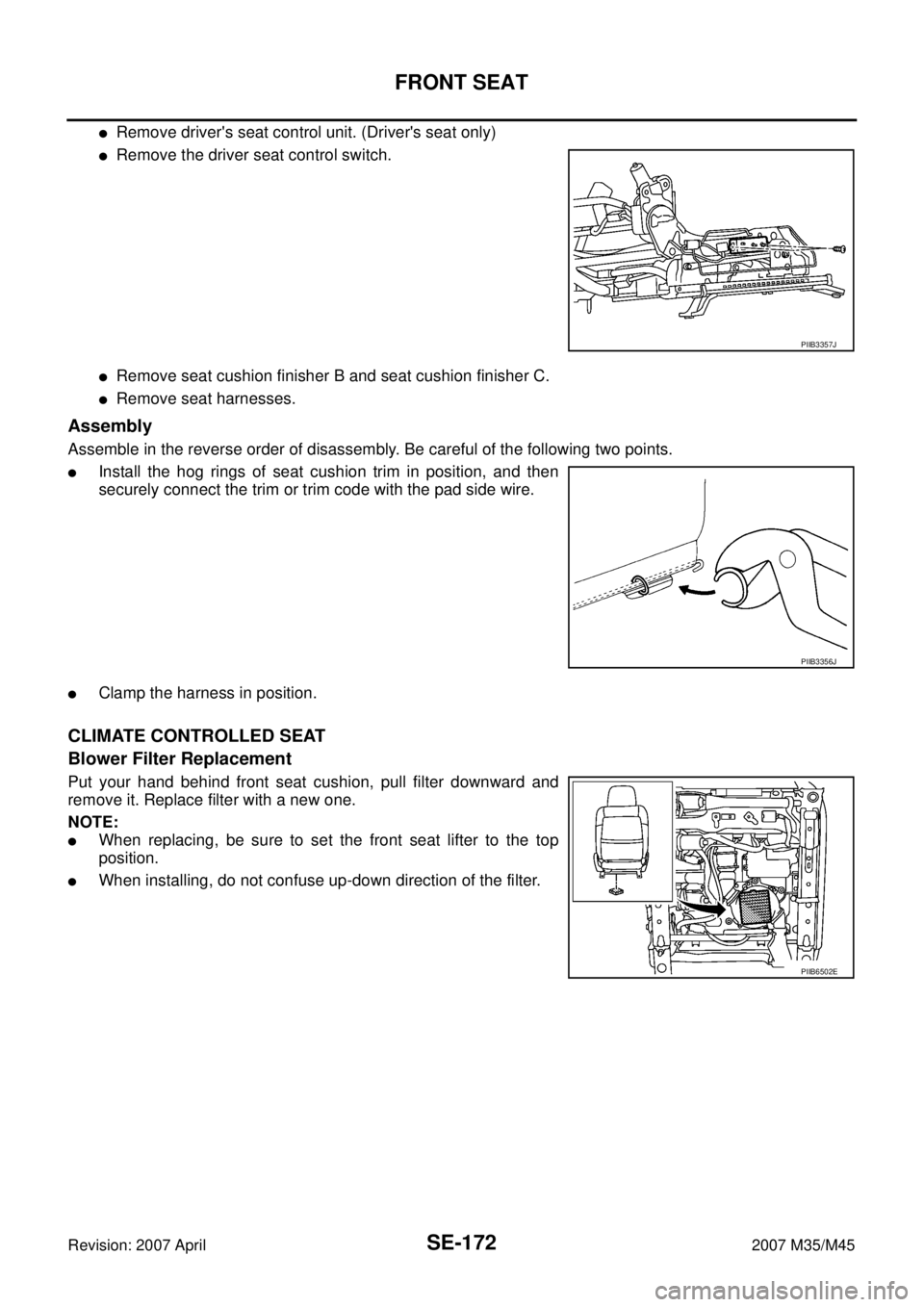
�Remove driver's seat control unit. (Driver's seat only)
�Remove the driver seat control switch.
�Remove seat cushion finisher B and seat cushion finisher C.
�Remove seat harnesses.
Assembly
Assemble in the reverse order of disassembly. Be careful of the following two points.
�Install the hog rings of seat cushion trim in position, and then
securely connect the trim or trim code with the pad side wire.
�Clamp the harness in position.
CLIMATE CONTROLLED SEAT
Blower Filter Replacement
Put your hand behind front seat cushion, pull filter downward and
remove it. Replace filter with a new one.
NOTE:
�When replacing, be sure to set the front seat lifter to the top
position.
�When installing, do not confuse up-down direction of the filter.
PIIB3357J
PIIB3356J
PIIB6502E
Page 4390 of 4647

TROUBLE DIAGNOSIS
SRS-9
C
D
E
F
G
I
J
K
L
MA
B
SRS
Revision: 2007 April2007 M35/M45
TROUBLE DIAGNOSISPFP:00004
Trouble Diagnosis IntroductionNHS00090
CAUTION:
�Do not use electrical test equipment on any circuit related to the SRS unless instructed in this Ser-
vice Manual. SRS wiring harnesses can be identified by yellow and/or orange harnesses or har-
ness connectors.
�Do not repair, splice or modify the SRS wiring harness. If the harness is damaged, replace it with a
new one.
�Keep ground portion clean.
DIAGNOSIS FUNCTION
The SRS self-diagnosis results can be read by using “AIR BAG” warning lamp and/or CONSULT-II.
The User mode is exclusively prepared for the customer (driver). This mode warns the driver of a system mal-
function through the operation of the “AIR BAG” warning lamp.
The Diagnosis mode allows the technician to locate and inspect the malfunctioning part.
The mode applications for the “AIR BAG” warning lamp and CONSULT-II are as follows:
HOW TO PERFORM TROUBLE DIAGNOSIS FOR QUICK AND ACCURATE REPAIR
A good understanding of the malfunction conditions can make troubleshooting faster and more accurate.
In general, each customer feels differently about a malfunction. It is important to fully understand the symp-
toms or conditions for a customer complaint.
Information from Customer
WHAT..... Vehicle model
WHEN..... Date, Frequencies
WHERE..... Road conditions
HOW..... Operating conditions, Symptoms
Preliminary Check
Make sure the following parts are in good order.
�Battery (Refer to SC-4, "How to Handle Battery" .)
�Fuse (Refer to SRS-13, "Wiring Diagram — SRS —" .)
�System component-to-harness connections
User mode Diagnosis mode Display type
“AIR BAG” warning lamp X X ON-OFF operation
CONSULT-II — X Monitoring
Page 4420 of 4647

TROUBLE DIAGNOSIS
SRS-39
C
D
E
F
G
I
J
K
L
MA
B
SRS
Revision: 2007 April2007 M35/M45
Trouble Diagnosis: “AIR BAG” Warning Lamp Does Not Turn OFFNHS00099
DIAGNOSTIC PROCEDURE 7
1. CHECK THE DEPLOYMENT OF AIR BAG MODULE
Is air bag module deployed?
YES or NO
YES >> Refer to SRS-54, "COLLISION DIAGNOSIS" .
NO >> GO TO 2.
2. CHECK THE AIR BAG FUSE
Check 10A fuse [No.13, located in fuse block (J/B)].
Refer to PG-3, "
POWER SUPPLY ROUTING CIRCUIT" .
OK or NG
OK >> GO TO 4.
NG >> GO TO 3.
3. CHECK AIR BAG FUSE AGAIN
Replace “AIR BAG” fuse and turn ignition switch ON.
Does the
“AIR BAG” fuse blow again?
YES >> Repair or replace main harness.
NO >>INSPECTION END
4. CHECK DIAGNOSIS SENSOR UNIT
Connect CONSULT-II and touch “START”.
Is “AIR BAG” displayed on CONSULT-II?
YES or NO
YES >> GO TO 5.
NO >> Visually check the wiring harness connection of diagno-
sis sensor unit. If the harness connection check result is
OK, replace diagnosis sensor unit.
5. CHECK HARNESS CONNECTION
Is harness connection between warning lamp and diagnosis sensor unit OK?
OK or NG
OK >> Replace diagnosis sensor unit.
NG >> Connect “AIR BAG” warning lamp and diagnosis sensor unit connector properly. If “AIR BAG”
warning lamp still does not go off, replace harness.
BCIA0030E
Page 4421 of 4647
SRS-40
TROUBLE DIAGNOSIS
Revision: 2007 April2007 M35/M45
Trouble Diagnosis: “AIR BAG” Warning Lamp Does Not Turn ONNHS0009A
DIAGNOSTIC PROCEDURE 8
1. CHECK METER FUSE
Check 10A fuse [No.14, located in fuse block (J/B)].
Refer to PG-3, "
POWER SUPPLY ROUTING CIRCUIT" .
OK or NG
OK >> GO TO 3.
NG >> GO TO 2.
2. CHECK METER FUSE AGAIN
Replace 10A fuse [No.14, located in fuse block (J/B)] and turn ignition switch ON.
Does the meter fuse blow again?
YES >> Repair or replace the related harness.
NO >>INSPECTION END
3. CHECK HARNESS CONNECTION BETWEEN DIAGNOSIS SENSOR UNIT AND COMBINATION
METER
Disconnect diagnosis sensor unit connector and turn ignition switch ON.
Does “AIR BAG” warning lamp turn ON?
YES or NO
YES >> Replace diagnosis sensor unit.
NO >> Replace combination meter assembly.