Page 2918 of 4647
![INFINITI M35 2007 Factory Service Manual FUEL INJECTOR
EC-1389
[VK45DE]
C
D
E
F
G
H
I
J
K
L
MA
EC
Revision: 2007 April2007 M35/M45
FUEL INJECTORPFP:16600
Component DescriptionNBS005PV
The fuel injector is a small, precise solenoid valve. Whe INFINITI M35 2007 Factory Service Manual FUEL INJECTOR
EC-1389
[VK45DE]
C
D
E
F
G
H
I
J
K
L
MA
EC
Revision: 2007 April2007 M35/M45
FUEL INJECTORPFP:16600
Component DescriptionNBS005PV
The fuel injector is a small, precise solenoid valve. Whe](/manual-img/42/57024/w960_57024-2917.png)
FUEL INJECTOR
EC-1389
[VK45DE]
C
D
E
F
G
H
I
J
K
L
MA
EC
Revision: 2007 April2007 M35/M45
FUEL INJECTORPFP:16600
Component DescriptionNBS005PV
The fuel injector is a small, precise solenoid valve. When the ECM
supplies a ground to the fuel injector circuit, the coil in the fuel injec-
tor is energized. The energized coil pulls the ball valve back and
allows fuel to flow through the fuel injector into the intake manifold.
The amount of fuel injected depends upon the injection pulse dura-
tion. Pulse duration is the length of time the fuel injector remains
open. The ECM controls the injection pulse duration based on
engine fuel needs.
CONSULT-II Reference Value in Data Monitor ModeNBS005PW
Specification data are reference values.
SEF375Z
MONITOR ITEM CONDITION SPECIFICATION
B/FUEL SCHDL See EC-847, "
TROUBLE DIAGNOSIS - SPECIFICATION VALUE" .
INJ PULSE-B1
INJ PULSE-B2
�Engine: After warming up
�Selector lever: P or N
�Air conditioner switch: OFF
�No loadIdle 2.0 - 3.0 msec
2,000 rpm 1.9 - 2.9 msec
Page 2958 of 4647
![INFINITI M35 2007 Factory Service Manual VIAS
EC-1429
[VK45DE]
C
D
E
F
G
H
I
J
K
L
MA
EC
Revision: 2007 April2007 M35/M45
VIASPFP:14956
DescriptionNBS005PK
SYSTEM DESCRIPTION
*: The ECM determines the start signal status by the signals of en INFINITI M35 2007 Factory Service Manual VIAS
EC-1429
[VK45DE]
C
D
E
F
G
H
I
J
K
L
MA
EC
Revision: 2007 April2007 M35/M45
VIASPFP:14956
DescriptionNBS005PK
SYSTEM DESCRIPTION
*: The ECM determines the start signal status by the signals of en](/manual-img/42/57024/w960_57024-2957.png)
VIAS
EC-1429
[VK45DE]
C
D
E
F
G
H
I
J
K
L
MA
EC
Revision: 2007 April2007 M35/M45
VIASPFP:14956
DescriptionNBS005PK
SYSTEM DESCRIPTION
*: The ECM determines the start signal status by the signals of engine speed and battery voltage.
When the engine is running at low or medium speed, the power valve is fully closed. Under this condition, the
effective suction port length is equivalent to the total length of the intake manifold collector's suction port
including the intake valve. This long suction port provides increased air intake which results in improved suc-
tion efficiency and higher torque generation.
The surge tank and one-way valve are provided. When engine is running at high speed, the ECM sends the
signal to the VIAS control solenoid valve. This signal introduces the intake manifold vacuum into the power
valve actuator and therefore opens the power valve to two suction passages together in the collector.
Under this condition, the effective port length is equivalent to the length of the suction port provided indepen-
dently for each cylinder. This shortened port length results in enhanced engine output with reduced suction
resistance under high speeds.
The power valve is always open regardless of the engine speed when gear position is in N or P.
Sensor Input signal to ECM ECM function Actuator
Crankshaft position sensor (POS)
Camshaft position sensor (PHASE)Engine speed*
VIAS control VIAS control solenoid valve Mass air flow sensor Amount of intake air
Throttle position sensor Throttle position
Accelerator pedal position sensor Accelerator pedal position
Battery Battery voltage*
Engine coolant temperature sensor Engine coolant temperature
PBIB1876E
Page 3046 of 4647

FRONT DRIVE SHAFT
FAX-9
C
E
F
G
H
I
J
K
L
MA
B
FA X
Revision: 2007 April2007 M35/M45
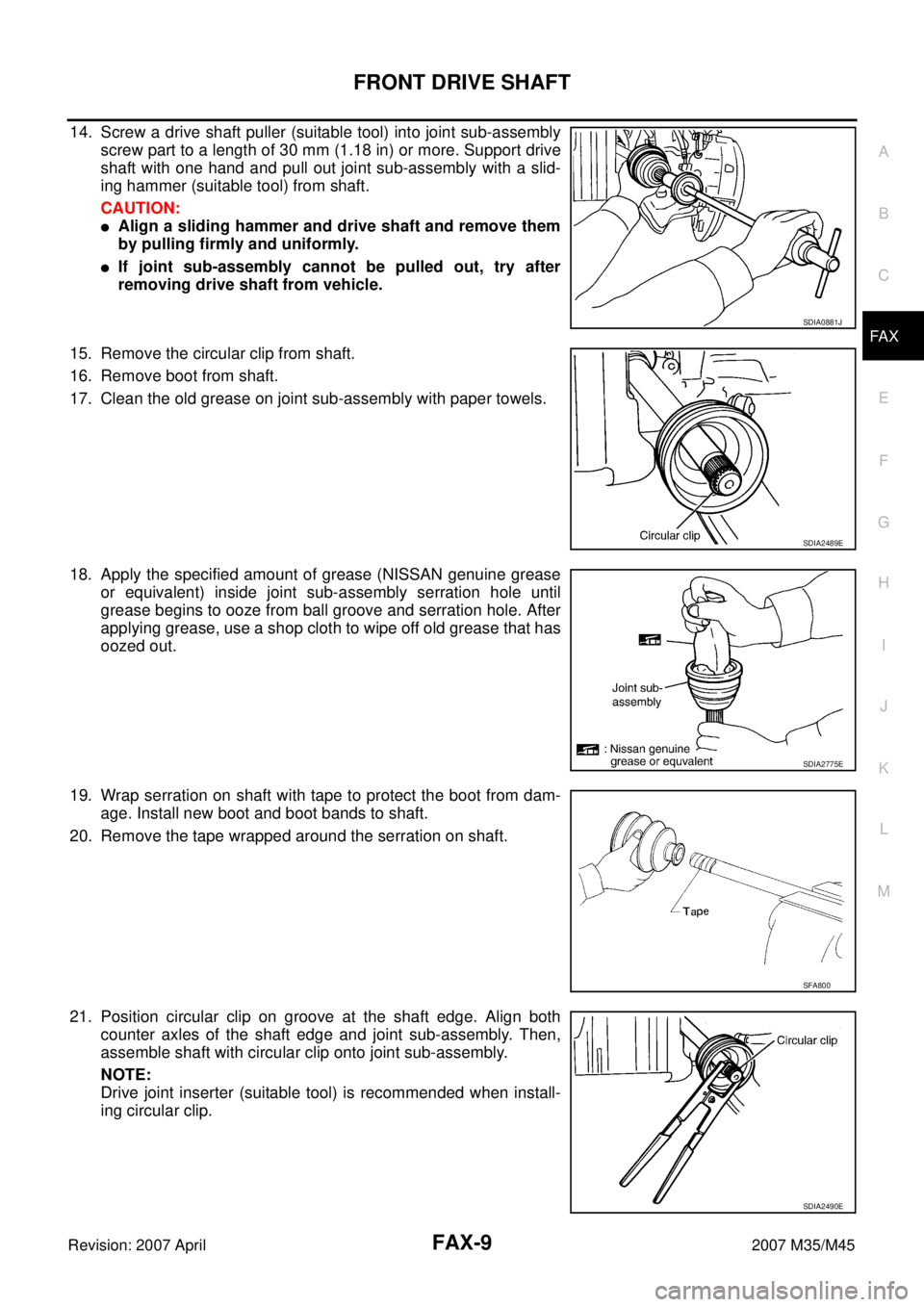
14. Screw a drive shaft puller (suitable tool) into joint sub-assembly
screw part to a length of 30 mm (1.18 in) or more. Support drive
shaft with one hand and pull out joint sub-assembly with a slid-
ing hammer (suitable tool) from shaft.
CAUTION:
�Align a sliding hammer and drive shaft and remove them
by pulling firmly and uniformly.
�If joint sub-assembly cannot be pulled out, try after
removing drive shaft from vehicle.
15. Remove the circular clip from shaft.
16. Remove boot from shaft.
17. Clean the old grease on joint sub-assembly with paper towels.
18. Apply the specified amount of grease (NISSAN genuine grease
or equivalent) inside joint sub-assembly serration hole until
grease begins to ooze from ball groove and serration hole. After
applying grease, use a shop cloth to wipe off old grease that has
oozed out.
19. Wrap serration on shaft with tape to protect the boot from dam-
age. Install new boot and boot bands to shaft.
20. Remove the tape wrapped around the serration on shaft.
21. Position circular clip on groove at the shaft edge. Align both
counter axles of the shaft edge and joint sub-assembly. Then,
assemble shaft with circular clip onto joint sub-assembly.
NOTE:
Drive joint inserter (suitable tool) is recommended when install-
ing circular clip.
SDIA0881J
SDIA2489E
SDIA2775E
SFA800
SDIA2490E
Page 3047 of 4647

FAX-10
FRONT DRIVE SHAFT
Revision: 2007 April2007 M35/M45
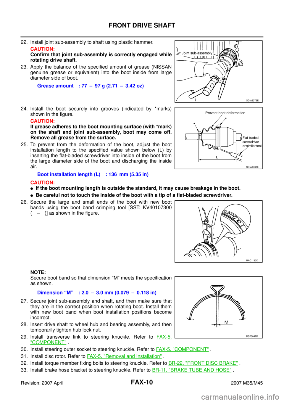
22. Install joint sub-assembly to shaft using plastic hammer.
CAUTION:
Confirm that joint sub-assembly is correctly engaged while
rotating drive shaft.
23. Apply the balance of the specified amount of grease (NISSAN
genuine grease or equivalent) into the boot inside from large
diameter side of boot.
24. Install the boot securely into grooves (indicated by *marks)
shown in the figure.
CAUTION:
If grease adheres to the boot mounting surface (with *mark)
on the shaft and joint sub-assembly, boot may come off.
Remove all grease from the surface.
25. To prevent from the deformation of the boot, adjust the boot
installation length to the specified value shown below (L) by
inserting the flat-bladed screwdriver into inside of the boot from
the large diameter side of the boot and discharging the inside
air.
CAUTION:
�If the boot mounting length is outside the standard, it may cause breakage in the boot.
�Be careful not to touch the inside of the boot with a tip of a flat-bladed screwdriver.
26. Secure the large and small ends of the boot with new boot
bands using the boot band crimping tool [SST: KV40107300
( – )] as shown in the figure.
NOTE:
Secure boot band so that dimension “M” meets the specification
as shown.
27. Secure joint sub-assembly and shaft, and then make sure that
they are in the correct position when rotating boot. Install them
with new boot band when boot installation positions become
incorrect.
28. Insert drive shaft to wheel hub and bearing assembly, and then
temporarily tighten hub lock nut.
29. Install transverse link to steering knuckle. Refer to FAX-5,
"COMPONENT" .
30. Install steering outer socket to steering knuckle. Refer to FA X - 5 , "
COMPONENT" .
31. Install disc rotor. Refer to FAX-5, "
Removal and Installation" .
32. Install torque member fixing bolts to steering knuckle. Refer to BR-22, "
FRONT DISC BRAKE" .
33. Install brake hose bracket to steering knuckle. Refer to BR-11, "
BRAKE TUBE AND HOSE" . Grease amount : 77 – 97 g (2.71 – 3.42 oz)
SDIA2372E
Boot installation length (L) : 136 mm (5.35 in)
SDIA1760E
RAC1133D
Dimension “M” : 2.0 – 3.0 mm (0.079 – 0.118 in)
DSF0047D
Page 3052 of 4647
![INFINITI M35 2007 Factory Service Manual FRONT DRIVE SHAFT
FAX-15
C
E
F
G
H
I
J
K
L
MA
B
FA X
Revision: 2007 April2007 M35/M45
ASSEMBLY
Front Final Drive Side
1. If plug has been removed, use a drift [SST] to press in a new
one. (LH side)
2. INFINITI M35 2007 Factory Service Manual FRONT DRIVE SHAFT
FAX-15
C
E
F
G
H
I
J
K
L
MA
B
FA X
Revision: 2007 April2007 M35/M45
ASSEMBLY
Front Final Drive Side
1. If plug has been removed, use a drift [SST] to press in a new
one. (LH side)
2.](/manual-img/42/57024/w960_57024-3051.png)
FRONT DRIVE SHAFT
FAX-15
C
E
F
G
H
I
J
K
L
MA
B
FA X
Revision: 2007 April2007 M35/M45
ASSEMBLY
Front Final Drive Side
1. If plug has been removed, use a drift [SST] to press in a new
one. (LH side)
2. Wrap serration on shaft with tape to protect boot from damage.
Install new boot and boot bands to shaft.
3. Remove the tape wrapped around the serration on shaft.
4. Align matching marks painted when spider assembly was
removed. Install spider assembly with chamfer facing shaft.
5. Secure spider assembly onto shaft with snap ring.
6. Apply the appropriate amount of grease (NISSAN genuine
grease or equivalent) to spider assembly and sliding surface.
7. Assemble the housing onto spider assembly, and apply the bal-
ance of the specified amount grease (NISSAN genuine grease
or equivalent).
8. Install boot securely into grooves (indicated by *marks) shown in the figure.
CAUTION:
If grease adheres to the boot mounting surface (with *mark) on shaft and housing, boot may come
off. Remove all grease from the surface.
9. To prevent from deformation of the boot, adjust the boot installation length to the value shown below (L) by
inserting a flat-bladed screwdriver or similar tool into the inside of boot from the large diameter side of
boot and discharging inside air.
SDIA1153E
SFA800
SDIA2629E
Grease amount RH side : 113 – 123 g
(3.99–4.34 oz)
LH side : 95 – 105 g
(3.35 – 3.70 oz)
SFA023A
Page 3053 of 4647

FAX-16
FRONT DRIVE SHAFT
Revision: 2007 April2007 M35/M45
CAUTION:
�If the boot installation length is outside the standard, it may cause breakage in boot.
�Be careful not to touch the inside of the boot with the tip of a flat-bladed screwdriver.
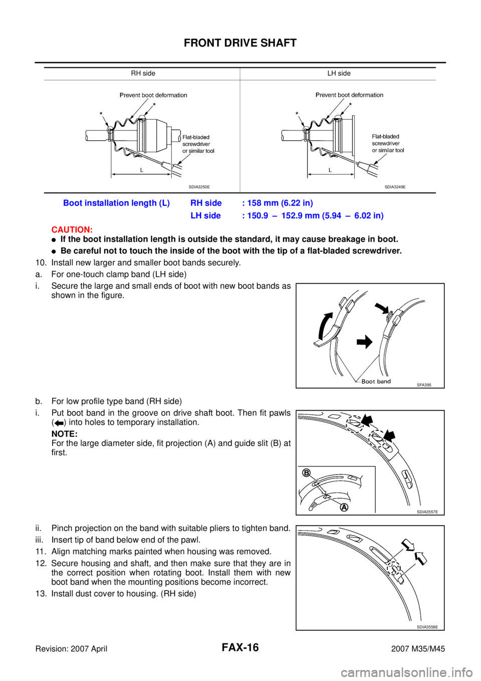
10. Install new larger and smaller boot bands securely.
a. For one-touch clamp band (LH side)
i. Secure the large and small ends of boot with new boot bands as
shown in the figure.
b. For low profile type band (RH side)
i. Put boot band in the groove on drive shaft boot. Then fit pawls
( ) into holes to temporary installation.
NOTE:
For the large diameter side, fit projection (A) and guide slit (B) at
first.
ii. Pinch projection on the band with suitable pliers to tighten band.
iii. Insert tip of band below end of the pawl.
11. Align matching marks painted when housing was removed.
12. Secure housing and shaft, and then make sure that they are in
the correct position when rotating boot. Install them with new
boot band when the mounting positions become incorrect.
13. Install dust cover to housing. (RH side)
RH side LH side
Boot installation length (L) RH side : 158 mm (6.22 in)
LH side : 150.9 – 152.9 mm (5.94 – 6.02 in)
SDIA3250ESDIA3249E
SFA395
SDIA3557E
SDIA3558E
Page 3055 of 4647
FAX-18
SERVICE DATA AND SPECIFICATIONS (SDS)
Revision: 2007 April2007 M35/M45
SERVICE DATA AND SPECIFICATIONS (SDS)PFP:00030
Wheel BearingNDS000FK
Drive ShaftNDS000FL
Axial end play0.05 mm (0.002 in) or less
Joint type Wheel side Front final drive side
Grease quantity 77 – 97 g (2.71 – 3.42 oz)113 – 123 g (3.99 – 4.34 oz) (RH side)
95 – 105 g (3.35 – 3.70 oz) (LH side)
Boots installed length 136 mm (5.35 in)158 mm (6.22 in) (RH side)
150.9 – 152.9 mm (5.94 – 6.02 in) (LH side)
Page 3102 of 4647

FUEL TANK
FL-11
C
D
E
F
G
H
I
J
K
L
MA
FL
Revision: 2007 April2007 M35/M45
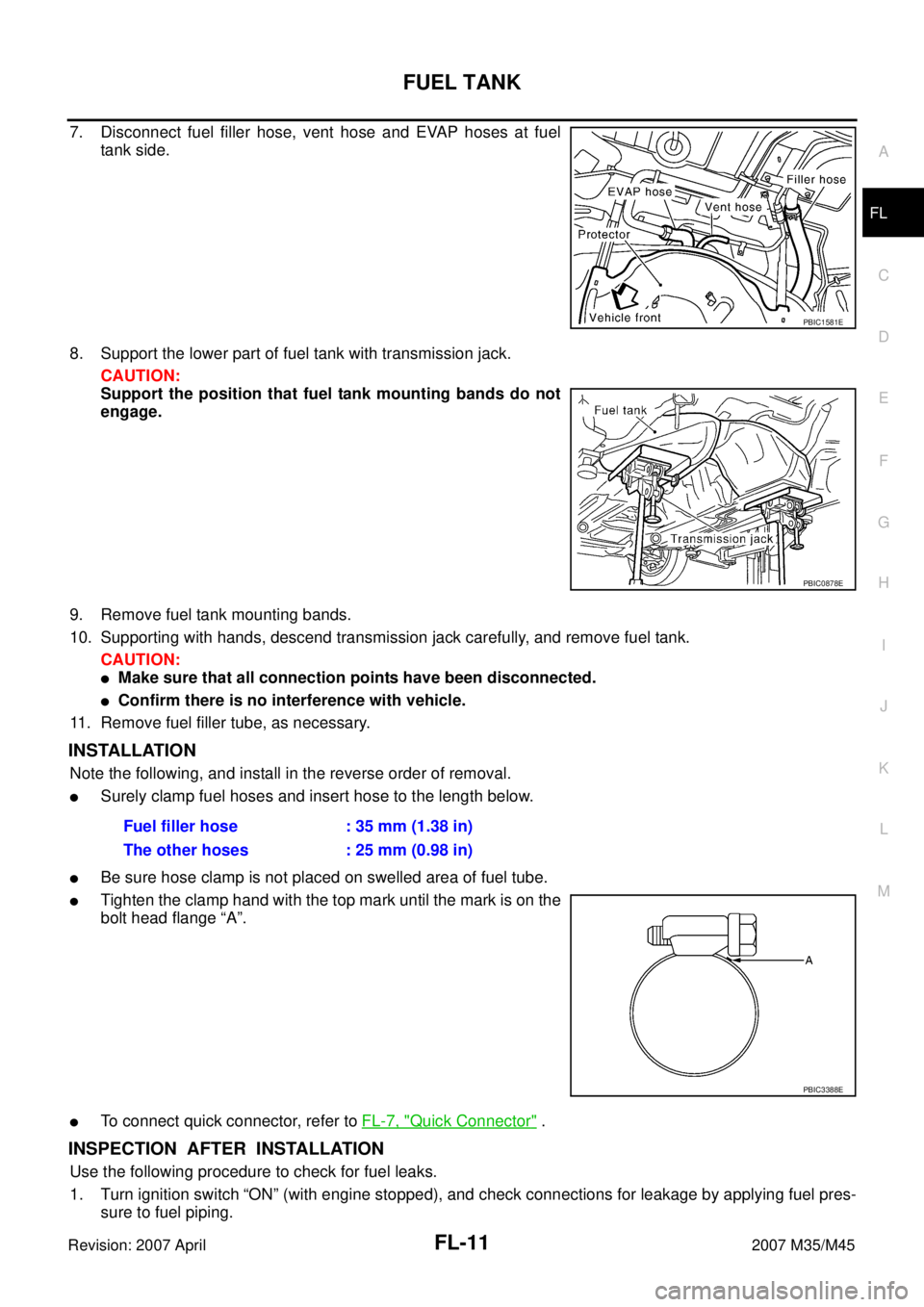
7. Disconnect fuel filler hose, vent hose and EVAP hoses at fuel
tank side.
8. Support the lower part of fuel tank with transmission jack.
CAUTION:
Support the position that fuel tank mounting bands do not
engage.
9. Remove fuel tank mounting bands.
10. Supporting with hands, descend transmission jack carefully, and remove fuel tank.
CAUTION:
�Make sure that all connection points have been disconnected.
�Confirm there is no interference with vehicle.
11. Remove fuel filler tube, as necessary.
INSTALLATION
Note the following, and install in the reverse order of removal.
�Surely clamp fuel hoses and insert hose to the length below.
�Be sure hose clamp is not placed on swelled area of fuel tube.
�Tighten the clamp hand with the top mark until the mark is on the
bolt head flange “A”.
�To connect quick connector, refer to FL-7, "Quick Connector" .
INSPECTION AFTER INSTALLATION
Use the following procedure to check for fuel leaks.
1. Turn ignition switch “ON” (with engine stopped), and check connections for leakage by applying fuel pres-
sure to fuel piping.
PBIC1581E
PBIC0878E
Fuel filler hose : 35 mm (1.38 in)
The other hoses : 25 mm (0.98 in)
PBIC3388E