Page 3150 of 4647

PRECAUTIONS
GI-7
C
D
E
F
G
H
I
J
K
L
MB
GI
Revision: 2007 April2007 M35/M45
Precautions for HosesNAS0009K
HOSE REMOVAL AND INSTALLATION
�To prevent damage to rubber hose, do not pry off rubber hose
with tapered tool or screwdriver.
�To reinstall the rubber hose securely, make sure that hose inser-
tion length and orientation is correct. (If tube is equipped with
hose stopper, insert rubber hose into tube until it butts up
against hose stopper.)
HOSE CLAMPING
�If old rubber hose is re-used, install hose clamp in its original
position (at the indentation where the old clamp was). If there is
a trace of tube bulging left on the old rubber hose, align rubber
hose at that position.
�Discard old clamps; replace with new ones.
�After installing plate clamps, apply force to them in the direction
of the arrow, tightening rubber hose equally all around.
Precautions for Engine OilsNAS0009L
Prolonged and repeated contact with used engine oil may cause skin cancer. Try to avoid direct skin contact
with used oil.
If skin contact is made, wash thoroughly with soap or hand cleaner as soon as possible.
HEALTH PROTECTION PRECAUTIONS
�Avoid prolonged and repeated contact with oils, particularly used engine oils.
SMA019D
SMA020D
SMA021D
SMA022D
Page 3194 of 4647
IDENTIFICATION INFORMATION
GI-51
C
D
E
F
G
H
I
J
K
L
MB
GI
Revision: 2007 April2007 M35/M45
Dimensions NAS00086
Unit: mm (in)
*1: 2-wheel drive model
*2: All-wheel drive model
Wheels & Tires NAS00087
*: 2-wheel drive modelOverall lengthwithout front license plate 4,893 (192.6)
with front license plate 4,899 (192.9)
Overall width 1,798 (70.8)
Overall height 1,508 (59.4)*1, 1,523 (60.0)*2
Front tread 1,537 (60.5)*1, 1,551 (61.1)*2
Rear tread 1,550 (61.0)*1, 1,543 (60.7)*2
Wheelbase 2,900 (114.2)
Conventional Spare
Road wheel/offset mm (in)18 X 8JJ Aluminum/47 (1.85)
19 X 8.5JJ Aluminum/50 (1.97)*17x4T/30 (1.18)
Tire sizeP245/45R18 96V
245/40R19 94W*T145/80D17 107M
Page 3980 of 4647

PR-13
C
E
F
G
H
I
J
K
L
MA
B
PR
Revision: 2007 April2007 M35/M45
SERVICE DATA AND SPECIFICATIONS (SDS)PFP:00030
General SpecificationsNDS000EH
2WD MODELS
*1: Spid")
SERVICE DATA AND SPECIFICATIONS (SDS)
PR-13
C
E
F
G
H
I
J
K
L
MA
B
PR
Revision: 2007 April2007 M35/M45
SERVICE DATA AND SPECIFICATIONS (SDS)PFP:00030
General SpecificationsNDS000EH
2WD MODELS
*1: Spider to spider
*2: Spider to rebro joint center
*3: Rubber coupling center to rebro joint center
*4: Rebro joint center to rebro joint center
AWD MODELS
Applied model VQ35DE VK45DE
Propeller shaft model 3S80A-1VL107 3F-R-2VL107
Number of joints3
Type of journal bearings
(Non-disassembly type)1st joint Shell type Rubber coupling type
2nd joint Shell type Rebro joint type
3rd joint Rebro joint type Rebro joint type
Coupling method with transmission Sleeve type Flange type
Coupling method with rear final drive Flange type
Shaft length1st
724 mm (28.50 in)
*1739 mm (29.09 in)*3
2nd
803 mm (31.61 in)*2802 mm (31.57 in)*4
Shaft outer diameter1st 82.6 mm (3.25 in)
2nd 82.6 mm (3.25 in)
Applied modelVQ35DE
Front Propeller shaft model 2S56A
Number of joints2
Type of journal bearings
(Non-disassembly type)Shell type
Coupling method with transfer Sleeve type
Coupling method with front final drive Flange type
Shaft length (Spider to spider) 763 mm (30.04 in)
Shaft outer diameter 42.7 mm (1.68 in)
Rear Propeller shaft model 3F80A-1VL107
Number of joints3
Type of journal bearings
(Non-disassembly type)1st joint Shell type
2nd joint Shell type
3rd joint Rebro joint type
Coupling method with transfer Flange type
Coupling method with rear final drive Flange type
Shaft length1st (Spider to spider) 399 mm (15.71 in)
2nd (Spider to rebro joint center) 803 mm (31.61 in)
Shaft outer diameter1st 82.6 mm (3.25 in)
2nd 82.6 mm (3.25 in)
Page 3983 of 4647
 ... 35
COMPONENTS .............................")
PS-2Revision: 2007 April2007 M35/M45 ASSEMBLY ......................................................... 33
Disassembly and Assembly (Models with VQ35DE) ... 35
COMPONENTS ................................................... 35
INSPECTION BEFORE DISASSEMBLY ............. 35
DISASSEMBLY ................................................... 36
INSPECTION AFTER DISASSEMBLY ................ 36
ASSEMBLY ......................................................... 37
HYDRAULIC LINE .................................................... 39
Removal and Installation ........................................ 39
COMPONENTS (VQ35DE 2WD MODELS) ........ 39
COMPONENTS (VQ35DE AWD MODELS) ........ 41
COMPONENTS (VK45DE MODELS) ................. 43
Removal and Installation ........................................ 44
SERVICE DATA AND SPECIFICATIONS (SDS) ...... 45Steering Wheel ........................................................ 45
Steering Angle ......................................................... 45
Steering Column ..................................................... 45
STEERING COLUMN LENGTH ........................... 45
TILT AND TELESCOPIC MECHANISM OPER-
ATING RANGE .................................................... 45
Steering Gear .......................................................... 46
STEERING OUTER SOCKET AND INNER
SOCKET .............................................................. 46
RACK STROKE ................................................... 46
RACK SLIDING FORCE ...................................... 46
Oil Pump ................................................................. 46
Steering Fluid .......................................................... 46
Page 3997 of 4647

PS-16
STEERING COLUMN
Revision: 2007 April2007 M35/M45
INSPECTION AFTER REMOVAL
�Check each part of steering column assembly for damage or other malfunctions. Replace if there are.
�Measure the length L as shown in the figure if vehicle has been
involved in a minor collision. Replace steering column assembly
if outside the standard.
�Measure steering column assembly rotating torque using preload gauge [SST: ST3127S000]. Replace
steering column assembly if outside the standard.
INSTALLATION OF STEERING COLUMN ASSEMBLY
�Installation is the reverse order of removal. For tightening torque, refer to PS-13, "COMPONENTS" .
�When installing upper joint, the angle which upper joint yoke (1)
forms with shaft center groove (A) should be at 90°.
�Adjust neutral position of steering angle sensor. Refer to BRC-6,
"Adjustment of Steering Angle Sensor Neutral Position" .
INSPECTION AFTER INSTALLATION
Make sure that steering wheel operates smoothly by turning several times from full left stop to full right stop.
SGIA1177E
Steering column length LTelescopic maximum 551 – 555 mm (21.69 – 21.85 in)
Telescopic minimum 591 – 595 mm (23.27 – 23.43 in)
Rotating torque : 0 – 0.2 N·m (0 – 0.02 kg-m, 0 – 1 in-lb)
SGIA1290E
Page 4009 of 4647

PS-28
POWER STEERING GEAR AND LINKAGE
Revision: 2007 April2007 M35/M45
19. Install large end of boot to gear housing assembly.
20. Install small end of boot to inner socket boot mounting groove.
21. Install boot clamp to boot small end.
22. Install large side of boot clamp.
�Tighten large side of boot with boot clamp (stainless wire).
�Wrap clamp around boot groove for two turns. Insert a flat-
bladed screwdriver in loops on both ends of wire. Twist 4 to
4.5 turns while pulling them with force of approximately 98 N
(10 kg, 22 lb).
�Twist boot clamp as shown. Pay attention to relationship
between winding and twisting directions.
�Twisted point of clamp is in the opposite side of adjusting
screw (1) as shown in the figure (to prevent contact with other
parts).
Measuring pointRack axial direction 5 mm (0.20 in) from housing end surface
Rack radial direction Axial direction of the adjusting screw
Vertical movement of rack 0.265 mm (0.0104 in)
SGIA1325E
Wire length L : 370 mm (14.57 in)
SGIA0163E
SGIA0164E
SGIA1186E
Page 4010 of 4647
POWER STEERING GEAR AND LINKAGE
PS-29
C
D
E
F
H
I
J
K
L
MA
B
PS
Revision: 2007 April2007 M35/M45
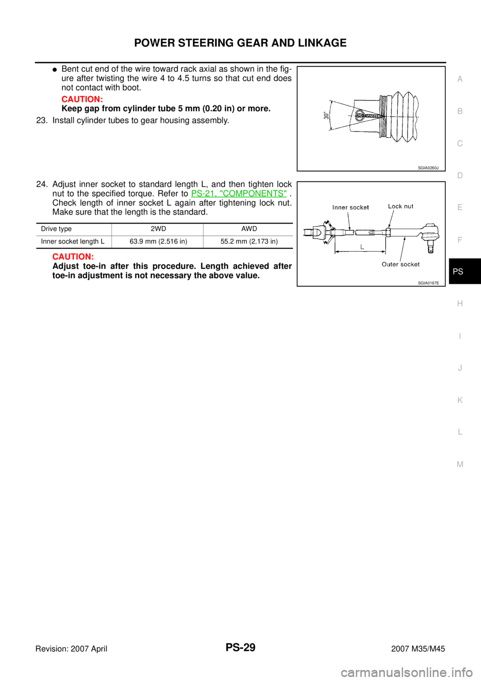
�Bent cut end of the wire toward rack axial as shown in the fig-
ure after twisting the wire 4 to 4.5 turns so that cut end does
not contact with boot.
CAUTION:
Keep gap from cylinder tube 5 mm (0.20 in) or more.
23. Install cylinder tubes to gear housing assembly.
24. Adjust inner socket to standard length L, and then tighten lock
nut to the specified torque. Refer to PS-21, "
COMPONENTS" .
Check length of inner socket L again after tightening lock nut.
Make sure that the length is the standard.
CAUTION:
Adjust toe-in after this procedure. Length achieved after
toe-in adjustment is not necessary the above value.
SGIA0260J
Drive type 2WD AWD
Inner socket length L 63.9 mm (2.516 in) 55.2 mm (2.173 in)
SGIA0167E
Page 4026 of 4647

PS-45
C
D
E
F
H
I
J
K
L
MA
B
PS
Revision: 2007 April2007 M35/M45
SERVICE DATA AND SPECIFICATIONS (SDS)PFP:00030
Steering WheelNGS000DM
Steering AngleNGS000DN
Stee")
SERVICE DATA AND SPECIFICATIONS (SDS)
PS-45
C
D
E
F
H
I
J
K
L
MA
B
PS
Revision: 2007 April2007 M35/M45
SERVICE DATA AND SPECIFICATIONS (SDS)PFP:00030
Steering WheelNGS000DM
Steering AngleNGS000DN
Steering ColumnNGS000DO
STEERING COLUMN LENGTH
TILT AND TELESCOPIC MECHANISM OPERATING RANGE
Steering wheel axial end play 0 mm (0 in)
Steering wheel play 0 – 35 mm (0 – 1.38 in)
Steering wheel turning force 7.45 N·m (0.76 kg-m, 66 in-lb)
Drive type2WD AWD
Tire size 245/45R18 245/40R19 245/45R18
Inner wheel
Degree minute (Decimal degree)Minimum 36°20′ (36.3°)39°45′ (39.8°)
Nominal 39°20′ (39.3°)42°45′ (42.8°)
Maximum 40°20′ (40.3°)43°45′ (43.8°)
Outer wheel
Degree minute (Decimal degree)Nominal 33°25′ (33.4°)33°20′ (33.3°)32°30′ (32.5°)
Steering column length LTelescopic maximum 551 – 555 mm (21.69 – 21.85 in)
Telescopic minimum 591 – 595 mm (23.27 – 23.43 in)
SGIA1177E
Tilt mechanism operating range L137.5 mm (1.476 in)
Telescopic mechanism operating range L
240 mm (1.57 in)
SGIA1179E

*1: 2-wheel drive model
*2: All-wheel drive model
Wheels & Tires NAS00087")