Page 2228 of 4647
![INFINITI M35 2007 Factory Service Manual IGNITION SIGNAL
EC-699
[VQ35DE]
C
D
E
F
G
H
I
J
K
L
MA
EC
Revision: 2007 April2007 M35/M45
5. CHECK IGNITION COIL POWER SUPPLY CIRCUIT-II
1. Turn ignition switch OFF.
2. Disconnect condenser harness c](/manual-img/42/57024/w960_57024-2227.png "INFINITI M35 2007 Factory Service Manual IGNITION SIGNAL
EC-699
[VQ35DE]
C
D
E
F
G
H
I
J
K
L
MA
EC
Revision: 2007 April2007 M35/M45
5. CHECK IGNITION COIL POWER SUPPLY CIRCUIT-II
1. Turn ignition switch OFF.
2. Disconnect condenser harness c")
IGNITION SIGNAL
EC-699
[VQ35DE]
C
D
E
F
G
H
I
J
K
L
MA
EC
Revision: 2007 April2007 M35/M45
5. CHECK IGNITION COIL POWER SUPPLY CIRCUIT-II
1. Turn ignition switch OFF.
2. Disconnect condenser harness connector.
3. Turn ignition switch ON.
4. Check voltage between condenser terminal 1 and ground with
CONSULT-II or tester.
OK or NG
OK >> GO TO 8.
NG >> GO TO 6.
6. CHECK IGNITION COIL POWER SUPPLY CIRCUIT-III
1. Turn ignition switch OFF.
2. Disconnect IPDM E/R harness connector E7.
3. Check harness continuity between IPDM E/R terminal 17 and condenser terminal 1.
Refer to Wiring Diagram.
4. Also check harness for short to ground and short to power.
OK or NG
OK >> Go to EC-154, "POWER SUPPLY AND GROUND CIRCUIT" .
NG >> GO TO 7.
7. DETECT MALFUNCTIONING PART
Check the following.
�Harness connectors E12, F3
�Harness for open or short between IPDM E/R and condenser
>> Repair open circuit or short to ground or short to power in harness or connectors.
PBIB1606E
Voltage: Battery voltage
PBIB0624E
Continuity should exist.
Page 2229 of 4647
![INFINITI M35 2007 Factory Service Manual EC-700
[VQ35DE]
IGNITION SIGNAL
Revision: 2007 April2007 M35/M45
8. CHECK CONDENSER GROUND CIRCUIT FOR OPEN AND SHORT
1. Turn ignition switch OFF.
2. Check harness continuity between condenser termina](/manual-img/42/57024/w960_57024-2228.png "INFINITI M35 2007 Factory Service Manual EC-700
[VQ35DE]
IGNITION SIGNAL
Revision: 2007 April2007 M35/M45
8. CHECK CONDENSER GROUND CIRCUIT FOR OPEN AND SHORT
1. Turn ignition switch OFF.
2. Check harness continuity between condenser termina")
EC-700
[VQ35DE]
IGNITION SIGNAL
Revision: 2007 April2007 M35/M45
8. CHECK CONDENSER GROUND CIRCUIT FOR OPEN AND SHORT
1. Turn ignition switch OFF.
2. Check harness continuity between condenser terminal 2 and ground.
Refer to Wiring Diagram.
3. Also check harness for short to power.
OK or NG
OK >> GO TO 9.
NG >> Repair open circuit or short to power in harness or connectors.
9. CHECK CONDENSER
Refer to EC-702, "
Component Inspection"
OK or NG
OK >> GO TO 10.
NG >> Replace condenser.
10. CHECK IGNITION COIL POWER SUPPLY CIRCUIT-V
1. Reconnect all harness connectors disconnected.
2. Disconnect ignition coil harness connector.
3. Turn ignition switch ON.
4. Check voltage between ignition coil terminal 3 and ground with
CONSULT-II or tester.
OK or NG
OK >> GO TO 12.
NG >> GO TO 11.
11 . DETECT MALFUNCTIONING PART
Check the following.
�Harness connectors F18, F201
�Harness connector F3
�Harness for open or short between ignition coil and harness connector F3
>> Repair or replace harness or connectors. Continuity should exist.
Voltage: Battery voltage
PBIB1560E
PBIB0138E
Page 2230 of 4647
![INFINITI M35 2007 Factory Service Manual IGNITION SIGNAL
EC-701
[VQ35DE]
C
D
E
F
G
H
I
J
K
L
MA
EC
Revision: 2007 April2007 M35/M45
12. CHECK IGNITION COIL GROUND CIRCUIT FOR OPEN AND SHORT
1. Turn ignition switch OFF.
2. Check harness conti](/manual-img/42/57024/w960_57024-2229.png "INFINITI M35 2007 Factory Service Manual IGNITION SIGNAL
EC-701
[VQ35DE]
C
D
E
F
G
H
I
J
K
L
MA
EC
Revision: 2007 April2007 M35/M45
12. CHECK IGNITION COIL GROUND CIRCUIT FOR OPEN AND SHORT
1. Turn ignition switch OFF.
2. Check harness conti")
IGNITION SIGNAL
EC-701
[VQ35DE]
C
D
E
F
G
H
I
J
K
L
MA
EC
Revision: 2007 April2007 M35/M45
12. CHECK IGNITION COIL GROUND CIRCUIT FOR OPEN AND SHORT
1. Turn ignition switch OFF.
2. Check harness continuity between ignition coil terminal 2 and ground.
Refer to Wiring Diagram.
3. Also check harness for short to power.
OK or NG
OK >> GO TO 14.
NG >> GO TO 13.
13. DETECT MALFUNCTIONING PART
Check the following.
�Harness connectors F201, F18
�Harness for open or short between ignition coil and ground
>> Repair open circuit or short to power in harness or connectors.
14. CHECK IGNITION COIL OUTPUT SIGNAL CIRCUIT FOR OPEN AND SHORT
1. Disconnect ECM harness connector.
2. Check harness continuity between ECM terminals 60, 61, 62, 79, 80, 81 and ignition coil terminal 1. Refer
to Wiring Diagram.
3. Also check harness for short to ground and short to power.
OK or NG
OK >> GO TO 16.
NG >> GO TO 15.
15. DETECT MALFUNCTIONING PART
Check the following.
�Harness connectors F201, F18
�Harness for open or short between ignition coil and ECM
>> Repair open circuit or short to ground or short to power in harness or connectors.
16. CHECK IGNITION COIL WITH POWER TRANSISTOR
Refer to EC-702, "
Component Inspection" .
OK or NG
OK >> GO TO 17.
NG >> Replace ignition coil with power transistor.
17. CHECK INTERMITTENT INCIDENT
Refer to EC-153, "
TROUBLE DIAGNOSIS FOR INTERMITTENT INCIDENT" .
>>INSPECTION END Continuity should exist.
Continuity should exist.
Page 2231 of 4647
![INFINITI M35 2007 Factory Service Manual EC-702
[VQ35DE]
IGNITION SIGNAL
Revision: 2007 April2007 M35/M45
Component InspectionNBS0057R
IGNITION COIL WITH POWER TRANSISTOR
CAUTION:
Do the following procedure in the place where ventilation is](/manual-img/42/57024/w960_57024-2230.png "INFINITI M35 2007 Factory Service Manual EC-702
[VQ35DE]
IGNITION SIGNAL
Revision: 2007 April2007 M35/M45
Component InspectionNBS0057R
IGNITION COIL WITH POWER TRANSISTOR
CAUTION:
Do the following procedure in the place where ventilation is")
EC-702
[VQ35DE]
IGNITION SIGNAL
Revision: 2007 April2007 M35/M45
Component InspectionNBS0057R
IGNITION COIL WITH POWER TRANSISTOR
CAUTION:
Do the following procedure in the place where ventilation is good without the combustible.
1. Turn ignition switch OFF.
2. Disconnect ignition coil harness connector.
3. Check resistance between ignition coil terminals as follows.
4. If NG, replace ignition coil with power transistor.
If OK, go to next step.
5. Turn ignition switch OFF.
6. Reconnect all harness connectors disconnected.
7. Remove fuel pump fuse (1) in IPDM E/R (2) to release fuel pres-
sure.
NOTE:
Do not use CONSULT-II to release fuel pressure, or fuel pres-
sure applies again during the following procedure.
8. Start engine.
9. After engine stalls, crank it two or three times to release all fuel
pressure.
10. Turn ignition switch OFF.
11. Remove all ignition coil harness connectors to avoid the electri-
cal discharge from the ignition coils.
12. Remove ignition coil and spark plug of the cylinder to be checked.
13. Crank engine for 5 seconds or more to remove combustion gas in the cylinder.
14. Connect spark plug and harness connector to ignition coil.
15. Fix ignition coil using a rope etc. with gap of 13 - 17 mm
between the edge of the spark plug and grounded metal portion
as shown in the figure.
16. Crank engine for about 3 seconds, and check whether spark is
generated between the spark plug and the grounded metal por-
tion.
CAUTION:
�Do not approach to the spark plug and the ignition coil
within 50cm. Be careful not to get an electrical shock
while checking, because the electrical discharge voltage
becomes 20kV or more.
�It might cause to damage the ignition coil if the gap of more than 17 mm is taken.
NOTE:
When the gap is less than 13, the spark might be generated even if the coil is malfunctioning.
17. If NG, replace ignition coil with power transistor.
CONDENSER
1. Turn ignition switch OFF.
2. Disconnect condenser harness connector.
Terminal No. (Polarity) Resistance Ω [at 25°C (77°F)]
1 and 2 Except 0 or ∞
1 and 3
Except 0
2 and 3
Spark should be generated.
PBIB0847E
PBIB2697E
PBIB2325E
Page 2232 of 4647
IGNITION SIGNAL
EC-703
[VQ35DE]
C
D
E
F
G
H
I
J
K
L
MA
EC
Revision: 2007 April2007 M35/M45
3. Check resistance between condenser terminals 1 and 2.
Removal and InstallationNBS0057S
IGNITION COIL WITH POWER TRANSISTOR
Refer to EM-44, "IGNITION COIL" . Resistance: Above 1 MΩ [at 25°C (77°F)]
PBIB0794E
Page 2256 of 4647
![INFINITI M35 2007 Factory Service Manual PRECAUTIONS
EC-727
[VK45DE]
C
D
E
F
G
H
I
J
K
L
MA
EC
Revision: 2007 April2007 M35/M45
PrecautionNBS0059F
�Always use a 12 volt battery as power source.
�Do not attempt to disconnect battery cables wh](/manual-img/42/57024/w960_57024-2255.png "INFINITI M35 2007 Factory Service Manual PRECAUTIONS
EC-727
[VK45DE]
C
D
E
F
G
H
I
J
K
L
MA
EC
Revision: 2007 April2007 M35/M45
PrecautionNBS0059F
�Always use a 12 volt battery as power source.
�Do not attempt to disconnect battery cables wh")
PRECAUTIONS
EC-727
[VK45DE]
C
D
E
F
G
H
I
J
K
L
MA
EC
Revision: 2007 April2007 M35/M45
PrecautionNBS0059F
�Always use a 12 volt battery as power source.
�Do not attempt to disconnect battery cables while engine is
running.
�Before connecting or disconnecting the ECM harness con-
nector, turn ignition switch OFF and disconnect negative
battery cable. Failure to do so may damage the ECM
because battery voltage is applied to ECM even if ignition
switch is turned OFF.
�Before removing parts, turn ignition switch OFF and then
disconnect negative battery cable.
�Do not disassemble ECM.
�If a battery cable is disconnected, the memory will return to
the ECM value.
The ECM will now start to self-control at its initial value.
Engine operation can vary slightly when the terminal is dis-
connected. However, this is not an indication of a malfunc-
tion. Do not replace parts because of a slight variation.
�If the battery is disconnected, the following emission-
related diagnostic information will be lost within 24 hours.
–Diagnostic trouble codes
–1st trip diagnostic trouble codes
–Freeze frame data
–1st trip freeze frame data
–System readiness test (SRT) codes
–Test values
�When connecting ECM harness connector, fasten (B) it
securely with a lever (2) as far as it will go as shown in the
figure.
–ECM (1)
–Loosen (A)
�When connecting or disconnecting pin connectors into or
from ECM, take care not to damage pin terminals (bend or
break).
Make sure that there are not any bends or breaks on ECM
pin terminal, when connecting pin connectors.
�Securely connect ECM harness connectors.
A poor connection can cause an extremely high (surge)
voltage to develop in coil and condenser, thus resulting in
damage to ICs.
�Keep engine control system harness at least 10 cm (4 in)
away from adjacent harness, to prevent engine control sys-
tem malfunctions due to receiving external noise, degraded
operation of ICs, etc.
�Keep engine control system parts and harness dry.
SEF289H
PBIB1164E
PBIB2714E
PBIB0090E
Page 2315 of 4647
EC-786
[VK45DE]
BASIC SERVICE PROCEDURE
Revision: 2007 April2007 M35/M45
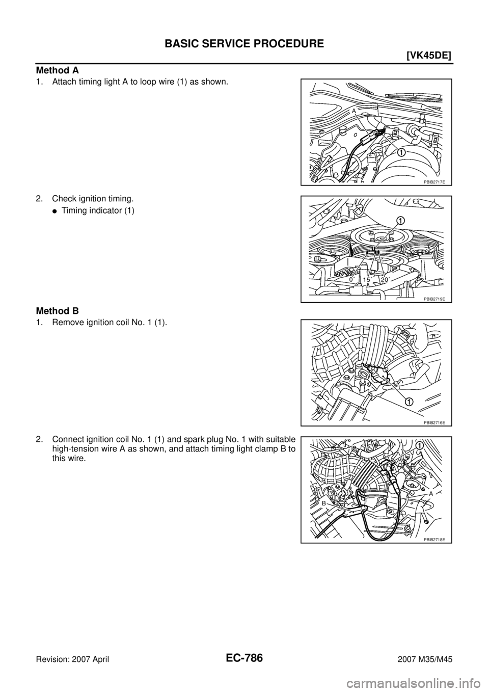
Method A
1. Attach timing light A to loop wire (1) as shown.
2. Check ignition timing.
�Timing indicator (1)
Method B
1. Remove ignition coil No. 1 (1).
2. Connect ignition coil No. 1 (1) and spark plug No. 1 with suitable
high-tension wire A as shown, and attach timing light clamp B to
this wire.
PBIB2717E
PBIB2719E
PBIB2716E
PBIB2718E
Page 2334 of 4647
![INFINITI M35 2007 Factory Service Manual TROUBLE DIAGNOSIS
EC-805
[VK45DE]
C
D
E
F
G
H
I
J
K
L
MA
EC
Revision: 2007 April2007 M35/M45
Engine Control Component Parts LocationNBS005AI
1. IPDM E/R 2. ICC brake hold relay
(ICC models only)3. Bat](/manual-img/42/57024/w960_57024-2333.png "INFINITI M35 2007 Factory Service Manual TROUBLE DIAGNOSIS
EC-805
[VK45DE]
C
D
E
F
G
H
I
J
K
L
MA
EC
Revision: 2007 April2007 M35/M45
Engine Control Component Parts LocationNBS005AI
1. IPDM E/R 2. ICC brake hold relay
(ICC models only)3. Bat")
TROUBLE DIAGNOSIS
EC-805
[VK45DE]
C
D
E
F
G
H
I
J
K
L
MA
EC
Revision: 2007 April2007 M35/M45
Engine Control Component Parts LocationNBS005AI
1. IPDM E/R 2. ICC brake hold relay
(ICC models only)3. Battery current sensor
4. Cooling fan relay 5. Refrigerant pressure sensor 6. Intake valve timing control position
sensor (bank 2)
7. Vacuum tank 8. Cooling fan motor-2 9. Intake valve timing control solenoid
valve (bank 2)
10. Cooling fan control module 11. Electric throttle control actuator 12. Intake valve timing control solenoid
valve (bank 1)
13. Cooling fan motor-1 14. Intake valve timing control position
sensor (bank 1)15. Camshaft position sensor (PHASE)
16. Mass air flow sensor
(with intake air temperature sensor)17. Ignition coil (with power transistor)
and spark plug (bank 1)18. VIAS control solenoid valve
19. Fuel injector (bank 1) 20. Engine coolant temperature sensor 21. Power valve actuator
22. Knock sensor (bank 1) 23. Knock sensor (bank 2) 24. Fuel injector (bank 2)
25. EVAP canister purge volume control
solenoid valve26. EVAP service port 27. Ignition coil (with power transistor)
and spark plug (bank 2)
PBIB2674E
![INFINITI M35 2007 Factory Service Manual IGNITION SIGNAL
EC-703
[VQ35DE]
C
D
E
F
G
H
I
J
K
L
MA
EC
Revision: 2007 April2007 M35/M45
3. Check resistance between condenser terminals 1 and 2.
Removal and InstallationNBS0057S
IGNITION COIL WITH](/manual-img/42/57024/w960_57024-2231.png "INFINITI M35 2007 Factory Service Manual IGNITION SIGNAL
EC-703
[VQ35DE]
C
D
E
F
G
H
I
J
K
L
MA
EC
Revision: 2007 April2007 M35/M45
3. Check resistance between condenser terminals 1 and 2.
Removal and InstallationNBS0057S
IGNITION COIL WITH")