Page 3076 of 4647
FRONT FINAL DRIVE ASSEMBLY
FFD-21
C
E
F
G
H
I
J
K
L
MA
B
FFD
Revision: 2007 April2007 M35/M45
7. Remove differential case assembly from gear carrier.
8. Remove side oil seal (right side) from side retainer.
9. Remove side bearing outer race with puller.
10. Remove O-ring from gear carrier.
11. Remove side oil seal (left side) from gear carrier.
12. Remove side bearing outer race with puller.
PDIA0671E
PDIA0672E
Tool number A: KV381054S0 (J-34286)
PDIA0796J
Tool number A: KV381054S0 (J-34286)
PDIA0797J
Page 3077 of 4647
FFD-22
FRONT FINAL DRIVE ASSEMBLY
Revision: 2007 April2007 M35/M45
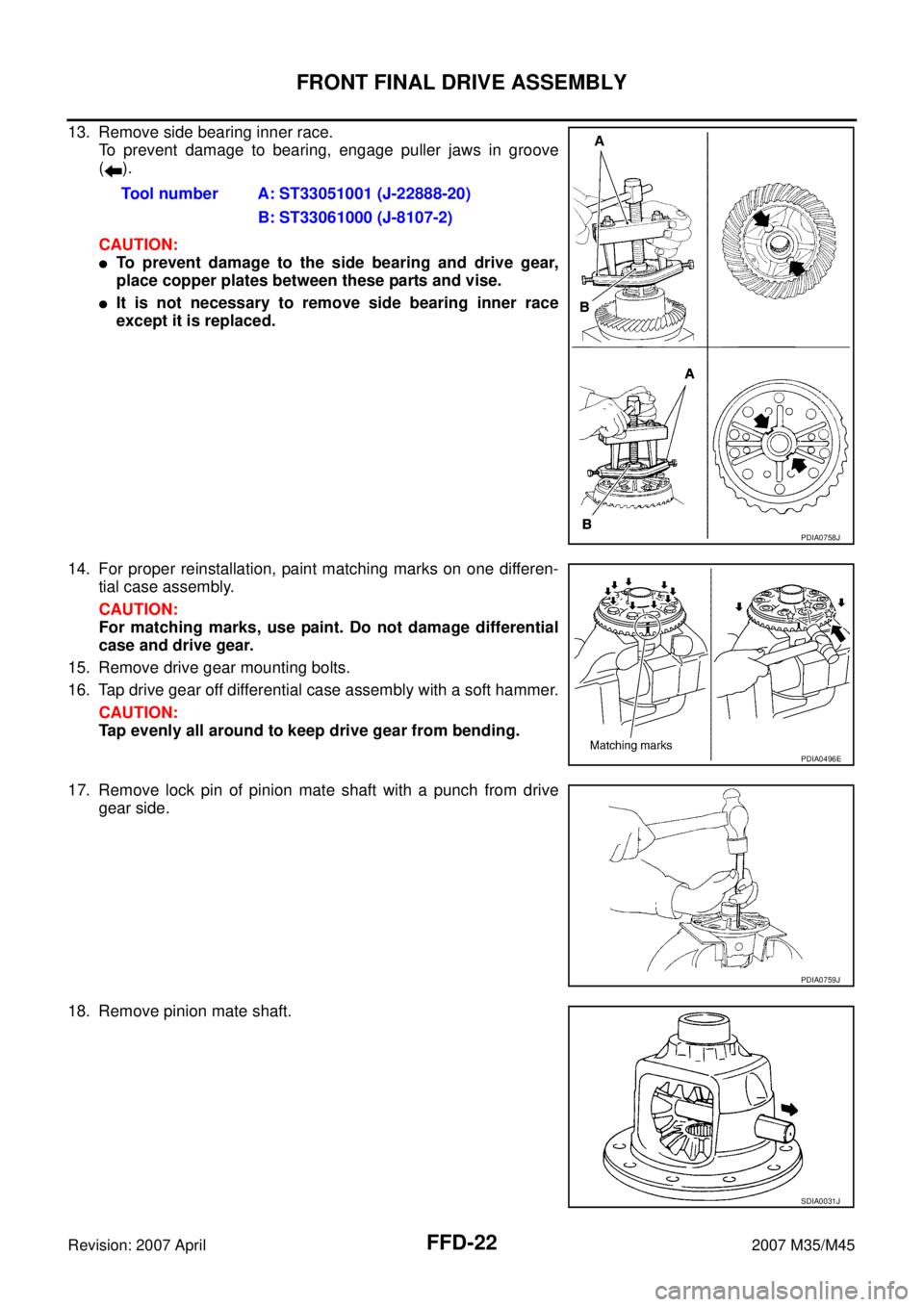
13. Remove side bearing inner race.
To prevent damage to bearing, engage puller jaws in groove
().
CAUTION:
�To prevent damage to the side bearing and drive gear,
place copper plates between these parts and vise.
�It is not necessary to remove side bearing inner race
except it is replaced.
14. For proper reinstallation, paint matching marks on one differen-
tial case assembly.
CAUTION:
For matching marks, use paint. Do not damage differential
case and drive gear.
15. Remove drive gear mounting bolts.
16. Tap drive gear off differential case assembly with a soft hammer.
CAUTION:
Tap evenly all around to keep drive gear from bending.
17. Remove lock pin of pinion mate shaft with a punch from drive
gear side.
18. Remove pinion mate shaft.Tool number A: ST33051001 (J-22888-20)
B: ST33061000 (J-8107-2)
PDIA0758J
PDIA0496E
PDIA0759J
SDIA0031J
Page 3078 of 4647
FRONT FINAL DRIVE ASSEMBLY
FFD-23
C
E
F
G
H
I
J
K
L
MA
B
FFD
Revision: 2007 April2007 M35/M45
19. Turn pinion mate gear, then remove pinion mate gears, pinion
mate thrust washers, side gears and side gear thrust washers
from differential case.
Drive Pinion Assembly
1. Remove differential assembly. Refer to FFD-20, "Differential Assembly" .
2. Remove drive pinion lock nut with a flange wrench.
3. Put matching mark (B) on the end of drive pinion. The matching
mark should be in line with the matching mark (A) on companion
flange (1).
CAUTION:
For matching mark, use paint. Do not damage companion
flange and drive pinion.
NOTE:
The matching mark (A) on the final drive companion flange (1)
indicates the maximum vertical runout position.
When replacing companion flange, matching mark is not neces-
sary.
4. Remove companion flange using the suitable puller.
SDIA0032J
PDIA0798J
PDIA0799J
SDIA1132E
Page 3079 of 4647

FFD-24
FRONT FINAL DRIVE ASSEMBLY
Revision: 2007 April2007 M35/M45
5. Press drive pinion assembly out of gear carrier.
CAUTION:
Do not drop drive pinion assembly.
6. Remove front oil seal.
7. Remove pinion front bearing inner race.
8. Remove drive pinion bearing adjusting washer and drive pinion
adjusting washer.
9. Remove pinion rear bearing inner race and pinion height adjust-
ing washer with replacer.
10. Tap pinion front/rear bearing outer races uniformly a brass rod or
equivalent to removed.
CAUTION:
Be careful not to damage gear carrier.
INSPECTION AFTER DISASSEMBLY
Clean up the disassembled parts. Then, inspect if the parts are worn or damaged. If so, follow the measures
below.
PDIA0800J
Tool number A: ST30031000 (J-22912-01)
PDIA0801J
PDIA0677E
Content Conditions and Measures
Hypoid gear
�If the gear teeth do not mesh or line-up correctly, determine the cause and adjust or replace as nec-
essary.
�If the gears are worn, cracked, damaged, pitted or chipped (by friction) noticeably, replace with new
drive gear and drive pinion as a set.
Bearing
�If any chipped (by friction), pitted, worn, rusted or scratched mark, or unusual noise from the bearing
is observed, replace as a bearing assembly (as a new set).
Side gear and Pinion mate
gear
�If any cracks or damage on the surface of the tooth is found, replace.
�If any worn or chipped mark on the contact sides of the thrust washer is found, replace.
Side gear thrust washer and
pinion mate thrust washer
�If it is chipped (by friction), damaged, or unusually worn, replace.
Oil seal
�Whenever disassembled, replace.
�If wear, deterioration of adherence (sealing force lips), or damage is detected on the lips, replace
them.
Differential case
�If any wear or crack on the contact sides of the differential case is found, replace.
Companion flange
�If any chipped mark (about 0.1 mm, 0.004 in) or other damage on the contact sides of the lips of the
companion flange is found, replace.
Page 3080 of 4647

Differential Side Gear Clearance
�Assemble the diffe")
FRONT FINAL DRIVE ASSEMBLY
FFD-25
C
E
F
G
H
I
J
K
L
MA
B
FFD
Revision: 2007 April2007 M35/M45
ADJUSTMENT AND SELECTION OF ADJUSTING WASHERS (SHIMS)
Differential Side Gear Clearance
�Assemble the differential parts if they are disassembled. Refer to FFD-30, "Differential Assembly" .
1. Place differential case straight up so that side gear to be mea-
sured comes upward.
2. Using feeler gauge, measure the clearance between side gear
back and differential case at 3 different points, while rotating
side gear. Average the 3 readings, and then measure the clear-
ance of the other side as well.
CAUTION:
To prevent side gear from tilting, insert feeler gauges with
the same thickness from both sides.
3. If the back clearance is outside the specification, use a thicker/
thinner side gear thrust washer to adjust. Refer to FFD-35, "
Side
Gear Thrust Washer" .
CAUTION:
Select a side gear thrust washer for right and left individu-
ally.
Side Bearing Preload
1. Make sure all parts are clean. Also, make sure the bearings are well lubricated with gear oil.
2. Press-fit side bearing outer race into side retainer with tool.
CAUTION:
�At first, using a hammer, tap bearing outer race until it
becomes flat to side retainer.
�Do not reuse side bearing outer race.
PDIA0460E
Side gear back clearance specification:
0.2 mm (0.008 in) or less.
(Each gear should rotate smoothly without excessive
resistance during differential motion.)
When the back clearance is large:
Use a thicker thrust washer.
When the back clearance is small:
Use a thinner thrust washer.
PDIA0576E
Tool number A: ST30611000 (J-25742-1)
B: KV31103000 (J-38982)
PDIA0811J
Page 3081 of 4647
FFD-26
FRONT FINAL DRIVE ASSEMBLY
Revision: 2007 April2007 M35/M45
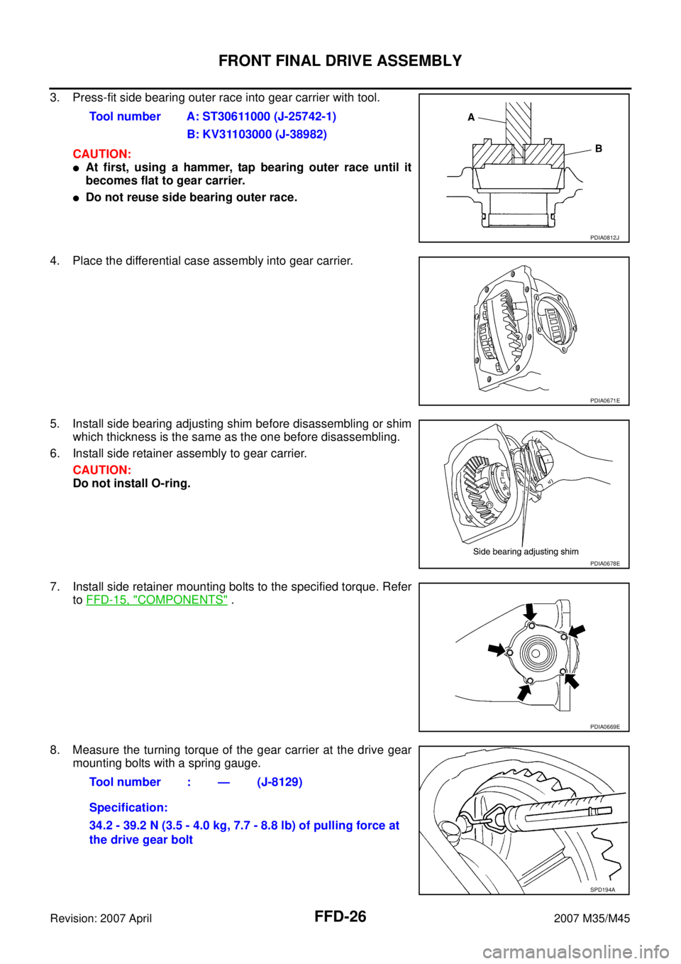
3. Press-fit side bearing outer race into gear carrier with tool.
CAUTION:
�At first, using a hammer, tap bearing outer race until it
becomes flat to gear carrier.
�Do not reuse side bearing outer race.
4. Place the differential case assembly into gear carrier.
5. Install side bearing adjusting shim before disassembling or shim
which thickness is the same as the one before disassembling.
6. Install side retainer assembly to gear carrier.
CAUTION:
Do not install O-ring.
7. Install side retainer mounting bolts to the specified torque. Refer
to FFD-15, "
COMPONENTS" .
8. Measure the turning torque of the gear carrier at the drive gear
mounting bolts with a spring gauge.Tool number A: ST30611000 (J-25742-1)
B: KV31103000 (J-38982)
PDIA0812J
PDIA0671E
PDIA0678E
PDIA0669E
Tool number : — (J-8129)
Specification:
34.2 - 39.2 N (3.5 - 4.0 kg, 7.7 - 8.8 lb) of pulling force at
the drive gear bolt
SPD194A
Page 3085 of 4647
.
NOTE:
When reusing drive pinion, align the matching mark (B) of drive
pinion with the matching mark")
FFD-30
FRONT FINAL DRIVE ASSEMBLY
Revision: 2007 April2007 M35/M45
10. Install companion flange (1).
NOTE:
When reusing drive pinion, align the matching mark (B) of drive
pinion with the matching mark (A) of companion flange, and then
install companion flange (1).
11. Apply anti-corrosion oil to the thread and seat of new drive pin-
ion lock nut, and temporarily tighten drive pinion lock nut to drive
pinion.
CAUTION:
Do not reuse drive pinion lock nut.
12. Tighten to drive pinion lock nut, while adjust pinion bearing pre-
load torque.
CAUTION:
�Adjust to the lower limit of the drive pinion lock nut tight-
ening torque first.
�After adjustment, rotate drive pinion back and forth 2 to 3
times to check for unusual noise, rotation malfunction,
and other malfunctions.
13. Install differential case assembly. Refer to FFD-30, "
Differential
Assembly" .
CAUTION:
Do not install carrier cover yet.
14. Check and adjust drive gear runout, tooth contact, drive gear to drive pinion backlash, and companion
flange runout. Refer to FFD-17, "
Drive Gear Runout" , FFD-17, "Tooth Contact" , FFD-19, "Backlash" ,
FFD-19, "
Companion Flange Runout" .
Recheck above items. Readjust the above description, if necessary.
15. Check total preload torque. Refer to FFD-16, "
Total Preload Torque" .
16. Install carrier cover. Refer to FFD-30, "
Differential Assembly" .
Differential Assembly
1. Install side gear thrust washers with the same thickness as the
ones installed prior to disassembly or reinstall the old ones on
the side gears.
PDIA0799J
Tool number A: ST3127S000 (J-25765-A)
Drive pinion lock nut tightening torque:
127.4 - 245.0 N·m (13.0 - 25.0 kg-m, 94 - 181 ft-lb)
Pinion bearing preload:
0.78 - 1.57 N·m (0.08 - 0.16 kg-m, 7 - 13 in-lb)
PDIA0802J
SDIA0193J
Page 3086 of 4647

FRONT FINAL DRIVE ASSEMBLY
FFD-31
C
E
F
G
H
I
J
K
L
MA
B
FFD
Revision: 2007 April2007 M35/M45
2. Install side gears and thrust washers into differential case.
CAUTION:
�Do not reuse circular clip.
�Make sure that the circular clip is installed to side gear
(side retainer side).
3. Align 2 pinion mate gears in diagonally opposite positions, then
rotate and install them into differential case after installing thrust
washer to pinion mate gear.
4. Align the lock pin holes on differential case with shaft, and install
pinion mate shaft.
5. Measure side gear end play. If necessary, select the appropriate
side gear thrust washers. Refer to FFD-25, "
Differential Side
Gear Clearance" .
6. Drive a lock pin into pinion mate shaft, using a punch.
Make sure lock pin is flush with differential case.
CAUTION:
Do not reuse lock pin.
7. Align the matching mark of drive gear with the mark of differen-
tial case, then place drive gear.
8. Apply thread locking sealant into the thread hole of drive gear.
�Use Genuine Medium Strength Thread Locking Sealant or
equivalent. Refer to GI-47, "
Recommended Chemical
Products and Sealants" .
CAUTION:
Drive gear back and threaded holes shall be cleaned and
degreased sufficiently.
SDIA2025E
SDIA0195J
SPD030
SDIA2593E
SDIA2594E
 from side ret")