Page 4102 of 4647
REAR FINAL DRIVE ASSEMBLY
RFD-33
C
E
F
G
H
I
J
K
L
MA
B
RFD
Revision: 2007 April2007 M35/M45
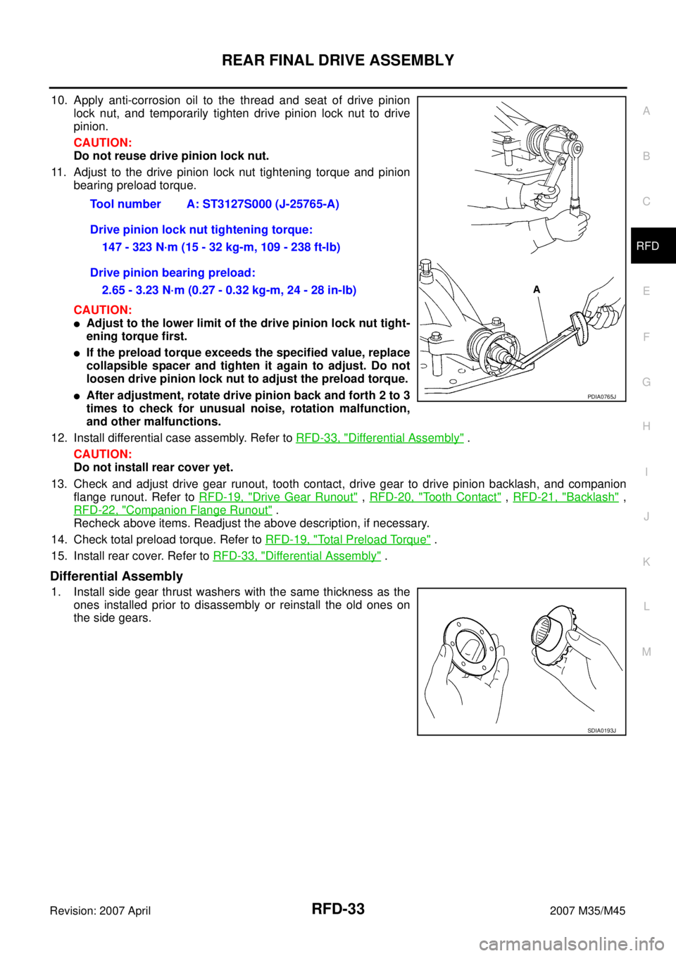
10. Apply anti-corrosion oil to the thread and seat of drive pinion
lock nut, and temporarily tighten drive pinion lock nut to drive
pinion.
CAUTION:
Do not reuse drive pinion lock nut.
11. Adjust to the drive pinion lock nut tightening torque and pinion
bearing preload torque.
CAUTION:
�Adjust to the lower limit of the drive pinion lock nut tight-
ening torque first.
�If the preload torque exceeds the specified value, replace
collapsible spacer and tighten it again to adjust. Do not
loosen drive pinion lock nut to adjust the preload torque.
�After adjustment, rotate drive pinion back and forth 2 to 3
times to check for unusual noise, rotation malfunction,
and other malfunctions.
12. Install differential case assembly. Refer to RFD-33, "
Differential Assembly" .
CAUTION:
Do not install rear cover yet.
13. Check and adjust drive gear runout, tooth contact, drive gear to drive pinion backlash, and companion
flange runout. Refer to RFD-19, "
Drive Gear Runout" , RFD-20, "Tooth Contact" , RFD-21, "Backlash" ,
RFD-22, "
Companion Flange Runout" .
Recheck above items. Readjust the above description, if necessary.
14. Check total preload torque. Refer to RFD-19, "
Total Preload Torque" .
15. Install rear cover. Refer to RFD-33, "
Differential Assembly" .
Differential Assembly
1. Install side gear thrust washers with the same thickness as the
ones installed prior to disassembly or reinstall the old ones on
the side gears.Tool number A: ST3127S000 (J-25765-A)
Drive pinion lock nut tightening torque:
147 - 323 N·m (15 - 32 kg-m, 109 - 238 ft-lb)
Drive pinion bearing preload:
2.65 - 3.23 N·m (0.27 - 0.32 kg-m, 24 - 28 in-lb)
PDIA0765J
SDIA0193J
Page 4103 of 4647
RFD-34
REAR FINAL DRIVE ASSEMBLY
Revision: 2007 April2007 M35/M45
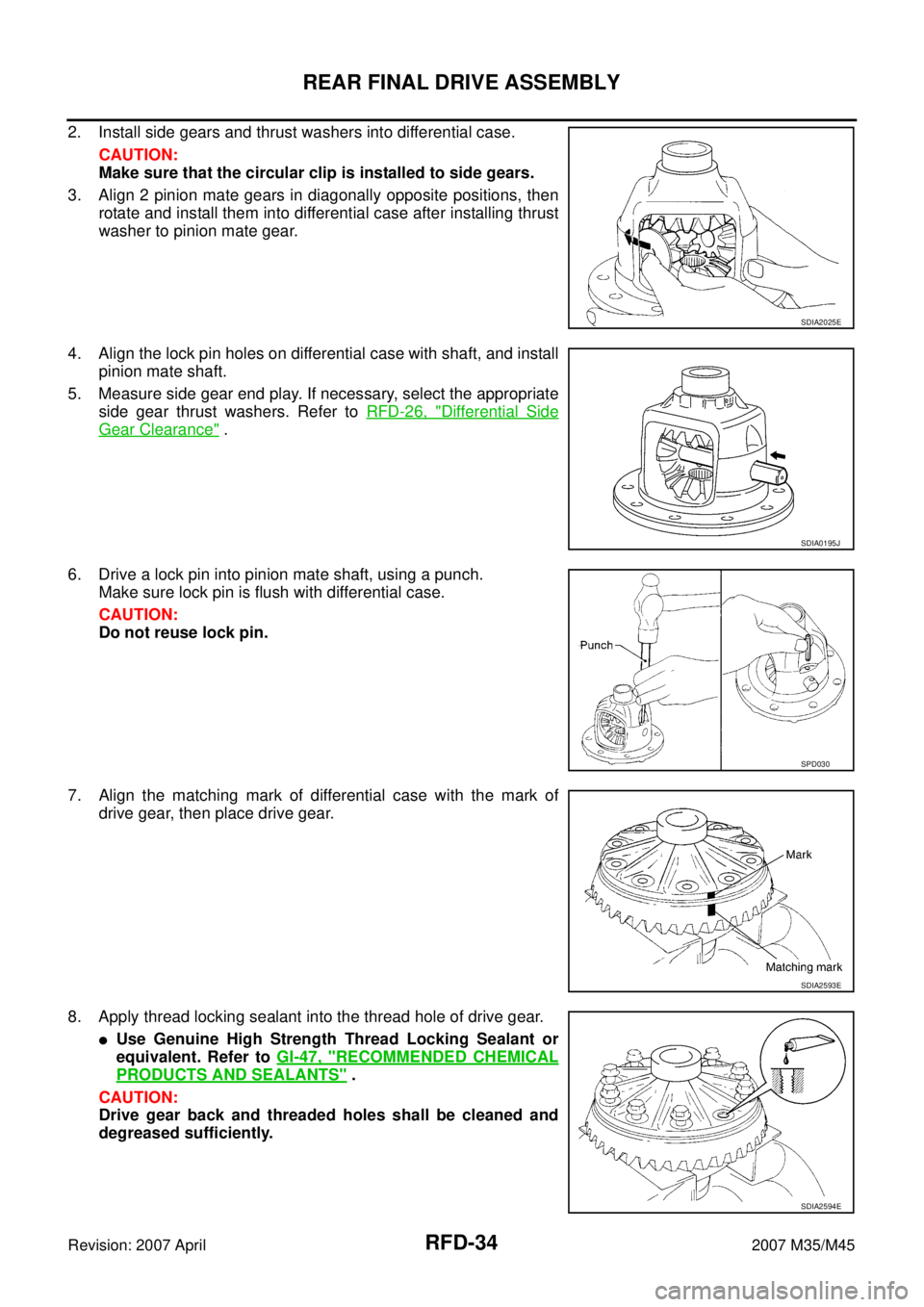
2. Install side gears and thrust washers into differential case.
CAUTION:
Make sure that the circular clip is installed to side gears.
3. Align 2 pinion mate gears in diagonally opposite positions, then
rotate and install them into differential case after installing thrust
washer to pinion mate gear.
4. Align the lock pin holes on differential case with shaft, and install
pinion mate shaft.
5. Measure side gear end play. If necessary, select the appropriate
side gear thrust washers. Refer to RFD-26, "
Differential Side
Gear Clearance" .
6. Drive a lock pin into pinion mate shaft, using a punch.
Make sure lock pin is flush with differential case.
CAUTION:
Do not reuse lock pin.
7. Align the matching mark of differential case with the mark of
drive gear, then place drive gear.
8. Apply thread locking sealant into the thread hole of drive gear.
�Use Genuine High Strength Thread Locking Sealant or
equivalent. Refer to GI-47, "
RECOMMENDED CHEMICAL
PRODUCTS AND SEALANTS" .
CAUTION:
Drive gear back and threaded holes shall be cleaned and
degreased sufficiently.
SDIA2025E
SDIA0195J
SPD030
SDIA2593E
SDIA2594E
Page 4104 of 4647
REAR FINAL DRIVE ASSEMBLY
RFD-35
C
E
F
G
H
I
J
K
L
MA
B
RFD
Revision: 2007 April2007 M35/M45
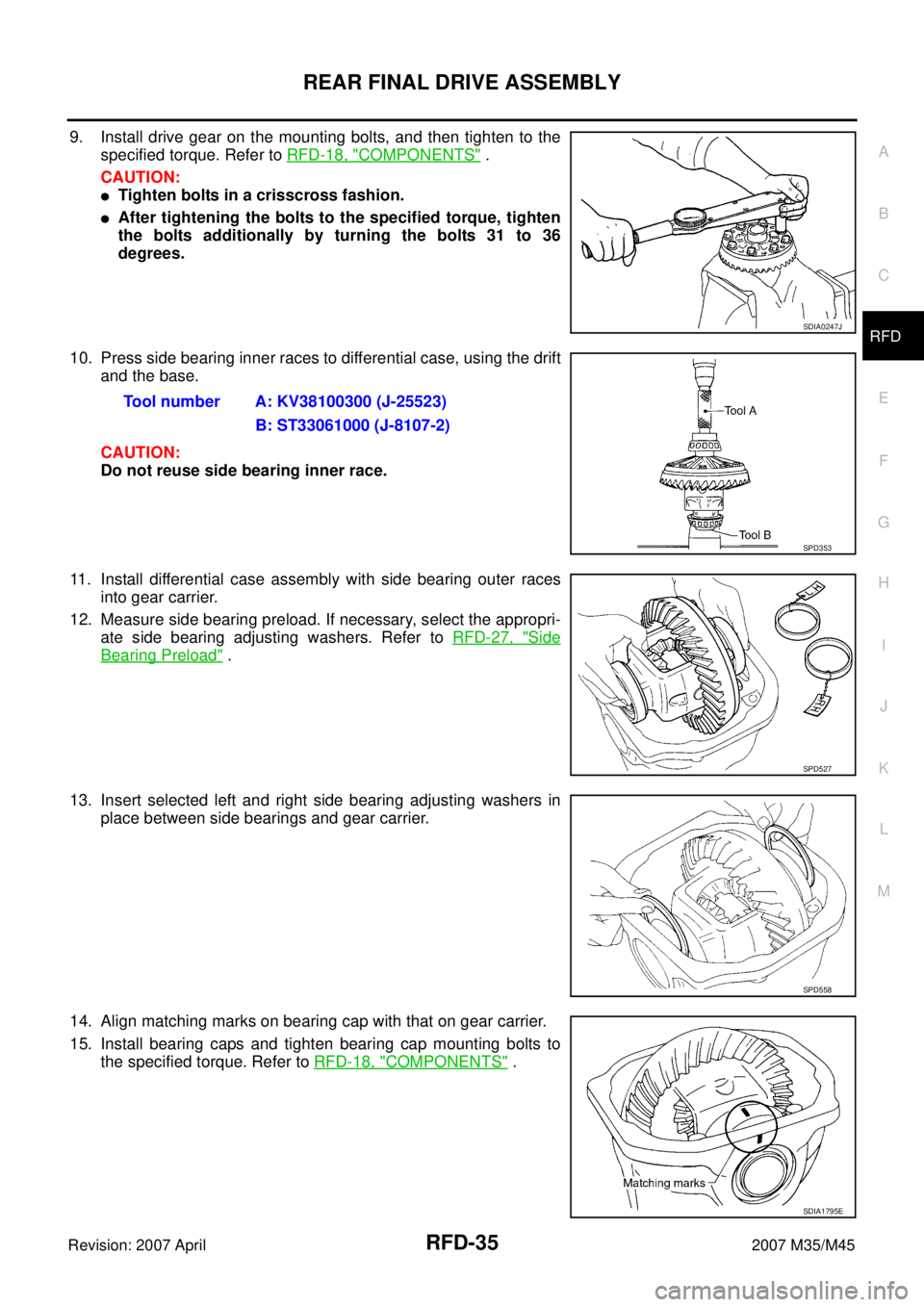
9. Install drive gear on the mounting bolts, and then tighten to the
specified torque. Refer to RFD-18, "
COMPONENTS" .
CAUTION:
�Tighten bolts in a crisscross fashion.
�After tightening the bolts to the specified torque, tighten
the bolts additionally by turning the bolts 31 to 36
degrees.
10. Press side bearing inner races to differential case, using the drift
and the base.
CAUTION:
Do not reuse side bearing inner race.
11. Install differential case assembly with side bearing outer races
into gear carrier.
12. Measure side bearing preload. If necessary, select the appropri-
ate side bearing adjusting washers. Refer to RFD-27, "
Side
Bearing Preload" .
13. Insert selected left and right side bearing adjusting washers in
place between side bearings and gear carrier.
14. Align matching marks on bearing cap with that on gear carrier.
15. Install bearing caps and tighten bearing cap mounting bolts to
the specified torque. Refer to RFD-18, "
COMPONENTS" .
SDIA0247J
Tool number A: KV38100300 (J-25523)
B: ST33061000 (J-8107-2)
SPD353
SPD527
SPD558
SDIA1795E
Page 4106 of 4647
SERVICE DATA AND SPECIFICATIONS (SDS)
RFD-37
C
E
F
G
H
I
J
K
L
MA
B
RFD
Revision: 2007 April2007 M35/M45
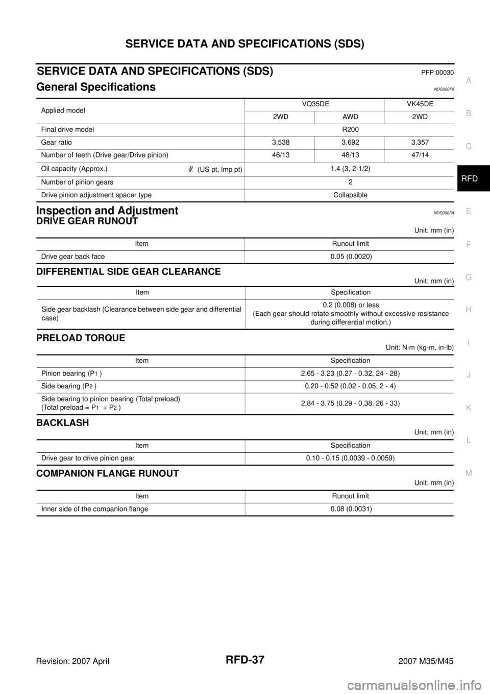
SERVICE DATA AND SPECIFICATIONS (SDS)PFP:00030
General SpecificationsNDS000F9
Inspection and AdjustmentNDS000FA
DRIVE GEAR RUNOUT
Unit: mm (in)
DIFFERENTIAL SIDE GEAR CLEARANCE
Unit: mm (in)
PRELOAD TORQUE
Unit: N·m (kg-m, in-lb)
BACKLASH
Unit: mm (in)
COMPANION FLANGE RUNOUT
Unit: mm (in) Applied modelVQ35DE VK45DE
2WD AWD 2WD
Final drive modelR200
Gear ratio 3.538 3.692 3.357
Number of teeth (Drive gear/Drive pinion) 46/13 48/13 47/14
Oil capacity (Approx.)
(US pt, lmp pt)1.4 (3, 2-1/2)
Number of pinion gears2
Drive pinion adjustment spacer type Collapsible
Item Runout limit
Drive gear back face 0.05 (0.0020)
Item Specification
Side gear backlash (Clearance between side gear and differential
case)0.2 (0.008) or less
(Each gear should rotate smoothly without excessive resistance
during differential motion.)
Item Specification
Pinion bearing (P
1 ) 2.65 - 3.23 (0.27 - 0.32, 24 - 28)
Side bearing (P
2 ) 0.20 - 0.52 (0.02 - 0.05, 2 - 4)
Side bearing to pinion bearing (Total preload)
(Total preload = P
1 + P2 )2.84 - 3.75 (0.29 - 0.38, 26 - 33)
Item Specification
Drive gear to drive pinion gear 0.10 - 0.15 (0.0039 - 0.0059)
Item Runout limit
Inner side of the companion flange 0.08 (0.0031)
Page 4111 of 4647
RSU-4
NOISE, VIBRATION AND HARSHNESS (NVH) TROUBLESHOOTING
Revision: 2007 April2007 M35/M45
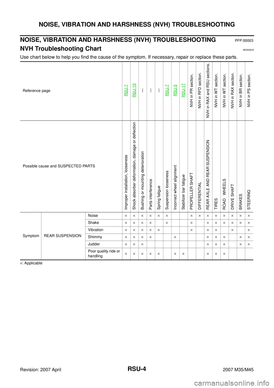
NOISE, VIBRATION AND HARSHNESS (NVH) TROUBLESHOOTINGPFP:00003
NVH Troubleshooting ChartNES000J5
Use chart below to help you find the cause of the symptom. If necessary, repair or replace these parts.
×: ApplicableReference page
RSU-7RSU-10
—
—
—
RSU-7RSU-5RSU-17
NVH in PR section.
NVH in RFD section.
NVH in RAX and RSU sections.
NVH in WT section.
NVH in WT section.
NVH in RAX section.
NVH in BR section.
NVH in PS section.
Possible cause and SUSPECTED PARTS
Improper installation, looseness
Shock absorber deformation, damage or deflection
Bushing or mounting deterioration
Parts interference
Spring fatigue
Suspension looseness
Incorrect wheel alignment
Stabilizer bar fatigue
PROPELLER SHAFT
DIFFERENTIAL
REAR AXLE AND REAR SUSPENSION
TIRES
ROAD WHEELS
DRIVE SHAFT
BRAKES
STEERING
Symptom REAR SUSPENSIONNoise×××××× ××××××××
Shake×××× × × ××××××
Vibration××××× × ×× × ×
Shimmy×××× × ××× ××
Judder ××× ××× ××
Poor quality ride or
handling××××× ×× ×××
Page 4554 of 4647
NOISE, VIBRATION AND HARSHNESS (NVH) TROUBLESHOOTING
WT-5
C
D
F
G
H
I
J
K
L
MA
B
WT
Revision: 2007 April2007 M35/M45
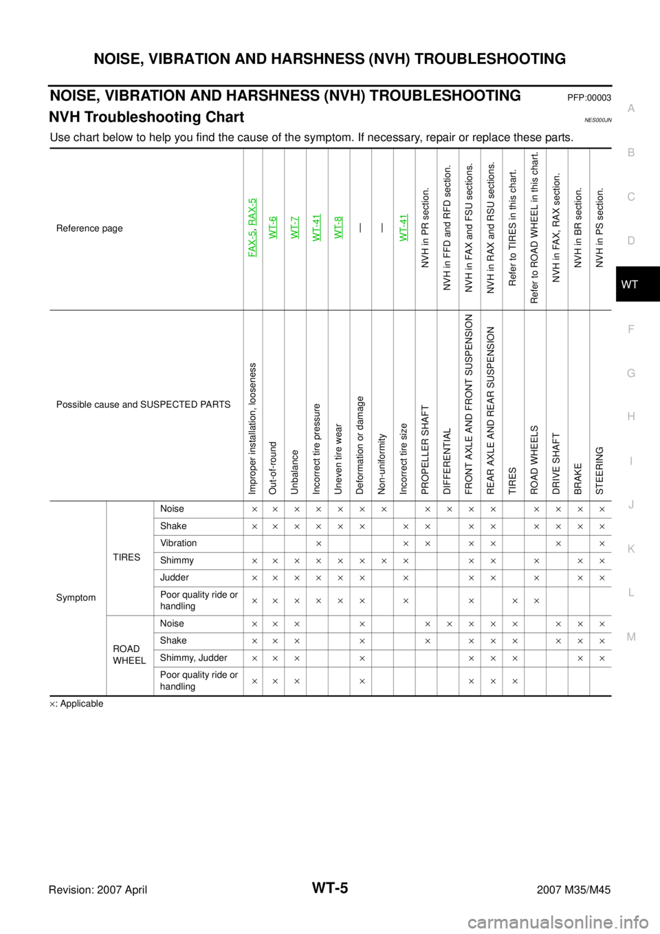
NOISE, VIBRATION AND HARSHNESS (NVH) TROUBLESHOOTINGPFP:00003
NVH Troubleshooting ChartNES000JN
Use chart below to help you find the cause of the symptom. If necessary, repair or replace these parts.
×: ApplicableReference page
FAX-5
, RAX-5WT-6WT-7WT-41WT-8—
—
WT-41
NVH in PR section.
NVH in FFD and RFD section.
NVH in FAX and FSU sections.
NVH in RAX and RSU sections.
Refer to TIRES in this chart.
Refer to ROAD WHEEL in this chart.
NVH in FAX, RAX section.
NVH in BR section.
NVH in PS section.
Possible cause and SUSPECTED PARTS
Improper installation, looseness
Out-of-round
Unbalance
Incorrect tire pressure
Uneven tire wear
Deformation or damage
Non-uniformity
Incorrect tire size
PROPELLER SHAFT
DIFFERENTIAL
FRONT AXLE AND FRONT SUSPENSION
REAR AXLE AND REAR SUSPENSION
TIRES
ROAD WHEELS
DRIVE SHAFT
BRAKE
STEERING
SymptomTIRESNoise××××××× ×××× ××××
Shake×××××× ×× ×× ××××
Vibration×××××××
Shimmy×××××××× ×× × ××
Judder×××××× × ×× × ××
Poor quality ride or
handling×××××× × × ××
ROAD
WHEELNoise××× × ××××× ×××
Shake××× × × ××× ×××
Shimmy, Judder××× × ××× ××
Poor quality ride or
handling××× × ×××