Page 4011 of 4647

PS-30
POWER STEERING OIL PUMP
Revision: 2007 April2007 M35/M45
POWER STEERING OIL PUMPPFP:49110
On-Vehicle Inspection and ServiceNGS000DE
CHECKING RELIEF OIL PRESSURE
CAUTION:
Make sure that belt tension is normal before starting the following procedure.
1. Connect the hydraulic pressure gauge [SST] between oil pump
discharge connector and high-pressure hose. Bleed air from the
hydraulic circuit while opening valve fully. Refer to PS-8, "
Air
Bleeding Hydraulic System" .
2. Start engine. Run engine until oil temperature reaches 50 to
80°C (122 to 176°F).
CAUTION:
�Leave the valve of the hydraulic pressure gauge [SST]
fully open while starting and running engine. If engine is
started with the valve closed, the hydraulic pressure in
oil pump goes up to the relief pressure along with
unusual increase of oil temperature.
�Be sure to keep hose clear of belts and other parts when
engine is started.
3. Fully close the hydraulic pressure gauge [SST] valve with
engine at idle and measure the relief oil pressure.
CAUTION:
Never keep valve closed for 10 seconds or longer.
4. Open the valve slowly after measuring. Repair oil pump if the
relief oil pressure is outside the standard. Refer to PS-31, "
Dis-
assembly and Assembly (Models with VK45DE)" , PS-35, "Disassembly and Assembly (Models with
VQ35DE)" .
5. After inspection, disconnect the hydraulic pressure gauge [SST] from hydraulic circuit, then add fluid and
bleed air. Refer to PS-8, "
Air Bleeding Hydraulic System" .
Removal and InstallationNGS000DF
REMOVAL
1. Drain power steering fluid from reservoir tank.
2. Remove undercover from vehicle with a power tool.
3. Loosen drive belt. Refer to EM-16, "
DRIVE BELTS" (VQ35DE), EM-174, "DRIVE BELTS" (VK45DE).
4. Remove drive belt from oil pump pulley.
5. Remove piping of high pressure and low pressure (drain fluid from their pipings). Refer to PS-39,
"HYDRAULIC LINE" .
6. Remove power steering oil pump mounting bolts, and then remove power steering oil pump. Refer to PS-
39, "Removal and Installation" .
INSTALLATION
Installation is the reverse order of removal. For tightening torque, refer to PS-39, "HYDRAULIC LINE" .
�Perform the following procedure after installing.
–Adjust belt tension (VQ35DE). Refer to EM-16, "Tension Adjustment" .
–About the installation of VK45DE drive belt, refer to EM-174, "Tension Adjustment" .
–Bleed air. Refer to PS-8, "Air Bleeding Hydraulic System" . Relief oil pressure:
8,520 - 9,320 kpa (86.9 - 95.1 kg/cm
2 , 1,235 - 1,351 psi)
SGIA0915E
Page 4015 of 4647
PS-34
POWER STEERING OIL PUMP
Revision: 2007 April2007 M35/M45
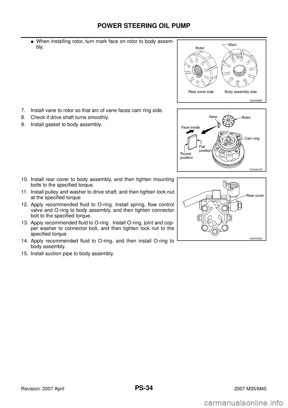
�When installing rotor, turn mark face on rotor to body assem-
bly.
7. Install vane to rotor so that arc of vane faces cam ring side.
8. Check if drive shaft turns smoothly.
9. Install gasket to body assembly.
10. Install rear cover to body assembly, and then tighten mounting
bolts to the specified torque.
11. Install pulley and washer to drive shaft, and then tighten lock nut
at the specified torque.
12. Apply recommended fluid to O-ring. Install spring, flow control
valve and O-ring to body assembly, and then tighten connector
bolt to the specified torque.
13. Apply recommended fluid to O-ring . Install O-ring, joint and cop-
per washer to connector bolt, and then tighten lock nut to the
specified torque.
14. Apply recommended fluid to O-ring, and then install O-ring to
body assembly.
15. Install suction pipe to body assembly.
SGIA0989E
SGIA0613E
SGIA0425E
Page 4018 of 4647

POWER STEERING OIL PUMP
PS-37
C
D
E
F
H
I
J
K
L
MA
B
PS
Revision: 2007 April2007 M35/M45
ASSEMBLY
NOTE:
Secure oil pump in a vise if necessary.
CAUTION:
Use copper plates when securing in a vise.
1. Apply recommended grease to oil seal lips. Apply recommended
fluid to around oil seal, and then install oil seal to body assembly
using the drift [SST].
2. Install bracket to body assembly, and then tighten mounting
bolts to the specified torque.
3. If dowel pin has been removed, insert it into body assembly by
hand. If cannot be inserted by hand, lightly tap with a hammer.
4. Install flow control valve A, flow control valve spring and flow
control valve B assembly as shown in the figure.
5. Install front side plate (3) with dowel pin (2) on flow control valve
A (1) side as shown in the figure aligning with front side plate
cutout (A) to body assembly (4).
6. Install cam ring as shown in the figure.
7. Install pulley to body assembly.
CAUTION:
Do not damage oil seal when installing pulley.
SGIA0527E
SGIA0526E
SGIA1189E
SGIA0612E
Page 4019 of 4647

PS-38
POWER STEERING OIL PUMP
Revision: 2007 April2007 M35/M45
8. Install rotor so that mark faces body assembly, and then install it
to pulley shaft.
9. Install vane to rotor so that arc of vane faces cam ring side.
10. Install rotor snap ring to slit of pulley shaft using a hammer and a
10 mm (0.39 in) socket.
CAUTION:
�Do not damage rotor and pulley shaft.
�Power steering oil pump assembly must be replaced if
rotor is damaged.
11. Install rear side plate with dowel pin A on flow control valve A
side as shown in the figure aligning with rear side plate cutout B
to cartridge.
12. Apply recommended fluid to O-ring, and then install O-ring to
body assembly.
13. Apply recommended fluid to O-ring, and then install O-ring to
rear side plate.
14. Apply recommended fluid to Teflon ring, and then install Teflon
ring to rear side plate.
15. Install rear cover to body assembly, and then tighten mounting
bolts to the specified torque.
16. Apply recommended fluid to O-ring, and then install O-ring to body assembly.
17. Install suction pipe to body assembly.
SGIA0989E
SGIA0613E
SGIA0063E
SGIA0530E
Page 4025 of 4647
PS-44
HYDRAULIC LINE
Revision: 2007 April2007 M35/M45
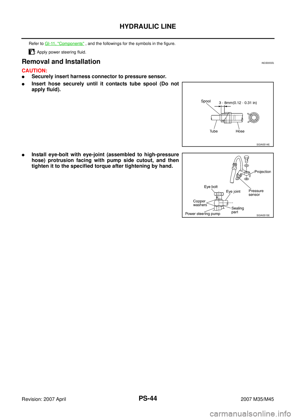
Removal and InstallationNGS000DL
CAUTION:
�Securely insert harness connector to pressure sensor.
�Insert hose securely until it contacts tube spool (Do not
apply fluid).
�Install eye-bolt with eye-joint (assembled to high-pressure
hose) protrusion facing with pump side cutout, and then
tighten it to the specified torque after tightening by hand.
Refer to GI-11, "Components" , and the followings for the symbols in the figure.
: Apply power steering fluid.
SGIA0514E
SGIA0515E
Page 4027 of 4647

Revision: 2007 April2007 M35/M45
Steering GearNGS000DP
STEERING OUTER SOCKET AND INNER SOCKET
RACK STROKE
RACK SLIDING FORCE
Oil PumpNGS000DR
Steering Fluid")
PS-46
SERVICE DATA AND SPECIFICATIONS (SDS)
Revision: 2007 April2007 M35/M45
Steering GearNGS000DP
STEERING OUTER SOCKET AND INNER SOCKET
RACK STROKE
RACK SLIDING FORCE
Oil PumpNGS000DR
Steering FluidNGS000DS
Steering gear typePR26AF
Outer socketSwinging torque 0.3 – 2.9 N·m (0.03 – 0.29 kg-m, 3 – 25 in-lb)
Measurement on spring balance
�Measuring point at cotter pin hole of stud4.81 – 45.7 N (0.5 – 4.7 kg, 1.1 – 10.4 lb)
Rotating torque 0.3 – 2.9 N·m (0.03 – 0.29 kg-m, 3 – 25 in-lb)
Axial end play 0.5 mm (0.020 in) or less
Inner socketSwinging torque 1.0 – 7.8 N·m (0.11 – 0.79 kg-m, 9.0 – 69 in-lb)
Measurement on spring balance
�Measuring point at *mark shown in the
figure8.9 – 64 N (0.9 – 6.5 kg, 2.0 – 14.3 lb)
Axial end play 0.2 mm (0.008 in) or less
Inner socket length L63.9 mm (2.516 in) (2WD)
55.2 mm (2.173 in) (AWD)
SGIA0950E
Steering gear modelPR26AF
Drive type 2WD AWD
Rack neutral position, dimension L (rack stroke) 68.5 mm (2.697 in) 67.0 mm (2.638 in)
SGIA0877E
Rack sliding force2WD 195 – 258 N (19.9 – 26.3 kg, 44 – 58 lb)
AWD 227 – 305 N (23.2 – 31.1 kg, 51 – 69 lb)
Oil pump relief hydraulic pressure
8,520 – 9,320 kPa (86.9 – 95.1 kg/cm2 , 1,235 – 1,351 psi)
Fluid capacity
Approx. 1.0 (1-1/8 US qt, 7/8 Imp qt)
Page 4033 of 4647
 and
wood block, and then remov")
RAX-6
WHEEL HUB
Revision: 2007 April2007 M35/M45
5. Separate the wheel hub and bearing assembly from drive shaft
by lightly tapping the end with a hammer (suitable tool) and
wood block, and then remove hub lock nut.
CAUTION:
�Do not place drive shaft joint at an extreme angle. Also be
careful not to overextend slide joint.
�Do not allow drive shaft to hang down without support for
housing (or joint sub-assembly), shaft and other parts.
NOTE:
Use a puller (suitable tool), if the wheel hub and bearing assem-
bly and drive shaft cannot be separated even after performing
the above procedure.
6. Remove the wheel hub and bearing assembly mounting bolts.
7. Remove the wheel hub and bearing assembly.
Axle Housing
1. Refer to the procedure from 1 to 5 in “Wheel Hub and Bearing Assembly”. RAX-5, "REMOVAL" .
2. Remove parking brake shoe and parking brake cable from back plate. Refer to PB-6, "
PARKING BRAKE
SHOE" , Refer to PB-4, "PARKING BRAKE CONTROL" .
3. Remove coil spring. Refer to RSU-16, "
REAR LOWER LINK & COIL SPRING" .
4. Remove mounting bolt and nut in axle side of shock absorber with a power tool.
5. Remove axle side nuts and bolts on radius rod and front lower link with a power tool. Refer to RSU-14,
"RADIUS ROD" , RSU-15, "FRONT LOWER LINK" .
6. Remove cotter pin, then loosen suspension arm mounting nut of axle housing.
7. Remove suspension arm from axle housing so as not to damage ball joint boot using ball joint remover
(suitable tool), and then remove axle housing from the vehicle.
CAUTION:
�Temporarily tighten nuts to prevent damage to threads and to prevent ball joint remover (suit-
able tool) from coming off.
�Do not place drive shaft joint at an extreme angle. Also be careful not to overextend slide joint.
�Do not allow drive shaft to hang down without support for counterpart such as joint sub-assem-
bly, and other parts.
8. Remove the wheel hub and bearing assembly from axle housing.
9. Remove anchor block mounting nuts, and then remove anchor block and back plate from axle housing.
INSPECTION AFTER REMOVAL
Wheel Hub and Bearing Assembly
Check the wheel hub and bearing assembly for wear, cracks, and damage. Replace if there are.
Axle Housing
Check axle housing for wear, cracks, and damage. Replace if there are.
Ball Joint Inspection
Check for boot breakage, axial looseness, and torque of suspension arm ball joint. Refer to RSU-12, "SUS-
PENSION ARM" .
INSTALLATION
Wheel Hub and Bearing Assembly
�Installation is the reverse order of removal. For tightening torque refer to RAX-5, "COMPONENT" .
CAUTION:
Do not reuse non-reusable parts.
SDIA1821E
Page 4034 of 4647
WHEEL HUB
RAX-7
C
E
F
G
H
I
J
K
L
MA
B
RAX
Revision: 2007 April2007 M35/M45
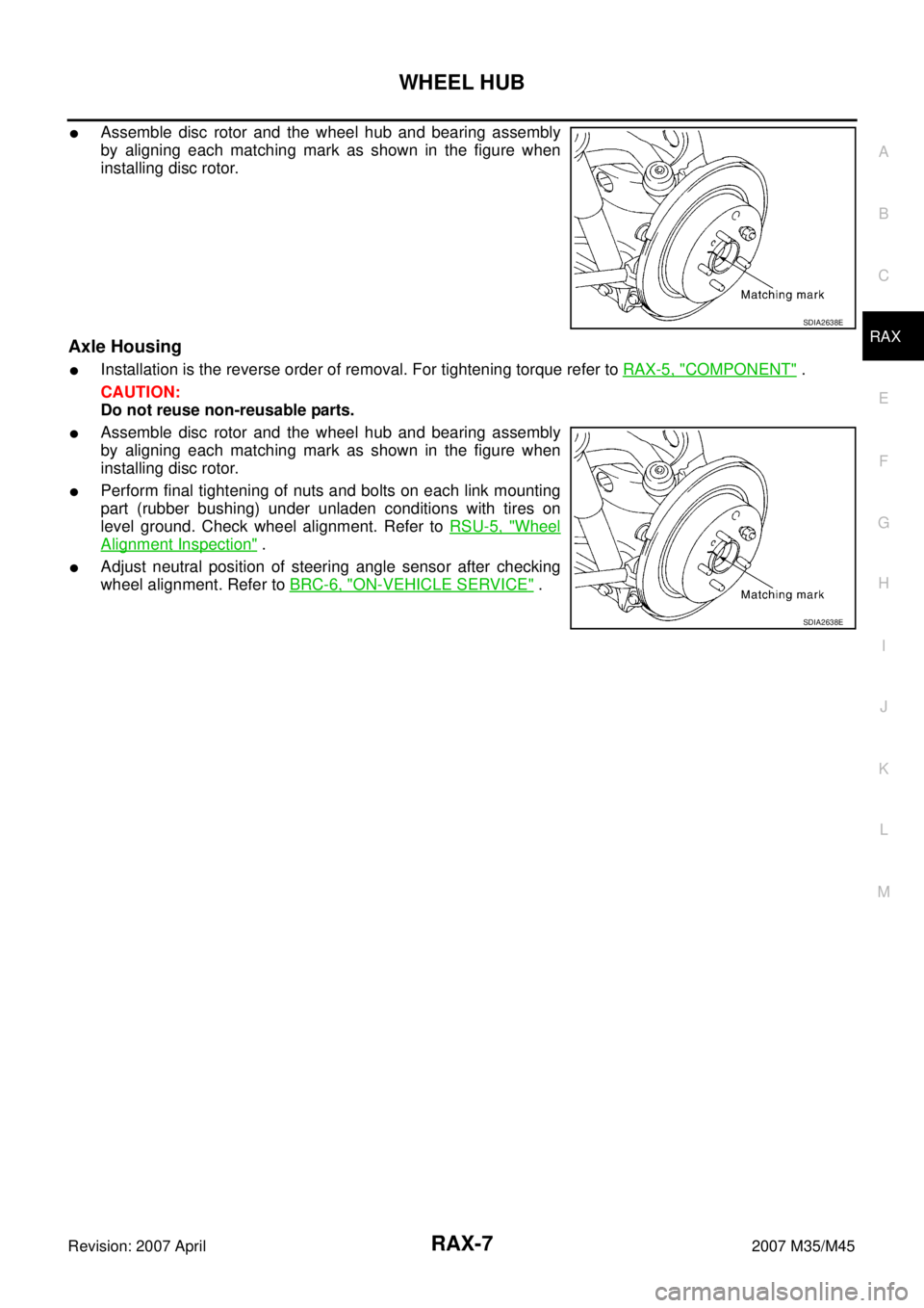
�Assemble disc rotor and the wheel hub and bearing assembly
by aligning each matching mark as shown in the figure when
installing disc rotor.
Axle Housing
�Installation is the reverse order of removal. For tightening torque refer to RAX-5, "COMPONENT" .
CAUTION:
Do not reuse non-reusable parts.
�Assemble disc rotor and the wheel hub and bearing assembly
by aligning each matching mark as shown in the figure when
installing disc rotor.
�Perform final tightening of nuts and bolts on each link mounting
part (rubber bushing) under unladen conditions with tires on
level ground. Check wheel alignment. Refer to RSU-5, "
Wheel
Alignment Inspection" .
�Adjust neutral position of steering angle sensor after checking
wheel alignment. Refer to BRC-6, "
ON-VEHICLE SERVICE" .
SDIA2638E
SDIA2638E