Page 3997 of 4647

PS-16
STEERING COLUMN
Revision: 2007 April2007 M35/M45
INSPECTION AFTER REMOVAL
�Check each part of steering column assembly for damage or other malfunctions. Replace if there are.
�Measure the length L as shown in the figure if vehicle has been
involved in a minor collision. Replace steering column assembly
if outside the standard.
�Measure steering column assembly rotating torque using preload gauge [SST: ST3127S000]. Replace
steering column assembly if outside the standard.
INSTALLATION OF STEERING COLUMN ASSEMBLY
�Installation is the reverse order of removal. For tightening torque, refer to PS-13, "COMPONENTS" .
�When installing upper joint, the angle which upper joint yoke (1)
forms with shaft center groove (A) should be at 90°.
�Adjust neutral position of steering angle sensor. Refer to BRC-6,
"Adjustment of Steering Angle Sensor Neutral Position" .
INSPECTION AFTER INSTALLATION
Make sure that steering wheel operates smoothly by turning several times from full left stop to full right stop.
SGIA1177E
Steering column length LTelescopic maximum 551 – 555 mm (21.69 – 21.85 in)
Telescopic minimum 591 – 595 mm (23.27 – 23.43 in)
Rotating torque : 0 – 0.2 N·m (0 – 0.02 kg-m, 0 – 1 in-lb)
SGIA1290E
Page 3998 of 4647

STEERING COLUMN
PS-17
C
D
E
F
H
I
J
K
L
MA
B
PS
Revision: 2007 April2007 M35/M45
Disassembly and AssemblyNGS000DB
COMPONENTS
DISASSEMBLY
1. Remove fixing screws of telescopic sensor, and then remove telescopic sensor from steering column.
2. Remove fixing screw of bracket, and then remove bracket from telescopic motor.
3. Remove fixing bolt of telescopic motor, and then remove telescopic motor from steering column.
4. Remove fixing screws of tilt sensor, and then remove tilt sensor from steering column.
5. Remove fixing bolt of tilt motor, and then remove tilt motor from steering column.
6. Remove fixing screws of brackets, and then remove brackets from steering column.
INSPECTION AFTER DISASSEMBLY
Check component parts for damage or other malfunctions. Replace if there are.
ASSEMBLY
Assembly is the reverse order of disassembly. For tightening torque, refer to PS-17, "COMPONENTS" .
1. Bracket 2. Bracket 3. Steering column
4. Telescopic motor 5. Bracket 6. Telescopic sensor
7. Tilt sensor 8. Tilt motor 9. Bracket
10. Bracket
Refer to GI-11, "
Components" , for the symbols in the figure.
SGIA1634E
Page 4001 of 4647

PS-20
POWER STEERING GEAR AND LINKAGE
Revision: 2007 April2007 M35/M45
8. Remove steering hydraulic piping bracket from front suspension member. Refer to PS-39, "HYDRAULIC
LINE" .
9. Remove power steering solenoid valve harness connector. Refer to PS-21, "
COMPONENTS" .
10. Remove rack stay (2WD) or front cross bar (AWD). Refer to FSU-8, "
Components" , FSU-26, "Compo-
nents" .
11. Remove mounting bolts and nuts of steering gear assembly, and then remove steering gear assembly
from vehicle.
INSTALLATION
Installation is the reverse order of removal. For tightening torque, refer to PS-19, "COMPONENTS" .
�When installing lower joint to steering gear assembly, follow the procedure listed below.
–Set rack of steering gear in the neutral position.
NOTE:
To get the neutral position of rack, turn gear-sub assembly and measure the distance of inner socket, and
then measure the intermediate position of the distance.
–Align rear cover cap projection (A) with the marking position (B)
of gear housing assembly.
–Install slit part of lower joint (C) aligning with the projection (A) of
rear cover cap (1). Make sure that the slit part of lower joint (C)
is aligned with both the projection (A) of rear cover cap (1) and
the marking position (B) of gear housing assembly.
�After installation, bleed air from the steering hydraulic system.
Refer to PS-8, "
Air Bleeding Hydraulic System" .
�Perform final tightening of nuts and bolts on each part under
unladen conditions with tires on level ground when removing
steering gear assembly. Check wheel alignment. Refer to FSU-
6, "Wheel Alignment Inspection" , FSU-24, "Wheel Alignment
Inspection" .
�Adjust neutral position of steering angle sensor after checking wheel alignment. Refer to BRC-6, "Adjust-
ment of Steering Angle Sensor Neutral Position" .
INSPECTION AFTER INSTALLATION
Make sure that steering wheel operates smoothly by turning several times from full left stop to full right stop.
SGIA1175E
Page 4004 of 4647
POWER STEERING GEAR AND LINKAGE
PS-23
C
D
E
F
H
I
J
K
L
MA
B
PS
Revision: 2007 April2007 M35/M45
14. Push rack oil seal inside with a 29 mm (1.14 in) socket and an
extension bar to push out rack oil seal (inner side) from gear
housing assembly.
CAUTION:
Do not damage gear housing assembly and cylinder inner
wall. Gear housing assembly must be replaced if damaged
because it may cause fluid leakage.
INSPECTION AFTER DISASSEMBLY
Boot
Check boot for cracks, and replace it if a malfunction is detected.
Rack Assembly
Check rack for damage or wear, and replace it if a malfunction is detected.
Gear-Sub Assembly
�Check gear-sub assembly for damage or wear, and replace it if a malfunction is detected.
�Rotate gear-sub assembly and check for torque variation or rattle, and replace it if a malfunction is
detected.
Gear Housing Assembly
Check gear housing assembly for damage and scratches (inner wall). Replace if there are.
SGIA0179E
Page 4005 of 4647

PS-24
POWER STEERING GEAR AND LINKAGE
Revision: 2007 April2007 M35/M45
Outer Socket and Inner Socket
1. Ball joint swinging torque
�Hook a spring balance at the point shown in the figure and
pull the spring balance. Make sure that the spring balance
reads the specified value when ball stud and inner socket
start to move. Replace outer socket and steering gear assem-
bly if they are outside the standard.
2. Ball joint rotating torque
�Make sure that the reading is within the following specified
range using the preload gauge [SST]. Replace outer socket if
the reading is outside the specified value.
3. Ball joint axial end play
�Apply an axial load of 490 N (50 kg, 111 lb) to ball stud using a
dial gauge. Measure amount of stud movement, and then
make sure that the value is within the following specified
range. Replace outer socket and inner socket if the measured
value is outside the standard.
SGIA0896E
Items Outer socket Inner socket
Measuring point of spring balance Stud cotter pin mounting hole Measuring point at *mark shown in the figure
Swinging torque0.3 – 2.9 N·m
(0.03 – 0.29 kg-m, 3 – 25 in-lb)1.0–7.8 N·m
(0.11 – 0.79 kg-m, 9.0 – 69 in-lb)
Spring balance measurement4.81 – 45.7 N
(0.5 – 4.7 kg, 1.1 – 10.4 lb)8.9 – 64 N
(0.9 – 6.5 kg, 2.0 – 14.3 lb)
Outer socket rotating torque 0.3 – 2.9 N·m (0.03 – 0.29 kg-m, 3 – 25 in-lb)
SGIA0941E
Outer socket 0.5 mm (0.020 in) or less
Inner socket 0.2 mm (0.008 in) or less
SGIA0057E
Page 4007 of 4647
 into rack assembly piston (rack Teflon
ring).
c. Push retainer to adjusting screw side by hand, a")
PS-26
POWER STEERING GEAR AND LINKAGE
Revision: 2007 April2007 M35/M45
b. Insert rack oil seal (inner) into rack assembly piston (rack Teflon
ring).
c. Push retainer to adjusting screw side by hand, and move the
rack assembly inside the gear housing assembly so that the
rack oil seal (inner) can be pressed against the gear housing
assembly.
d. Wrap an OHP sheet [approximately 70 mm (2.76 in) × 100 mm
(3.94 in)]. Around the edge to avoid damaging rack oil seal
(outer). Install rack oil seal over sheet. Then, pull oil seal along
with OHP sheet until they pass rack edge, and remove OHP
sheet.
e. Install end cover assembly to rack edge, and move rack oil seal
(outer) until it contacts with gear housing assembly.
5. Tighten end cover assembly to specified torque using a 36 mm
(1.42 in) open head (suitable tool).
CAUTION:
Do not damage rack assembly. Replace it if damaged
because it may cause fluid leakage.
6. Crimp gear housing assembly at one point using a punch as
shown in the figure so as to prevent end cover assembly from
getting loose after tightening end cover assembly.
7. Apply recommended fluid to O-ring, and then install O-ring to
gear housing assembly.
8. Install gear-sub assembly to gear housing assembly.
9. Install power steering solenoid valve to gear-sub assembly.
10. Decide on the neutral position for the rack.
11. Install rear cover cap to gear sub-assembly.
CAUTION:
Make sure that the projection of rear cover cap is aligned
with the marking position of gear housing assembly.
SGIA0671E
SGIA0157E
SST081B
SGIA0871E
Drive type 2WD AWD
Rack stroke L 68.5 mm (2.697 in) 67.0 mm (2.638 in)
SGIA0877E
Page 4008 of 4647
, and then screw in the adju")
POWER STEERING GEAR AND LINKAGE
PS-27
C
D
E
F
H
I
J
K
L
MA
B
PS
Revision: 2007 April2007 M35/M45
12. Apply recommended thread locking sealant to the thread (2
turns thread), and then screw in the adjusting screw until it
reaches height “H” from gear housing assembly measured
before disassembling.
13. Move rack assembly 10 strokes throughout the full stroke so that
the parts can fit with each other.
14. Measure pinion rotating torque within ±180° of neutral position
of the rack assembly using the preload gauge [SST] and preload
adapter [SST]. Stop the gear at the point where highest torque is
read.
15. Loosen adjusting screw and retighten to 5.4 N·m (0.55 kg-m, 48
in-lb), and then loosen by 20 to 40°.
16. Measure pinion rotating torque using the preload adapter [SST]
and preload gauge [SST] to make sure that the measured value
is within the standard. Readjust if the value is outside the stan-
dard. Replace steering gear assembly if the value is outside the
standard after readjusting or adjusting screw rotating torque is 5
N·m (0.51 kg-m, 44 in-lb) or less.
17. Apply recommended liquid gasket to inner socket and turn pinion fully to left with inner socket installed to
gear housing assembly.
18. Set dial gauge as shown in the figure. Measure vertical move-
ment of rack assembly when pinion is turned clockwise with
torque of 19.6 N·m (2.0 kg-m, 14 ft-lb). Readjust adjusting screw
angle if the measured value is outside the standard. Replace
steering gear assembly if the measured value is still outside the
standard or adjusting screw rotating torque is 5 N·m (0.51 kg-m,
44 in-lb) or less.
SGIA0624E
SGIA0942E
SGIA0936E
Pinion rotating torque standard 2WD AWD
Around neutral position (within±100°)
Average A1.95 - 2.58 N·m
(0.20 - 0.26 kg-m, 18 - 22 in-lb)2.27 - 3.05 N·m
(0.24 - 0.31 kg-m, 20 - 26 in-lb)
Maximum variation B 0.98 N·m (0.10 kg-m, 9.0 in-lb)
SGIA1185E
Page 4010 of 4647
POWER STEERING GEAR AND LINKAGE
PS-29
C
D
E
F
H
I
J
K
L
MA
B
PS
Revision: 2007 April2007 M35/M45
�Bent cut end of the wire toward rack axial as shown in the fig-
ure after twisting the wire 4 to 4.5 turns so that cut end does
not contact with boot.
CAUTION:
Keep gap from cylinder tube 5 mm (0.20 in) or more.
23. Install cylinder tubes to gear housing assembly.
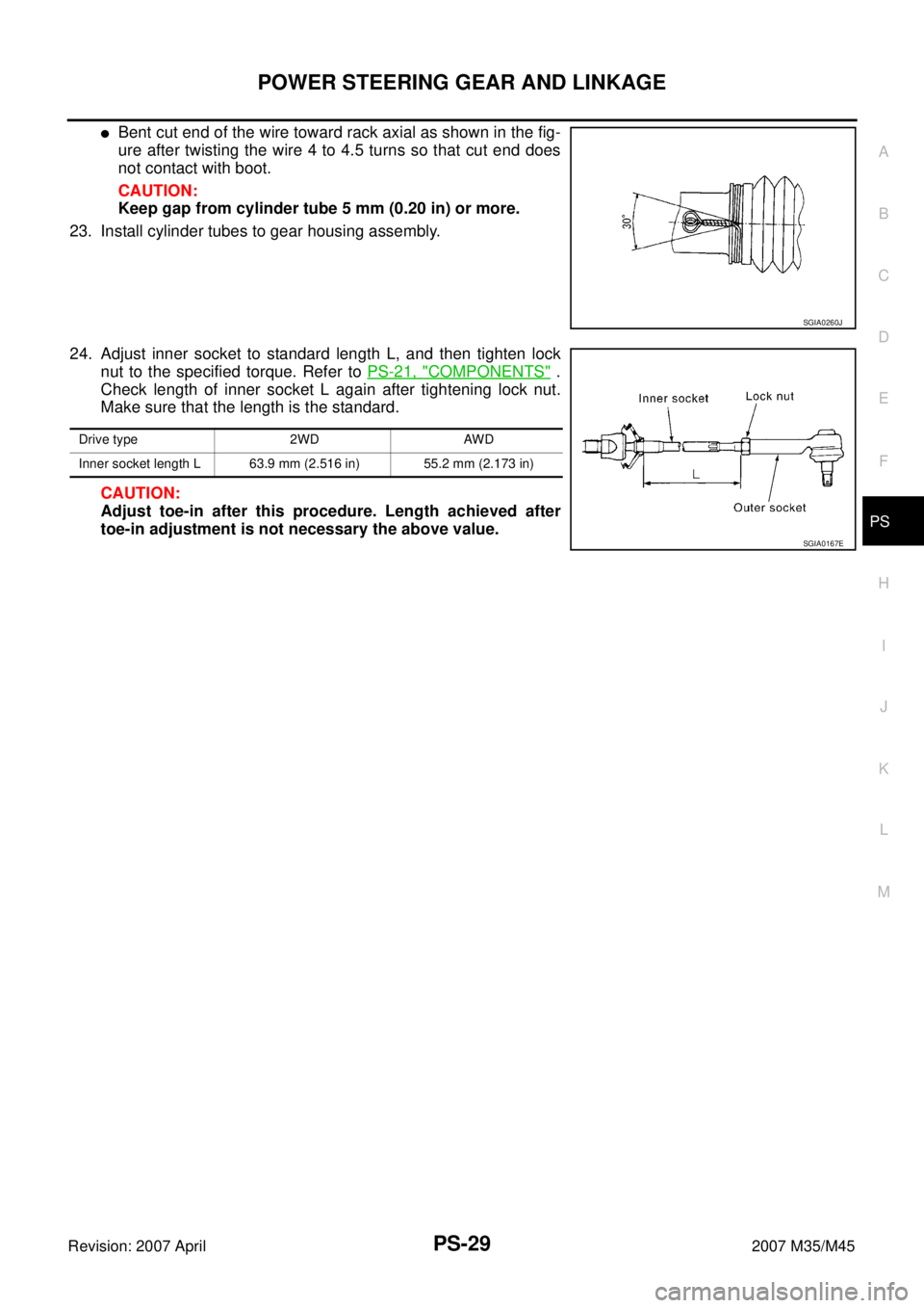
24. Adjust inner socket to standard length L, and then tighten lock
nut to the specified torque. Refer to PS-21, "
COMPONENTS" .
Check length of inner socket L again after tightening lock nut.
Make sure that the length is the standard.
CAUTION:
Adjust toe-in after this procedure. Length achieved after
toe-in adjustment is not necessary the above value.
SGIA0260J
Drive type 2WD AWD
Inner socket length L 63.9 mm (2.516 in) 55.2 mm (2.173 in)
SGIA0167E
 socket and an
extension bar to push out rack oil s")