Page 1210 of 4647

BL-277
C
D
E
F
G
H
J
K
L
MA
B
BL
Revision: 2007 April2007 M35/M45
DTC P1611 ID DISCORD, IMM-ECMNIS0020T
Self-diagnostic results:
“ID DISCORD, IMM-ECM�")
IVIS (INFINITI VEHICLE IMMOBILIZER SYSTEM-NATS)
BL-277
C
D
E
F
G
H
J
K
L
MA
B
BL
Revision: 2007 April2007 M35/M45
DTC P1611 ID DISCORD, IMM-ECMNIS0020T
Self-diagnostic results:
“ID DISCORD, IMM-ECM” displayed on CONSULT-II screen
1. CONFIRM SELF-DIAGNOSTIC RESULTS
Confirm SELF-DIAGNOSTIC RESULTS “ID DISCORD, IMM-ECM” displayed on CONSULT-II screen.
NOTE:
“ID DISCORD IMM-ECM”:
Registered ID of BCM is in discord with that of ECM.
Is CONSULT-II screen displayed as shown in figure?
Ye s > > G O T O 2 .
No >> GO TO BL-268, "
“NATS V5.0” SELF-DIAGNOSTIC
RESULTS ITEM CHART" .
2. PERFORM INITIALIZATION WITH CONSULT-II
Perform initialization with CONSULT-II. Re-register all NATS ignition key IDs.
For initialization, refer to “CONSULT-II Operation Manual NATS-
IVIS/NVIS”.
NOTE:
If the initialization is not completed or malfunctions, CONSULT-II
shows message on the screen.
Can the system be initialized?
Ye s > >�Start engine. (END)
�(System initialization had not been completed.)
No >> ECM is malfunctioning.
�Replace ECM.
�Perform initialization with CONSULT-II
For initialization, refer to “CONSULT-II Operation Manual NATS-IVIS/NVIS”
Removal and Installation of Key SlotNIS0020U
REMOVAL
1. Remove instrument driver lower panel. Refer to IP-10, "INSTRUMENT PANEL ASSEMBLY" .
2. Disconnect key slot connector.
3. Remove key slot mounting screw, and then remove key slot.
INSTALLATION
Installation is in the reverse order of removal.
PIIA1262E
SEL297W
PIIB6284E
Page 1218 of 4647

3. Side body assembly (RH&LH)
4. Outer front pillar reinforcement (RH&LH)
5. Center pillar")
BODY REPAIR
BL-285
C
D
E
F
G
H
J
K
L
MA
B
BL
Revision: 2007 April2007 M35/M45
1. Hood
2. Front fender (RH&LH)
3. Side body assembly (RH&LH)
4. Outer front pillar reinforcement (RH&LH)
5. Center pillar reinforcement (RH&LH)
6. Outer roof side rail reinforcement (RH&LH)
7. Outer sill reinforcement (RH&LH)
8. Inner roof side rail (RH&LH)
9. Inner center pillar (RH&LH)
10. Front roof rail brace (RH&LH)
11. Outer sill (RH&LH)
12. Inner rear pillar assembly (RH&LH)
13. Inner rear pillar rear (RH&LH)
14. Inner rear pillar reinforcement (RH&LH)
15. Outer rear wheelhouse (RH&LH)
16. Outer rear wheelhouse extension (RH&LH)
17. Inner rear wheelhouse (RH&LH)
18. Side parcel shelf assembly (RH&LH)
19. Seat back support (RH&LH)
20. Parcel shelf assembly
21. Rear waist
22. Roof assembly
23. Front roof rail
24. Front roof bow
25. Rear roof bow
26. Rear roof rail
27. Rear fender assembly (RH&LH)
28. Rear fender extension (RH&LH)
29. Rear bumper side bracket
30. Fuel filler lid (RH)
31. Rear panel assembly
32. Upper rear bumper retainer
33. Lower rear bumper retainer
34. Front door assembly (RH&LH)
35. Outer front door panel (RH&LH)
36. Rear door assembly (RH&LH)
37. Outer rear door panel (RH&LH)
38. Trunk lid
39. Front bumper reinforcement
40. Rear bumper stay
41. Rear bumper reinforcement
Page 1219 of 4647

BL-286
BODY REPAIR
Revision: 2007 April2007 M35/M45
Corrosion ProtectionNIS0020Z
DESCRIPTION
To provide improved corrosion prevention, the following anti-corrosive measures have been implemented in
NISSAN production plants. When repairing or replacing body panels, it is necessary to use the same anti-cor-
rosive measures.
Anti-corrosive Precoated Steel (Galvannealed Steel)
To improve repairability and corrosion resistance, a new type of anti-
corrosive precoated steel sheet has been adopted replacing conven-
tional zinc-coated steel sheet.
Galvannealed steel is electroplated and heated to form Zinc-iron
alloy, which provides excellent and long term corrosion resistance
with cationic electrodeposition primer.
Nissan Genuine Service Parts are fabricated from galvannealed steel. Therefore, it is recommended that
GENUINE NISSAN PARTS or equivalent be used for panel replacement to maintain the anti-corrosive perfor-
mance built into the vehicle at the factory.
Phosphate Coating Treatment and Cationic Electrodeposition Primer
A phosphate coating treatment and a cationic electrodeposition primer, which provide excellent corrosion pro-
tection, are employed on all body components.
CAUTION:
Confine paint removal during welding operations to an absolute
minimum.
Nissan Genuine Service Parts are also treated in the same manner. Therefore, it is recommended that GENU-
INE NISSAN PARTS or equivalent be used for panel replacement to maintain anti-corrosive performance built
into the vehicle at the factory.
SIIA2294E
PIIA0095E
Page 1220 of 4647
BODY REPAIR
BL-287
C
D
E
F
G
H
J
K
L
MA
B
BL
Revision: 2007 April2007 M35/M45
UNDERCOATING
The underside of the floor and wheelhouse are undercoated to prevent rust, vibration, noise and stone chip-
ping. Therefore, when such a panel is replaced or repaired, apply undercoating to that part. Use an undercoat-
ing which is rust preventive, soundproof, vibration-proof, shock-resistant, adhesive, and durable.
Precautions in Undercoating
1. Do not apply undercoating to any place unless specified (such as the areas above the muffler and three
way catalyst which are subjected to heat).
2. Do not undercoat the exhaust pipe or other parts which become hot.
3. Do not undercoat rotating parts.
4. Apply bitumen wax after applying undercoating.
5. After putting seal on the vehicle, put undercoating on it.
SIIA2735E
Page 1226 of 4647
BODY REPAIR
BL-293
C
D
E
F
G
H
J
K
L
MA
B
BL
Revision: 2007 April2007 M35/M45
PANEL PARTS MATCHING MARKS
A mark has been placed on each body panel to indicate the parts matching positions. When repairing parts
damaged by an accident which might affect the vehicle structure (members, pillars, etc.), more accurate and
effective repair will be possible by using these marks together with body alignment specifications.
SIIA2460E
Page 1239 of 4647
BL-306
BODY REPAIR
Revision: 2007 April2007 M35/M45
Precautions in Repairing High Strength SteelNIS00214
High strength steel is used for body panels in order to reduce vehicle weight.
Accordingly, precautions in repairing automotive bodies made of high strength steel are described below:
HIGH STRENGTH STEEL (HSS) USED IN NISSAN VEHICLES
SP130 is the most commonly used HSS.
SP150 HSS is used only on parts that require much more strength.Tensile strength Nissan/Infiniti designation Major applicable parts
373 N/mm
2
(38kg/mm2 ,54klb/sq in)SP130
�Front & rear side member assembly
�Front side member closing plate assembly
�Front strut housing
�Lower dash
�Rear seat crossmember
�Other reinforcements
785-1350 N/mm
2
(80-138kg/mm2 , 114-196klb/sq in)SP150
�Center pillar reinforcement
(Component part)
�Outer roof side rail reinforcement
(Component part)
Page 1240 of 4647

BODY REPAIR
BL-307
C
D
E
F
G
H
J
K
L
MA
B
BL
Revision: 2007 April2007 M35/M45
Read the Following Precautions When Repairing HSS:
1. Additional points to consider
�The repair of reinforcements (such as side members) by heat-
ing is not recommended since it may weaken the component.
When heating is unavoidable, do not heat HSS parts above
550°C (1,022°F).
Verify heating temperature with a thermometer.
(Crayon-type and other similar type thermometer are appro-
priate.)
�When straightening body panels, use caution in pulling any
HSS panel. Because HSS is very strong, pulling may cause
deformation in adjacent portions of the body. In this case,
increase the number of measuring points, and carefully pull
the HSS panel.
�When cutting HSS panels, avoid gas (torch) cutting if possi-
ble. Instead, use a saw to avoid weakening surrounding areas
due to heat. If gas (torch) cutting is unavoidable, allow a mini-
mum margin of 50 mm (1.97in).
�When welding HSS panels, use spot welding whenever possi-
ble in order to minimize weakening surrounding areas due to
heat.
If spot welding is impossible, use M.I.G. welding. Do not use
gas (torch) welding because it is inferior in welding strength.
PIIA0115E
PIIA0116E
PIIA0117E
PIIA0144E
Page 1241 of 4647
BL-308
BODY REPAIR
Revision: 2007 April2007 M35/M45
�The spot weld on HSS panels is harder than that of an ordi-
nary steel panel.
Therefore, when cutting spot welds on a HSS panel, use a
low speed high torque drill (1,000 to 1,200 rpm) to increase
drill bit durability and facilitate the operation.
2. Precautions in spot welding HSS
This work should be performed under standard working condi-
tions. Always note the following when spot welding HSS:
�The electrode tip diameter must be sized properly according
to the metal thickness.
�The panel surfaces must fit flush to each other, leaving no
gaps.
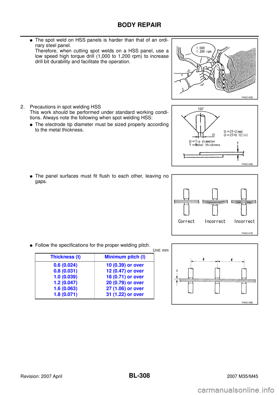
�Follow the specifications for the proper welding pitch.
Unit: mm
PIIA0145E
PIIA0146E
PIIA0147E
Thickness (t) Minimum pitch (l)
0.6 (0.024)
0.8 (0.031)
1.0 (0.039)
1.2 (0.047)
1.6 (0.063)
1.8 (0.071)10 (0.39) or over
12 (0.47) or over
18 (0.71) or over
20 (0.79) or over
27 (1.06) or over
31 (1.22) or over
PIIA0148E