Page 1242 of 4647

BODY REPAIR
BL-309
C
D
E
F
G
H
J
K
L
MA
B
BL
Revision: 2007 April2007 M35/M45
Rear fender hemming process
1. A wheel arch is to be installed and hemmed over left and right outer wheel house.
2. In order to hem the wheel arch, it is necessary to repair any damaged or defaced parts around outer
wheel house.
CAUTION:
Ensure that the area that is to be glued around outer wheelhouse is undamaged or defaced.
Procedure of the hemming process
�Peel off old bonding material on the surface of outer wheelhouse
and clean thoroughly.
�Peel off a primer coat in the specified area where new adhesive
is to be applied on rear fender (the replacing part).
�Apply new adhesive to both specified areas of outer wheelhouse
and rear fender.
�Attach rear fender to the body of the car, and weld the required
part except the hemming part.
�Bend the welded part starting from the center of the wheel arch
gradually with a hammer and a dolly. (Also hem the end of the
flange.)
�Hemming with a hammer is conducted to an approximate angle
of 80 degrees.
�Starting from the center, hem the wheel arch gradually, using
slight back and forth motion with a hemming tool.
�Seal up the area around the hemmed end of the flange. 3M automix panel bond 8115,
or any equivalents
SIIA2244E
SIIA2245E
SIIA2246E
SIIA2247E
Page 1243 of 4647

BL-310
BODY REPAIR
Revision: 2007 April2007 M35/M45
Foam RepairNIS0028Z
During factory body assembly, foam insulators are installed in certain body panels and locations around the
vehicle. Use the following procedure(s) to replace any factory-installed foam insulators.
URETHANE FOAM APPLICATIONS
Use commercially available spray foam for sealant (foam material) repair of material used on vehicle. Read
instructions on product for fill procedures.
1. Fill procedures after installation of service part.
–Remove foam material remaining on vehicle side.
–Clean area in which foam was removed.
–Install service part.
–Insert nozzle into hole near fill area and fill foam material or fill in enough to close gap with the service
part.
2. Fill procedures before installation of service part.
–Remove foam material remaining on vehicle side.
–Clean area in which foam was removed.
–Fill foam material on wheelhouse outer side.
NOTE:
Fill in enough to close gap with service part while avoiding
flange area.
–Install service part.
NOTE:
Refer to label for information on working times.
LIIA1081E
LIIA1082E
Page 1263 of 4647
BL-330
BODY REPAIR
Revision: 2007 April2007 M35/M45
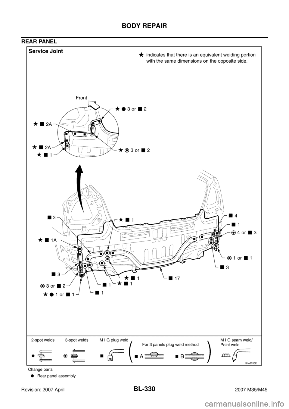
REAR PANEL
Change parts
�Rear panel assembly
SIIA2705E
Page 1264 of 4647
BODY REPAIR
BL-331
C
D
E
F
G
H
J
K
L
MA
B
BL
Revision: 2007 April2007 M35/M45
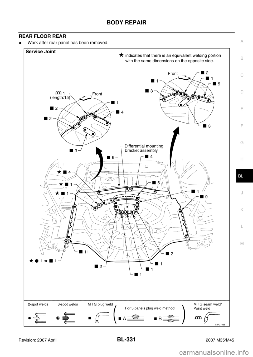
REAR FLOOR REAR
�Work after rear panel has been removed.
SIIA2706E
Page 1266 of 4647
BODY REPAIR
BL-333
C
D
E
F
G
H
J
K
L
MA
B
BL
Revision: 2007 April2007 M35/M45
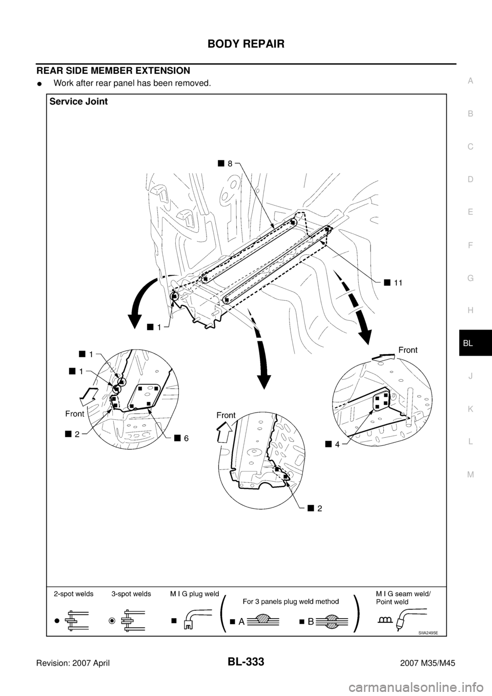
REAR SIDE MEMBER EXTENSION
�Work after rear panel has been removed.
SIIA2495E
Page 1270 of 4647
 “AIR BAG” and “SEAT
BELT PRE-TENSIONER”
NF")
PRECAUTIONS
BR-3
C
D
E
G
H
I
J
K
L
MA
B
BR
Revision: 2007 April2007 M35/M45
PRECAUTIONSPFP:00001
Precautions for Supplemental Restraint System (SRS) “AIR BAG” and “SEAT
BELT PRE-TENSIONER”
NFS000RO
The Supplemental Restraint System such as “AIR BAG” and “SEAT BELT PRE-TENSIONER”, used along
with a front seat belt, helps to reduce the risk or severity of injury to the driver and front passenger for certain
types of collision. This system includes seat belt switch inputs and dual stage front air bag modules. The SRS
system uses the seat belt switches to determine the front air bag deployment, and may only deploy one front
air bag, depending on the severity of a collision and whether the front occupants are belted or unbelted.
Information necessary to service the system safely is included in the SRS and SB section of this Service Man-
ual.
WARNING:
�To avoid rendering the SRS inoperative, which could increase the risk of personal injury or death
in the event of a collision which would result in air bag inflation, all maintenance must be per-
formed by an authorized NISSAN/INFINITI dealer.
�Improper maintenance, including incorrect removal and installation of the SRS, can lead to per-
sonal injury caused by unintentional activation of the system. For removal of Spiral Cable and Air
Bag Module, see the SRS section.
�Do not use electrical test equipment on any circuit related to the SRS unless instructed to in this
Service Manual. SRS wiring harnesses can be identified by yellow and/or orange harnesses or
harness connectors.
Precautions for Procedures without Cowl Top CoverNFS000RP
When performing the procedure after removing cowl top cover, cover
the lower end of windshield with urethane, etc.
Precautions for Brake SystemNFS000RQ
�Clean dust on front brake and rear brake with a vacuum dust collector. Do not blow with compressed air.
�Recommended fluid is brake fluid “DOT 3”. Refer to MA-12, "Fluids and Lubricants" .
�Never reuse drained brake fluid.
�Be careful not to splash brake fluid on painted areas; it may cause paint damage. If brake fluid is splashed
on painted areas, wash it away with water immediately.
�Use clean brake fluid, to clean or wash all parts of master cylinder and disc brake caliper, etc.
�Never use mineral oils such as gasoline or kerosene. They will ruin rubber parts of the hydraulic system.
�Use flare nut torque wrench when installing brake tube.
�When installing brake tube and hose, be sure to check torque.
�Before working, turn ignition switch OFF and disconnect con-
nectors of ABS actuator and electric unit (control unit) or battery
cable from the negative terminal.
�Burnish the brake contact surfaces after refinishing or replacing
rotors, after replacing pads, or if a soft pedal occurs at very low
mileage. Refer to BR-27, "
BRAKE BURNISHING PROCE-
DURE" (front disc brake), BR-33, "BRAKE BURNISHING PRO-
CEDURE" (rear disc brake).
WARNING:
�Clean brake pads and shoes with a waste cloth, then wipe with a dust collector.
PIIB3706J
SBR686C
Page 1273 of 4647

BR-6
BRAKE PEDAL
Revision: 2007 April2007 M35/M45
BRAKE PEDALPFP:46501
Inspection and AdjustmentNFS000RT
Play and clearance inspection between brake pedal and floor panel with pedal depressed.
�Check brake pedal play.
�Check brake pedal height from dash lower panel (1).
�Adjust height referring to the following specifications.
ADJUSTMENT
1. Loosen stop lamp switch and brake switch by turning it counter-
clockwise by 45°.
2. Loosen lock nut (A) on the input rod to rotate input rod for adjust-
ing brake pedal height to the specified one, and tighten lock nut
(A). Refer to BR-18, "
COMPONENTS" .
CAUTION:
Make sure the threaded end of input rod stays inside clevis.
3. With the pedal pulled and held by hand, press stop lamp switch
and brake switch until its threaded end contacts stopper.
4. With the threaded end of the stop lamp switch and brake switch
contacting the bracket, rotate the switch clockwise by 45° to
secure.
CAUTION:
Make sure that the clearance “C” between bracket and end
of stop lamp switch and brake switch is within the standard.
5. Check pedal play.
CAUTION:
Make sure that stop lamps goes off when pedal is released.
6. Start engine to check brake pedal depression height when
depressed. Refer to BR-6, "
Inspection and Adjustment" .
H1Brake pedal height
[from dash lower panel (1) top surface]157 − 167 mm (6.18 −
6.57 in)
H
2
Depressed brake pedal height
[under a force of 490 N (50 kg, 110 lb) with
engine running]90 mm (3.54 in) or more
CClearance between threaded end of the stop
lamp switch/brake switch (2) and bracket (3)0.74 − 1.96 mm (0.0291 −
0.0772 in)
A Pedal play3 − 11 mm (0.12 − 0.43
in)
SFIA2743J
PFIA0824E
Page 1275 of 4647

BR-8
BRAKE PEDAL
Revision: 2007 April2007 M35/M45
REMOVAL
1. Remove instrument driver lower panel. Refer to IP-10, "INSTRUMENT PANEL ASSEMBLY" .
2. Remove steering column assembly. Refer to PS-13, "
STEERING COLUMN" .
3. Disconnect stop lamp switch and brake switch connector.
4. Remove stop lamp switch and brake switch from brake pedal assembly.
5. Disconnect brake pedal stroke sensor connector.(With pre-crash seat belt)
CAUTION:
Brake pedal stroke sensor is not detachable. Do not detach it.
6. Remove snap pin and clevis pin from clevis of brake booster.
7. Remove brake pedal assembly mounting nuts. Pull brake booster toward engine room to the extent that
does not deform brake tube.
8. Remove brake booster clevis from input rod.
9. Remove mounting bolt and then remove brake pedal assembly from vehicle.
INSPECTION AFTER REMOVAL
�Check the items below. If any is found, replace brake pedal
assembly.
–Check brake pedal upper rivet for deformation.
–Make sure that joint length “L” of sub-bracket and sliding plate is
4 mm (0.16 in) or more.
–Check brake pedal for bend, damage, and cracks on the welded
parts.
�Check clevis pin and plastic stopper for damage and deforma-
tion. If any is found, replace clevis pin.
INSTALLATION
Installation is the reverse order of removal. Tightening torques for brake pedal assembly mounting nuts and
bolt are referred to BR-7, "
COMPONENTS" . Tightening torque for lock nut is referred to BR-18, "COMPO-
NENTS" .
�Adjust brake pedal height after installing brake pedal assembly to vehicle. Refer to BR-6, "Inspection and
Adjustment" .
SFIA2487E
SBR997