Page 1090 of 4647
INTELLIGENT KEY SYSTEM/ENGINE START FUNCTION
BL-157
C
D
E
F
G
H
J
K
L
MA
B
BL
Revision: 2007 April2007 M35/M45
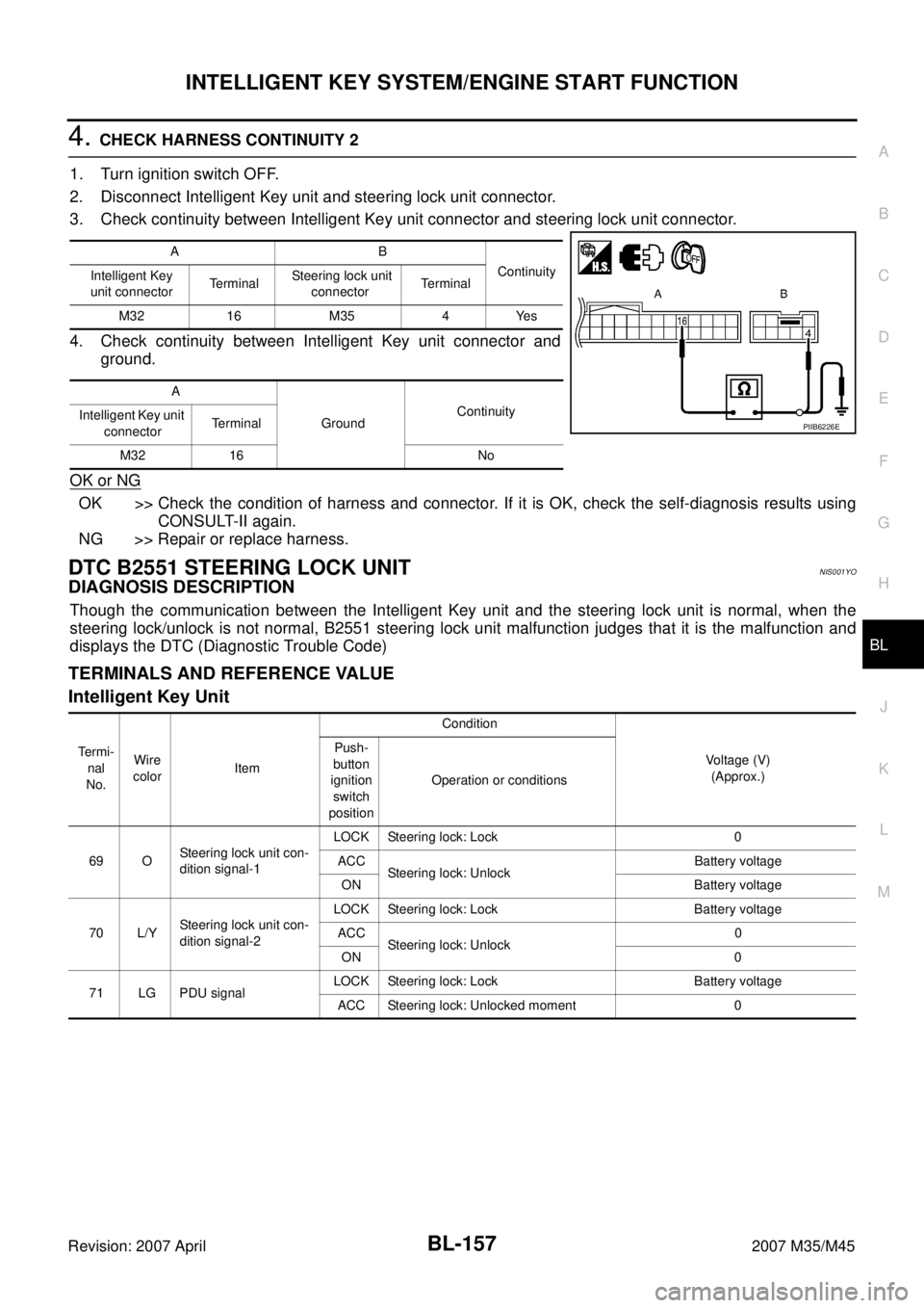
4. CHECK HARNESS CONTINUITY 2
1. Turn ignition switch OFF.
2. Disconnect Intelligent Key unit and steering lock unit connector.
3. Check continuity between Intelligent Key unit connector and steering lock unit connector.
4. Check continuity between Intelligent Key unit connector and
ground.
OK or NG
OK >> Check the condition of harness and connector. If it is OK, check the self-diagnosis results using
CONSULT-II again.
NG >> Repair or replace harness.
DTC B2551 STEERING LOCK UNITNIS001YO
DIAGNOSIS DESCRIPTION
Though the communication between the Intelligent Key unit and the steering lock unit is normal, when the
steering lock/unlock is not normal, B2551 steering lock unit malfunction judges that it is the malfunction and
displays the DTC (Diagnostic Trouble Code)
TERMINALS AND REFERENCE VALUE
Intelligent Key Unit
AB
Continuity
Intelligent Key
unit connectorTerminal Steering lock unit
connectorTerminal
M32 16 M35 4 Yes
A
GroundContinuity
Intelligent Key unit
connectorTerminal
M32 16 No
PIIB6226E
Te r m i -
nal
No.Wire
colorItemCondition
Voltage (V)
(Approx.) Push-
button
ignition
switch
positionOperation or conditions
69 OSteering lock unit con-
dition signal-1LOCK Steering lock: Lock 0
ACC
Steering lock: UnlockBattery voltage
ON Battery voltage
70 L/YSteering lock unit con-
dition signal-2LOCK Steering lock: Lock Battery voltage
ACC
Steering lock: Unlock0
ON 0
71 LG PDU signalLOCK Steering lock: Lock Battery voltage
ACC Steering lock: Unlocked moment 0
Page 1092 of 4647
INTELLIGENT KEY SYSTEM/ENGINE START FUNCTION
BL-159
C
D
E
F
G
H
J
K
L
MA
B
BL
Revision: 2007 April2007 M35/M45
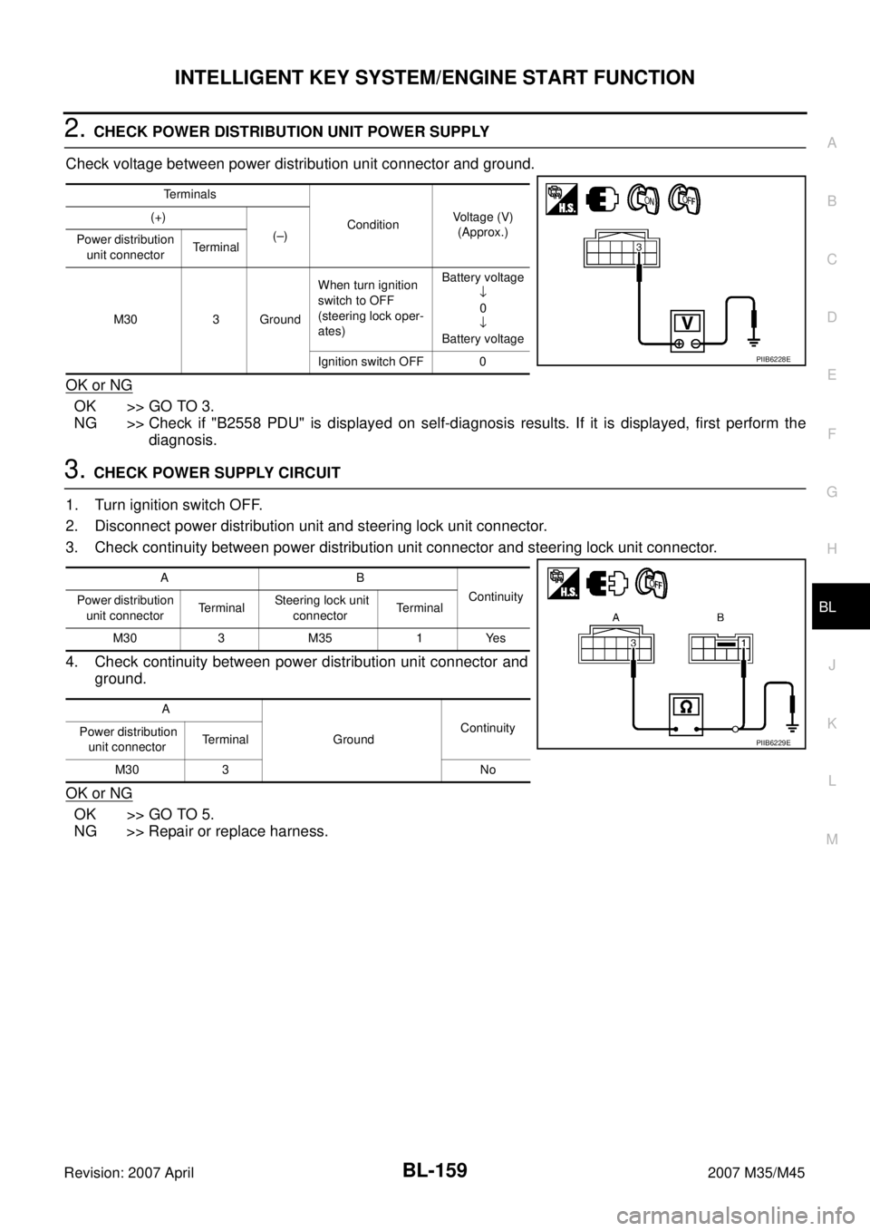
2. CHECK POWER DISTRIBUTION UNIT POWER SUPPLY
Check voltage between power distribution unit connector and ground.
OK or NG
OK >> GO TO 3.
NG >> Check if "B2558 PDU" is displayed on self-diagnosis results. If it is displayed, first perform the
diagnosis.
3. CHECK POWER SUPPLY CIRCUIT
1. Turn ignition switch OFF.
2. Disconnect power distribution unit and steering lock unit connector.
3. Check continuity between power distribution unit connector and steering lock unit connector.
4. Check continuity between power distribution unit connector and
ground.
OK or NG
OK >> GO TO 5.
NG >> Repair or replace harness.
Terminals
ConditionVoltage (V)
(Approx.) (+)
(–)
Power distribution
unit connectorTerminal
M30 3 GroundWhen turn ignition
switch to OFF
(steering lock oper-
ates)Battery voltage
↓
0
↓
Battery voltage
Ignition switch OFF 0
PIIB6228E
AB
Continuity
Power distribution
unit connectorTerminal Steering lock unit
connectorTerminal
M30 3 M35 1 Yes
A
GroundContinuity
Power distribution
unit connectorTerminal
M30 3 No
PIIB6229E
Page 1093 of 4647
BL-160
INTELLIGENT KEY SYSTEM/ENGINE START FUNCTION
Revision: 2007 April2007 M35/M45
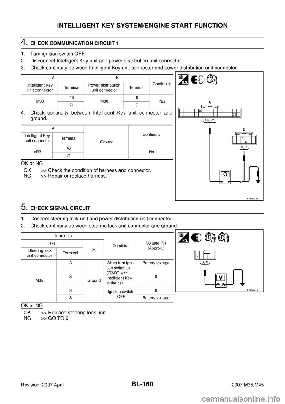
4. CHECK COMMUNICATION CIRCUIT 1
1. Turn ignition switch OFF.
2. Disconnect Intelligent Key unit and power distribution unit connector.
3. Check continuity between Intelligent Key unit connector and power distribution unit connector.
4. Check continuity between Intelligent Key unit connector and
ground.
OK or NG
OK >> Check the condition of harness and connector.
NG >> Repair or replace harness.
5. CHECK SIGNAL CIRCUIT
1. Connect steering lock unit and power distribution unit connector.
2. Check continuity between steering lock unit connector and ground.
OK or NG
OK >> Replace steering lock unit.
NG >> GO TO 6.
AB
Continuity
Intelligent Key
unit connectorTe r m i n a lPower distribution
unit connectorTerminal
M3346
M306
Ye s
71 7
A
GroundContinuity
Intelligent Key
unit connectorTerminal
M3346
No
71
PIIB6230E
Terminals
ConditionVoltage (V)
(Approx.) (+)
(–)
Steering lock
unit connectorTerminal
M353
GroundWhen turn igni-
tion switch to
START with
Intelligent Key
in the carBattery voltage
80
3
Ignition switch:
OFF0
8Battery voltage
PIIB6231E
Page 1094 of 4647
INTELLIGENT KEY SYSTEM/ENGINE START FUNCTION
BL-161
C
D
E
F
G
H
J
K
L
MA
B
BL
Revision: 2007 April2007 M35/M45
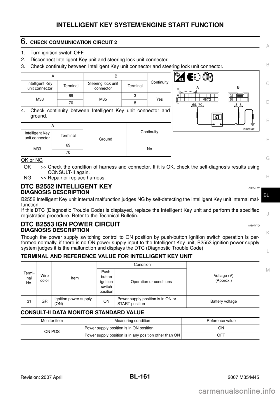
6. CHECK COMMUNICATION CIRCUIT 2
1. Turn ignition switch OFF.
2. Disconnect Intelligent Key unit and steering lock unit connector.
3. Check continuity between Intelligent Key unit connector and steering lock unit connector.
4. Check continuity between Intelligent Key unit connector and
ground.
OK or NG
OK >> Check the condition of harness and connector. If it is OK, check the self-diagnosis results using
CONSULT-II again.
NG >> Repair or replace harness.
DTC B2552 INTELLIGENT KEYNIS001YP
DIAGNOSIS DESCRIPTION
B2552 Intelligent Key unit internal malfunction judges NG by self-detecting the Intelligent Key unit internal mal-
function.
If this DTC (Diagnostic Trouble Code) is displayed, replace the Intelligent Key unit and perform the specified
registration procedure. Refer to the Technical Bulletin.
DTC B2553 IGN POWER CIRCUITNIS001YQ
DIAGNOSIS DESCRIPTION
Though the power supply switching control to ON position by push-button ignition switch operation is per-
formed normally, if there is no ON power supply input to the Intelligent Key unit, B2553 ignition power supply
system judges it is the malfunction and displays the DTC (Diagnostic Trouble Code)
TERMINAL AND REFERENCE VALUE FOR INTELLIGENT KEY UNIT
CONSULT-II DATA MONITOR STANDARD VALUE
AB
Continuity
Intelligent Key
unit connectorTerminalSteering lock unit
connectorTerminal
M3369
M353
Ye s
70 8
A
GroundContinuity
Intelligent Key
unit connectorTerminal
M3369
No
70
PIIB8994E
Te r m i -
nal
No.Wire
colorItemCondition
Voltage (V)
(Approx.) Push-
button
ignition
switch
positionOperation or conditions
31 GRIgnition power supply
(ON)ONPower supply position is in ON or
START positionBattery voltage
Monitor item Measuring condition Reference value
ON POSPower supply position is in ON position ON
Power supply position is in any position other than ON OFF
Page 1097 of 4647
BL-164
INTELLIGENT KEY SYSTEM/ENGINE START FUNCTION
Revision: 2007 April2007 M35/M45
DIAGNOSTIC PROCEDURE
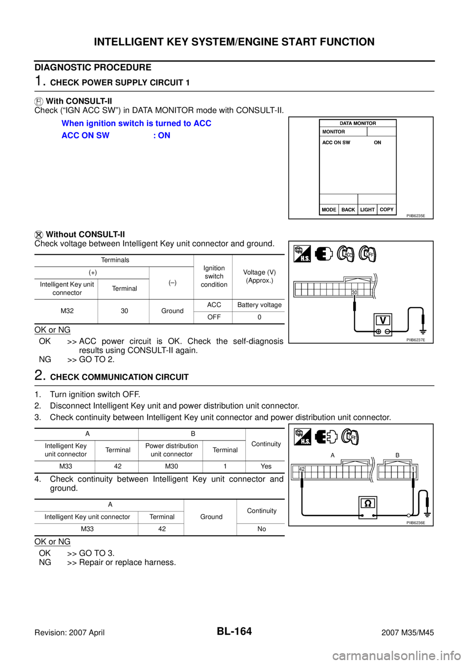
1. CHECK POWER SUPPLY CIRCUIT 1
With CONSULT-II
Check (“IGN ACC SW”) in DATA MONITOR mode with CONSULT-II.
Without CONSULT-II
Check voltage between Intelligent Key unit connector and ground.
OK or NG
OK >> ACC power circuit is OK. Check the self-diagnosis
results using CONSULT-II again.
NG >> GO TO 2.
2. CHECK COMMUNICATION CIRCUIT
1. Turn ignition switch OFF.
2. Disconnect Intelligent Key unit and power distribution unit connector.
3. Check continuity between Intelligent Key unit connector and power distribution unit connector.
4. Check continuity between Intelligent Key unit connector and
ground.
OK or NG
OK >> GO TO 3.
NG >> Repair or replace harness.When ignition switch is turned to ACC
ACC ON SW : ON
PIIB6235E
Terminals
Ignition
switch
conditionVoltage (V)
(Approx.) (+)
(–)
Intelligent Key unit
connectorTerminal
M32 30 GroundACC Battery voltage
OFF 0
PIIB6237E
AB
Continuity
Intelligent Key
unit connectorTe r m i n a lPower distribution
unit connectorTerminal
M33 42 M30 1 Yes
A
GroundContinuity
Intelligent Key unit connector Terminal
M33 42 No
PIIB6236E
Page 1100 of 4647
INTELLIGENT KEY SYSTEM/ENGINE START FUNCTION
BL-167
C
D
E
F
G
H
J
K
L
MA
B
BL
Revision: 2007 April2007 M35/M45
DIAGNOSTIC PROCEDURE
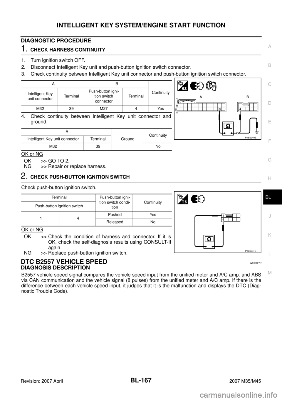
1. CHECK HARNESS CONTINUITY
1. Turn ignition switch OFF.
2. Disconnect Intelligent Key unit and push-button ignition switch connector.
3. Check continuity between Intelligent Key unit connector and push-button ignition switch connector.
4. Check continuity between Intelligent Key unit connector and
ground.
OK or NG
OK >> GO TO 2.
NG >> Repair or replace harness.
2. CHECK PUSH-BUTTON IGNITION SWITCH
Check push-button ignition switch.
OK or NG
OK >> Check the condition of harness and connector. If it is
OK, check the self-diagnosis results using CONSULT-II
again.
NG >> Replace push-button ignition switch.
DTC B2557 VEHICLE SPEEDNIS001YU
DIAGNOSIS DESCRIPTION
B2557 vehicle speed signal compares the vehicle speed input from the unified meter and A/C amp. and ABS
via CAN communication and the vehicle signal (8 pulses) from the unified meter and A/C amp. If there is the
difference between each vehicle speed input, it judges that it is the malfunction and displays the DTC (Diag-
nostic Trouble Code).
AB
Continuity
Intelligent Key
unit connectorTerminalPush-button igni-
tion switch
connectorTerminal
M32 39 M27 4 Yes
A
GroundContinuity
Intelligent Key unit connector Terminal
M32 39 No
PIIB6240E
Terminal Push-button igni-
tion switch condi-
tionContinuity
Push-button ignition switch
14Pushed Yes
Released No
PIIB6241E
Page 1104 of 4647
INTELLIGENT KEY SYSTEM/ENGINE START FUNCTION
BL-171
C
D
E
F
G
H
J
K
L
MA
B
BL
Revision: 2007 April2007 M35/M45
2. CHECK HARNESS CONTINUITY 1
1. Turn ignition switch OFF.
2. Disconnect Intelligent Key unit and A/T device connector.
3. Check continuity between Intelligent Key unit connector and A/T device connector.
4. Check continuity between Intelligent Key unit connector and
ground.
OK or NG
OK >> GO TO 3.
NG >> Repair or replace harness.
3. CHECK A/T DEVICE
Check A/T device.
OK or NG
OK >> Check the condition of harness and connector. If it is
OK, check the self-diagnosis results using CONSULT-II
again.
NG >> Replace A/T device.
AB
Continuity
Intelligent Key
unit connectorTerminalA/T device
connectorTerminal
M32 27
M13310
Ye s
M33 58 9
A
GroundContinuity
Intelligent Key unit connector Terminal
M32 27
No
M33 58
PIIB6245E
Terminal
A/T control device
positionContinuity
A/T device
910PYes
Other than above No
PIIB6246E
Page 1105 of 4647

BL-172
INTELLIGENT KEY SYSTEM/ENGINE START FUNCTION
Revision: 2007 April2007 M35/M45
4. CHECK TCM SIGNAL
Check Intelligent Key unit connector and ground.
OK or NG
OK >> Check the condition of harness and connector. If it is
OK, check the self-diagnosis results using CONSULT-II
again.
NG >> GO TO 5.
5. CHECK HARNESS CONTINUITY 2
1. Turn ignition switch OFF.
2. Disconnect Intelligent Key unit and TCM connector.
3. Check continuity between Intelligent Key unit connector and TCM connector.
4. Check continuity between Intelligent Key unit connector and
ground.
OK or NG
OK >> Replace TCM.
NG >> Repair or replace harness.
DTC B2559 PDUNIS001YW
DIAGNOSIS DESCRIPTION
B2559 PDU system that is Intelligent Key unit judges NG by self-detecting the PDU (Power Distribution Unit)
internal malfunction.
If this DTC (Diagnostic Trouble Code) is displayed, replace the PDU.
DTC B2560 START POW SUP CIRCNIS001YX
DIAGNOSIS DESCRIPTION
B2560 starter power supply system monitors the power supply condition to the starter motor relay and the
starter motor relay condition in IPDM E/R. If it detects the starter motor relay ON condition in IPDM E/R without
the “Engine start” request from the Intelligent Key unit, it judges that it is the malfunction and displays the DTC
(Diagnostic Trouble Diagnosis).
Terminals
A/T con-
trol device
positionVoltage (V)
(Approx.) (+)
(–)
Intelligent Key unit
connectorTerminal
M32 28 GroundN or P Battery voltage
Other than
above0
PIIB6247E
AB
Continuity
Intelligent Key
unit connectorTerminal TCM connector Terminal
M32 28 F502 8 Yes
A
GroundContinuity
Intelligent Key unit connector Terminal
M32 28 No
PIIB6248E