Page 1626 of 4647
![INFINITI M35 2007 Factory Service Manual TROUBLE DIAGNOSIS
EC-97
[VQ35DE]
C
D
E
F
G
H
I
J
K
L
MA
EC
Revision: 2007 April2007 M35/M45
*: With ICC models2
�P0031 P0032 P0051 P0052 Air fuel ratio (A/F) sensor 1 heater
�P0037 P0038 P0057 P0058 H](/manual-img/42/57024/w960_57024-1625.png "INFINITI M35 2007 Factory Service Manual TROUBLE DIAGNOSIS
EC-97
[VQ35DE]
C
D
E
F
G
H
I
J
K
L
MA
EC
Revision: 2007 April2007 M35/M45
*: With ICC models2
�P0031 P0032 P0051 P0052 Air fuel ratio (A/F) sensor 1 heater
�P0037 P0038 P0057 P0058 H")
TROUBLE DIAGNOSIS
EC-97
[VQ35DE]
C
D
E
F
G
H
I
J
K
L
MA
EC
Revision: 2007 April2007 M35/M45
*: With ICC models2
�P0031 P0032 P0051 P0052 Air fuel ratio (A/F) sensor 1 heater
�P0037 P0038 P0057 P0058 Heated oxygen sensor 2 heater
�P0075 P0081 Intake valve timing control solenoid valve
�P0130 P0131 P0132 P0133 P0150 P0151 P0152 P0153 P2A00 P2A03 Air fuel ratio (A/F) sensor 1
�P0137 P0138 P0139 P0157 P0158 P0159 Heated oxygen sensor 2
�P0441 EVAP control system purge flow monitoring
�P0443 P0444 P0445 EVAP canister purge volume control solenoid valve
�P0447 P0448 EVAP canister vent control valve
�P0451 P0452 P0453 EVAP control system pressure sensor
�P0550 Power steering pressure sensor
�P0603 ECM power supply
�P0710 P0717 P0720 P0725 P0740 P0744 P0745 P1705 P1715 P1730 P1752 P1754 P1757 P1759 P1762 P1764
P1767 P1769 P1772 P1774 A/T related sensors, solenoid valves and switches
�P1217 Engine over temperature (OVERHEAT)
�P1220 Fuel pump control module
�P1805 Brake switch
�P2100 P2103 Throttle control motor relay
�P2101 Electric throttle control function
�P2118 Throttle control motor
3
�P0011 P0021 Intake valve timing control
�P0171 P0172 P0174 P0175 Fuel injection system function
�P0300 - P0306 Misfire
�P0420 P0430 Three way catalyst function
�P0442 P0456 EVAP control system (SMALL LEAK, VERY SMALL LEAK)
�P0455 EVAP control system (GROSS LEAK)
�P0506 P0507 Idle speed control system
�P1148 P1168 Closed loop control
�P1211 TCS control unit
�P1212 TCS communication line
�P1421 Cold start control
�P1564 ICC steering switch/ASCD steering switch
�P1568 ICC command value*
�P1572 ICC brake switch/ASCD brake switch
�P1574 ICC vehicle speed sensor/ASCD vehicle speed sensor
�P2119 Electric throttle control actuator Priority Detected items (DTC)
Page 1629 of 4647
![INFINITI M35 2007 Factory Service Manual EC-100
[VQ35DE]
TROUBLE DIAGNOSIS
Revision: 2007 April2007 M35/M45
1 - 6: The numbers refer to the order of inspection.
(continued on next page)Camshaft position sensor (PHASE) circuit 3 2EC-371
Vehic](/manual-img/42/57024/w960_57024-1628.png "INFINITI M35 2007 Factory Service Manual EC-100
[VQ35DE]
TROUBLE DIAGNOSIS
Revision: 2007 April2007 M35/M45
1 - 6: The numbers refer to the order of inspection.
(continued on next page)Camshaft position sensor (PHASE) circuit 3 2EC-371
Vehic")
EC-100
[VQ35DE]
TROUBLE DIAGNOSIS
Revision: 2007 April2007 M35/M45
1 - 6: The numbers refer to the order of inspection.
(continued on next page)Camshaft position sensor (PHASE) circuit 3 2EC-371
Vehicle speed signal circuit 2 3 3 3EC-468
Power steering pressure sensor circuit 2 3 3EC-474
ECM 22333333333EC-479,
EC-483
Intake valve timing control solenoid valve cir-
cuit32 13223 3EC-185
PNP switch circuit 3 3 3 3 3EC-491
Refrigerant pressure sensor circuit 2 3 3 4EC-704
Electrical load signal circuit 3EC-667
Air conditioner circuit 223333333 3 2AT C - 4 0
ABS actuator and electric unit (control unit) 4BRC-10
SYMPTOM
Reference
page
HARD/NO START/RESTART (EXCP. HA)
ENGINE STALL
HESITATION/SURGING/FLAT SPOT
SPARK KNOCK/DETONATION
LACK OF POWER/POOR ACCELERATION
HIGH IDLE/LOW IDLE
ROUGH IDLE/HUNTING
IDLING VIBRATION
SLOW/NO RETURN TO IDLE
OVERHEATS/WATER TEMPERATURE HIGH
EXCESSIVE FUEL CONSUMPTION
EXCESSIVE OIL CONSUMPTION
BATTERY DEAD (UNDER CHARGE)
Warranty symptom code AA AB AC AD AE AF AG AH AJ AK AL AM HA
Page 1632 of 4647
![INFINITI M35 2007 Factory Service Manual TROUBLE DIAGNOSIS
EC-103
[VQ35DE]
C
D
E
F
G
H
I
J
K
L
MA
EC
Revision: 2007 April2007 M35/M45
Engine Control Component Parts LocationNBS004T2
1. IPDM E/R 2. ICC brake hold relay
(ICC models only)3. Bat](/manual-img/42/57024/w960_57024-1631.png "INFINITI M35 2007 Factory Service Manual TROUBLE DIAGNOSIS
EC-103
[VQ35DE]
C
D
E
F
G
H
I
J
K
L
MA
EC
Revision: 2007 April2007 M35/M45
Engine Control Component Parts LocationNBS004T2
1. IPDM E/R 2. ICC brake hold relay
(ICC models only)3. Bat")
TROUBLE DIAGNOSIS
EC-103
[VQ35DE]
C
D
E
F
G
H
I
J
K
L
MA
EC
Revision: 2007 April2007 M35/M45
Engine Control Component Parts LocationNBS004T2
1. IPDM E/R 2. ICC brake hold relay
(ICC models only)3. Battery current sensor
4. Cooling fan relay 5. Power steering pressure sensor 6. Refrigerant pressure sensor
7. Intake valve timing control solenoid
valve (bank 1)8. Cooling fan motor-2 9. Cooling fan control module
10. Intake valve timing control solenoid
valve (bank 2)11. Cooling fan motor-1 12. Mass air flow sensor
(with built in intake air temperature
sensor)
13. Ignition coil (with power transistor)
and spark plug (bank 2)14. Camshaft position sensor (PHASE)
(Bank 2)15. Electric throttle control actuator
(with built in throttle position sensor,
throttle control motor)
16. Fuel injector (bank 2) 17. Knock sensor 18. Fuel injector (bank 1)
19. EVAP canister purge volume con-
trol solenoid valve20. Camshaft position sensor (PHASE)
(Bank 1)21. Engine coolant temperature sensor
22. Ignition coil (with power transistor)
and spark plug (bank 1)23. EVAP service port
PBIB2781E
Page 1635 of 4647
EC-106
[VQ35DE]
TROUBLE DIAGNOSIS
Revision: 2007 April2007 M35/M45
: Vehicle front
1. Power steering pressure sensor 2. Intake valve timing control solenoid
valve3. Ignition coil harness connector
(Bank 1)
4. Ignition coil harness connector
(Bank 2)5. Intake valve timing control solenoid
valve6. EVAP service port
7. EVAP canister purge volume con-
trol solenoid valve
PBIB2789E
Page 1638 of 4647
TROUBLE DIAGNOSIS
EC-109
[VQ35DE]
C
D
E
F
G
H
I
J
K
L
MA
EC
Revision: 2007 April2007 M35/M45
1. ECM 2. Data link connector 3. Accelerator pedal position sensor
4. Stop lamp switch 5. ICC brake switch
(models with ICC)
ASCD brake switch
(models with ASCD)6. ICC steering switch
(models with ICC)
ASCD steering switch
(models with ASCD)
7. RESUME/ACCELERATE switch 8. SET/COAST switch 9. CANCEL switch
10. DISTANCE switch
(ICC models only)11. MAIN switch
PBIB2680E
Page 1645 of 4647
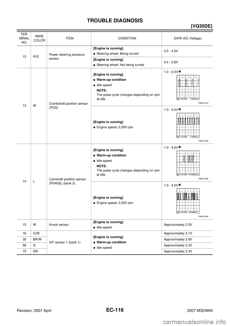
EC-116
[VQ35DE]
TROUBLE DIAGNOSIS
Revision: 2007 April2007 M35/M45
12 R/GPower steering pressure
sensor[Engine is running]�Steering wheel: Being turned0.5 - 4.5V
[Engine is running]
�Steering wheel: Not being turned0.4 - 0.8V
13 WCrankshaft position sensor
(POS)[Engine is running]
�Warm-up condition
�Idle speed
NOTE:
The pulse cycle changes depending on rpm
at idle1.0 - 2.0V
[Engine is running]
�Engine speed: 2,000 rpm1.0 - 2.0V
14 LCamshaft position sensor
(PHASE) (bank 2)[Engine is running]
�Warm-up condition
�Idle speed
NOTE:
The pulse cycle changes depending on rpm
at idle1.0 - 4.0V
[Engine is running]
�Engine speed: 2,000 rpm1.0 - 4.0V
15 W Knock sensor[Engine is running]
�Idle speedApproximately 2.5V
16 G/W
A/F sensor 1 (bank 1)[Engine is running]
�Warm-up condition
�Idle speedApproximately 3.1V
35 BR/WApproximately 2.6V
56 GApproximately 2.3V
75 GRApproximately 2.3V TER-
MINAL
NO.WIRE
COLORITEM CONDITION DATA (DC Voltage)
PBIB1041E
PBIB1042E
PBIB1039E
PBIB1040E
Page 1648 of 4647
![INFINITI M35 2007 Factory Service Manual TROUBLE DIAGNOSIS
EC-119
[VQ35DE]
C
D
E
F
G
H
I
J
K
L
MA
EC
Revision: 2007 April2007 M35/M45
50 W Throttle position sensor 1[Ignition switch: ON]
�Engine stopped
�Selector lever: D
�Accelerator pedal:](/manual-img/42/57024/w960_57024-1647.png "INFINITI M35 2007 Factory Service Manual TROUBLE DIAGNOSIS
EC-119
[VQ35DE]
C
D
E
F
G
H
I
J
K
L
MA
EC
Revision: 2007 April2007 M35/M45
50 W Throttle position sensor 1[Ignition switch: ON]
�Engine stopped
�Selector lever: D
�Accelerator pedal:")
TROUBLE DIAGNOSIS
EC-119
[VQ35DE]
C
D
E
F
G
H
I
J
K
L
MA
EC
Revision: 2007 April2007 M35/M45
50 W Throttle position sensor 1[Ignition switch: ON]
�Engine stopped
�Selector lever: D
�Accelerator pedal: Fully releasedMore than 0.36V
[Ignition switch: ON]
�Engine stopped
�Selector lever: D
�Accelerator pedal: Fully depressedLess than 4.75V
51 W Mass air flow sensor[Engine is running]
�Warm-up condition
�Idle speed0.9 - 1.2V
[Engine is running]
�Warm-up condition
�Engine speed: 2,500 rpm1.6 - 1.9V
55 WHeated oxygen sensor 2
(bank 2)[Engine is running]
�Revving engine from idle to 3,000 rpm
quickly after the following conditions are met
–Engine: After warming up
–Keeping the engine speed between 3,500
and 4,000 rpm for 1 minute and at idle for 1
minute under no load0 - Approximately 1.0V
57 GR/L
A/F sensor 1 (bank 2)[Engine is running]
�Warm-up condition
�Idle speedApproximately 2.6V
58 LG/BApproximately 2.3V
76 W/LApproximately 3.1V
77 YApproximately 2.3V
60
61
62
79
80
81V/W
P
Y/R
GR/R
GR/B
G/RIgnition signal No. 5
Ignition signal No. 3
Ignition signal No. 1
Ignition signal No. 6
Ignition signal No. 4
Ignition signal No. 2[Engine is running]
�Warm-up condition
�Idle speed
NOTE:
The pulse cycle changes depending on rpm
at idle0 - 0.2V
[Engine is running]
�Warm-up condition
�Engine speed: 2,000 rpm0.1 - 0.4V
66 BSensor ground
(Throttle position sensor)[Engine is running]
�Warm-up condition
�Idle speedApproximately 0V
67 B/W Sensor ground[Engine is running]
�Warm-up condition
�Idle speedApproximately 0V
68 L/YSensor power supply
(Power steering pressure
sensor)[Ignition switch: ON]Approximately 5V TER-
MINAL
NO.WIRE
COLORITEM CONDITION DATA (DC Voltage)
PBIB0044E
PBIB0045E
Page 1650 of 4647
![INFINITI M35 2007 Factory Service Manual TROUBLE DIAGNOSIS
EC-121
[VQ35DE]
C
D
E
F
G
H
I
J
K
L
MA
EC
Revision: 2007 April2007 M35/M45
98 RAccelerator pedal position
sensor 2[Ignition switch: ON]
�Engine stopped
�Accelerator pedal: Fully rel](/manual-img/42/57024/w960_57024-1649.png "INFINITI M35 2007 Factory Service Manual TROUBLE DIAGNOSIS
EC-121
[VQ35DE]
C
D
E
F
G
H
I
J
K
L
MA
EC
Revision: 2007 April2007 M35/M45
98 RAccelerator pedal position
sensor 2[Ignition switch: ON]
�Engine stopped
�Accelerator pedal: Fully rel")
TROUBLE DIAGNOSIS
EC-121
[VQ35DE]
C
D
E
F
G
H
I
J
K
L
MA
EC
Revision: 2007 April2007 M35/M45
98 RAccelerator pedal position
sensor 2[Ignition switch: ON]
�Engine stopped
�Accelerator pedal: Fully released0.20 - 0.55V
[Ignition switch: ON]
�Engine stopped
�Accelerator pedal: Fully depressed1.85 - 2.40V
99 YICC steering switch
(models with ICC system)[Ignition switch: ON]
�ICC steering switch: OFFApproximately 4.3V
[Ignition switch: ON]
�MAIN switch: PressedApproximately 0V
[Ignition switch: ON]
�CANCEL switch: PressedApproximately 1.3V
[Ignition switch: ON]
�RESUME/ACCELERATE switch: PressedApproximately 3.7V
[Ignition switch: ON]
�SET/COAST switch: PressedApproximately 3V
[Ignition switch: ON]
�DISTANCE switch: PressedApproximately 2.2V
99 YASCD steering switch
(models with ASCD system)[Ignition switch: ON]
�ASCD steering switch: OFFApproximately 4V
[Ignition switch: ON]
�MAIN switch: PressedApproximately 0V
[Ignition switch: ON]
�CANCEL switch: PressedApproximately 1V
[Ignition switch: ON]
�RESUME/ACCELERATE switch: PressedApproximately 3V
[Ignition switch: ON]
�SET/COAST switch: PressedApproximately 2V
101 V/R Stop lamp switch[Ignition switch: OFF]
�Brake pedal: Fully releasedApproximately 0V
[Ignition switch: OFF]
�Brake pedal: Slightly depressedBATTERY VOLTAGE
(11 - 14V)
102 G PNP switch[Ignition switch: ON]
�Selector lever: P or NApproximately 0V
[Ignition switch: ON]
�Selector lever: Except aboveBATTERY VOLTAGE
(11 - 14V)
104 O Throttle control motor relay[Ignition switch: OFF]BATTERY VOLTAGE
(11 - 14V)
[Ignition switch: ON]0 - 1.0V
106 LGAccelerator pedal position
sensor 1[Ignition switch: ON]
�Engine stopped
�Accelerator pedal: Fully released0.4 - 1.1V
[Ignition switch: ON]
�Engine stopped
�Accelerator pedal: Fully depressed3.7 - 4.8V TER-
MINAL
NO.WIRE
COLORITEM CONDITION DATA (DC Voltage)
![INFINITI M35 2007 Factory Service Manual EC-106
[VQ35DE]
TROUBLE DIAGNOSIS
Revision: 2007 April2007 M35/M45
: Vehicle front
1. Power steering pressure sensor 2. Intake valve timing control solenoid
valve3. Ignition coil harness connector
(](/manual-img/42/57024/w960_57024-1634.png "INFINITI M35 2007 Factory Service Manual EC-106
[VQ35DE]
TROUBLE DIAGNOSIS
Revision: 2007 April2007 M35/M45
: Vehicle front
1. Power steering pressure sensor 2. Intake valve timing control solenoid
valve3. Ignition coil harness connector
(")
![INFINITI M35 2007 Factory Service Manual TROUBLE DIAGNOSIS
EC-109
[VQ35DE]
C
D
E
F
G
H
I
J
K
L
MA
EC
Revision: 2007 April2007 M35/M45
1. ECM 2. Data link connector 3. Accelerator pedal position sensor
4. Stop lamp switch 5. ICC brake switch](/manual-img/42/57024/w960_57024-1637.png "INFINITI M35 2007 Factory Service Manual TROUBLE DIAGNOSIS
EC-109
[VQ35DE]
C
D
E
F
G
H
I
J
K
L
MA
EC
Revision: 2007 April2007 M35/M45
1. ECM 2. Data link connector 3. Accelerator pedal position sensor
4. Stop lamp switch 5. ICC brake switch")