Page 3996 of 4647
 with the marking position (B)
of gear housing assembly.
–Install slit part of")
STEERING COLUMN
PS-15
C
D
E
F
H
I
J
K
L
MA
B
PS
Revision: 2007 April2007 M35/M45
–Align rear cover cap projection (A) with the marking position (B)
of gear housing assembly.
–Install slit part of lower joint (C) aligning with the projection (A) of
rear cover cap (1). Make sure that the slit part of lower joint (C)
is aligned with projection (A) of rear cover cap (1) and the mark-
ing position (B) of gear housing assembly.
�Adjust neutral position of steering angle sensor. Refer to BRC-6,
"Adjustment of Steering Angle Sensor Neutral Position" .
REMOVAL OF STEERING COLUMN ASSEMBLY
1. Set vehicle to the straight-ahead position.
2. Remove driver air bag module. Refer to SRS-42, "
DRIVER AIR BAG MODULE" .
3. Remove steering wheel. Refer to PS-12, "
Removal and Installation" .
4. Remove steering column cover. Refer to IP-10, "
INSTRUMENT PANEL ASSEMBLY" .
5. Remove combination switch & spiral cable. Refer to SRS-44, "
SPIRAL CABLE" .
6. Remove instrument driver lower panel. Refer to IP-10, "
INSTRUMENT PANEL ASSEMBLY" .
7. Remove fixing bolts of knee protector (1), then remove knee
protector (1) from vehicle.
8. Remove low tire pressure warning control unit. Refer to WT-40,
"Low Tire Pressure Warning Control Unit" .
9. Disconnect each switch connectors installed to steering column
assembly, and then disconnect harness from steering column
assembly.
10. Remove fixing bolt of upper joint (1) (steering column assembly
side).
11. Remove steering column assembly mounting bolts and nut, then
remove steering column assembly from vehicle.
SGIA1175E
SGIA1176E
SGIA1182E
Page 3997 of 4647

PS-16
STEERING COLUMN
Revision: 2007 April2007 M35/M45
INSPECTION AFTER REMOVAL
�Check each part of steering column assembly for damage or other malfunctions. Replace if there are.
�Measure the length L as shown in the figure if vehicle has been
involved in a minor collision. Replace steering column assembly
if outside the standard.
�Measure steering column assembly rotating torque using preload gauge [SST: ST3127S000]. Replace
steering column assembly if outside the standard.
INSTALLATION OF STEERING COLUMN ASSEMBLY
�Installation is the reverse order of removal. For tightening torque, refer to PS-13, "COMPONENTS" .
�When installing upper joint, the angle which upper joint yoke (1)
forms with shaft center groove (A) should be at 90°.
�Adjust neutral position of steering angle sensor. Refer to BRC-6,
"Adjustment of Steering Angle Sensor Neutral Position" .
INSPECTION AFTER INSTALLATION
Make sure that steering wheel operates smoothly by turning several times from full left stop to full right stop.
SGIA1177E
Steering column length LTelescopic maximum 551 – 555 mm (21.69 – 21.85 in)
Telescopic minimum 591 – 595 mm (23.27 – 23.43 in)
Rotating torque : 0 – 0.2 N·m (0 – 0.02 kg-m, 0 – 1 in-lb)
SGIA1290E
Page 3998 of 4647

STEERING COLUMN
PS-17
C
D
E
F
H
I
J
K
L
MA
B
PS
Revision: 2007 April2007 M35/M45
Disassembly and AssemblyNGS000DB
COMPONENTS
DISASSEMBLY
1. Remove fixing screws of telescopic sensor, and then remove telescopic sensor from steering column.
2. Remove fixing screw of bracket, and then remove bracket from telescopic motor.
3. Remove fixing bolt of telescopic motor, and then remove telescopic motor from steering column.
4. Remove fixing screws of tilt sensor, and then remove tilt sensor from steering column.
5. Remove fixing bolt of tilt motor, and then remove tilt motor from steering column.
6. Remove fixing screws of brackets, and then remove brackets from steering column.
INSPECTION AFTER DISASSEMBLY
Check component parts for damage or other malfunctions. Replace if there are.
ASSEMBLY
Assembly is the reverse order of disassembly. For tightening torque, refer to PS-17, "COMPONENTS" .
1. Bracket 2. Bracket 3. Steering column
4. Telescopic motor 5. Bracket 6. Telescopic sensor
7. Tilt sensor 8. Tilt motor 9. Bracket
10. Bracket
Refer to GI-11, "
Components" , for the symbols in the figure.
SGIA1634E
Page 4001 of 4647

PS-20
POWER STEERING GEAR AND LINKAGE
Revision: 2007 April2007 M35/M45
8. Remove steering hydraulic piping bracket from front suspension member. Refer to PS-39, "HYDRAULIC
LINE" .
9. Remove power steering solenoid valve harness connector. Refer to PS-21, "
COMPONENTS" .
10. Remove rack stay (2WD) or front cross bar (AWD). Refer to FSU-8, "
Components" , FSU-26, "Compo-
nents" .
11. Remove mounting bolts and nuts of steering gear assembly, and then remove steering gear assembly
from vehicle.
INSTALLATION
Installation is the reverse order of removal. For tightening torque, refer to PS-19, "COMPONENTS" .
�When installing lower joint to steering gear assembly, follow the procedure listed below.
–Set rack of steering gear in the neutral position.
NOTE:
To get the neutral position of rack, turn gear-sub assembly and measure the distance of inner socket, and
then measure the intermediate position of the distance.
–Align rear cover cap projection (A) with the marking position (B)
of gear housing assembly.
–Install slit part of lower joint (C) aligning with the projection (A) of
rear cover cap (1). Make sure that the slit part of lower joint (C)
is aligned with both the projection (A) of rear cover cap (1) and
the marking position (B) of gear housing assembly.
�After installation, bleed air from the steering hydraulic system.
Refer to PS-8, "
Air Bleeding Hydraulic System" .
�Perform final tightening of nuts and bolts on each part under
unladen conditions with tires on level ground when removing
steering gear assembly. Check wheel alignment. Refer to FSU-
6, "Wheel Alignment Inspection" , FSU-24, "Wheel Alignment
Inspection" .
�Adjust neutral position of steering angle sensor after checking wheel alignment. Refer to BRC-6, "Adjust-
ment of Steering Angle Sensor Neutral Position" .
INSPECTION AFTER INSTALLATION
Make sure that steering wheel operates smoothly by turning several times from full left stop to full right stop.
SGIA1175E
Page 4021 of 4647
PS-40
HYDRAULIC LINE
Revision: 2007 April2007 M35/M45
10. Eye-bolt 11. Copper washer 12. Eye-joint (assembled to high-pres-
sure side hose)
13. Pressure sensor 14. Oil pump bracket
Refer to GI-11, "
Components" , and the followings for the symbols in the figure.
: Apply power steering fluid.
Page 4022 of 4647
HYDRAULIC LINE
PS-41
C
D
E
F
H
I
J
K
L
MA
B
PS
Revision: 2007 April2007 M35/M45
COMPONENTS (VQ35DE AWD MODELS)
1. Reservoir tank 2. Reservoir tank bracket 3. Suction hose
4. High-pressure hose 5. Oil pump assembly 6. Steering gear assembly
7. Low pressure piping 8. High pressure piping 9. O-ring
10. Eye-bolt 11. Copper washer 12. Eye-joint (assembled to high-pres-
sure side hose)
13. Pressure sensor 14. Oil pump bracket
SGIA1191E
Page 4024 of 4647
HYDRAULIC LINE
PS-43
C
D
E
F
H
I
J
K
L
MA
B
PS
Revision: 2007 April2007 M35/M45
COMPONENTS (VK45DE MODELS)
1. Reservoir tank 2. Reservoir tank bracket 3. Suction hose
4. High-pressure hose 5. Oil pump assembly 6. Steering gear assembly
7. Low pressure piping 8. High pressure piping 9. O-ring
10. Eye-bolt 11. Copper washer 12. Eye-joint (assembled to high-pres-
sure side hose)
13. Pressure sensor 14. Oil pump bracket
SGIA1391E
Page 4025 of 4647
PS-44
HYDRAULIC LINE
Revision: 2007 April2007 M35/M45
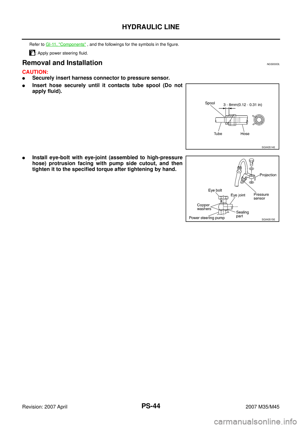
Removal and InstallationNGS000DL
CAUTION:
�Securely insert harness connector to pressure sensor.
�Insert hose securely until it contacts tube spool (Do not
apply fluid).
�Install eye-bolt with eye-joint (assembled to high-pressure
hose) protrusion facing with pump side cutout, and then
tighten it to the specified torque after tightening by hand.
Refer to GI-11, "Components" , and the followings for the symbols in the figure.
: Apply power steering fluid.
SGIA0514E
SGIA0515E

13. Pressure sensor 14. Oil pump bracket
Refer to GI-11, \"")

1. Reservoir tank 2. Reservoir tank bracket 3. Suction hose
4. High-pressure hose 5. Oil")

1. Reservoir tank 2. Reservoir tank bracket 3. Suction hose
4. High-pressure hose 5. Oil pump")