Page 3611 of 4647

LT-160
ACTIVE AFS
Revision: 2007 April2007 M35/M45
Symptom ChartNKS003QN
CAUTION:
The low beam headlamps performs small movements when AFS control unit detects the engine start.
This is normal with initialization of swivel actuator by AFS control unit.
SymptomAFS OFF
indicatorCausal system Reference
�AFS operates, but cannot judge normal/
abnormal.
(AFS function test)NormalCheck swivel operation.LT- 1 8 2 , "AFS
Operation
Check (Func-
tion Test)"
Check steering angle sensor neutral point (straight-ahead
position).
�Auto aiming operates, but cannot judge
normal/abnormal.
(Auto aiming function test)NormalCheck auto aiming operation.LT- 1 8 4 , "Auto
Aiming Opera-
tion Check
(Function
Test)"
Check height sensor signal value recognized by AFS con-
trol unit at unloaded vehicle position.
Check height sensor signal and aiming motor drive signal.
�Neither AFS operates nor auto aiming
operates.BlinkingCheck AFS control unit self-diagnostic results. LT- 1 5 3 ,
"SELF-DIAG
RESULTS"
Check AFS control unit power supply and ground circuit.
NOTE:
Check only when “ADAPTIVE LIGHT” is not displayed on
CONSULT-II “SELECT SYSTEM” screen.LT- 1 5 1 , "Pre-
liminary
Check"
�AFS does not operate.
(Auto aiming operation is normal.)Blinking Check AFS control unit self-diagnostic results. LT- 1 5 3 ,
"SELF-DIAG
RESULTS"
Illuminated Check AFS switch system circuit.LT- 1 8 6 , "
AFS
Switch Does
Not Operate"
�Auto aiming does not operate.
(AFS operation is normal.)NormalCheck AFS control unit self-diagnostic results. LT- 1 5 3 ,
"SELF-DIAG
RESULTS"
Check aiming motor system circuit.LT- 1 8 8 , "
Auto
Aiming Does
Not Operate
(Check Aiming
Motor System
Circuit)"
�Auto aiming operates in the reverse way.
(Lowering vehicle height angles light
axis up.)Normal Replace AFS control unit.LT- 1 9 2 , "Removal and
Installation of
AFS Control
Unit"
�AFS OFF indicator does not illuminate.
(AFS operation and auto aiming opera-
tion are normal.)Not
illuminatedCheck circuit between unified meter and A/C amp. and
combination meter.LT- 1 9 1 , "
AFS
OFF Indicator
Does Not
Operate"�AFS OFF indicator blinks.
(AFS operation and auto aiming opera-
tion are normal.)BlinkingCheck receive state of AFS off indicator signal from uni-
fied meter and A/C amp.
�AFS cannot be cancelled.
(AFS switch does not operate.)Normal Check AFS switch system circuit.LT- 1 8 6 , "AFS
Switch Does
Not Operate"
Page 3612 of 4647
ACTIVE AFS
LT-161
C
D
E
F
G
H
I
J
L
MA
B
LT
Revision: 2007 April2007 M35/M45
DTC B2503 SWIVEL ACTUATOR RHNKS003QO
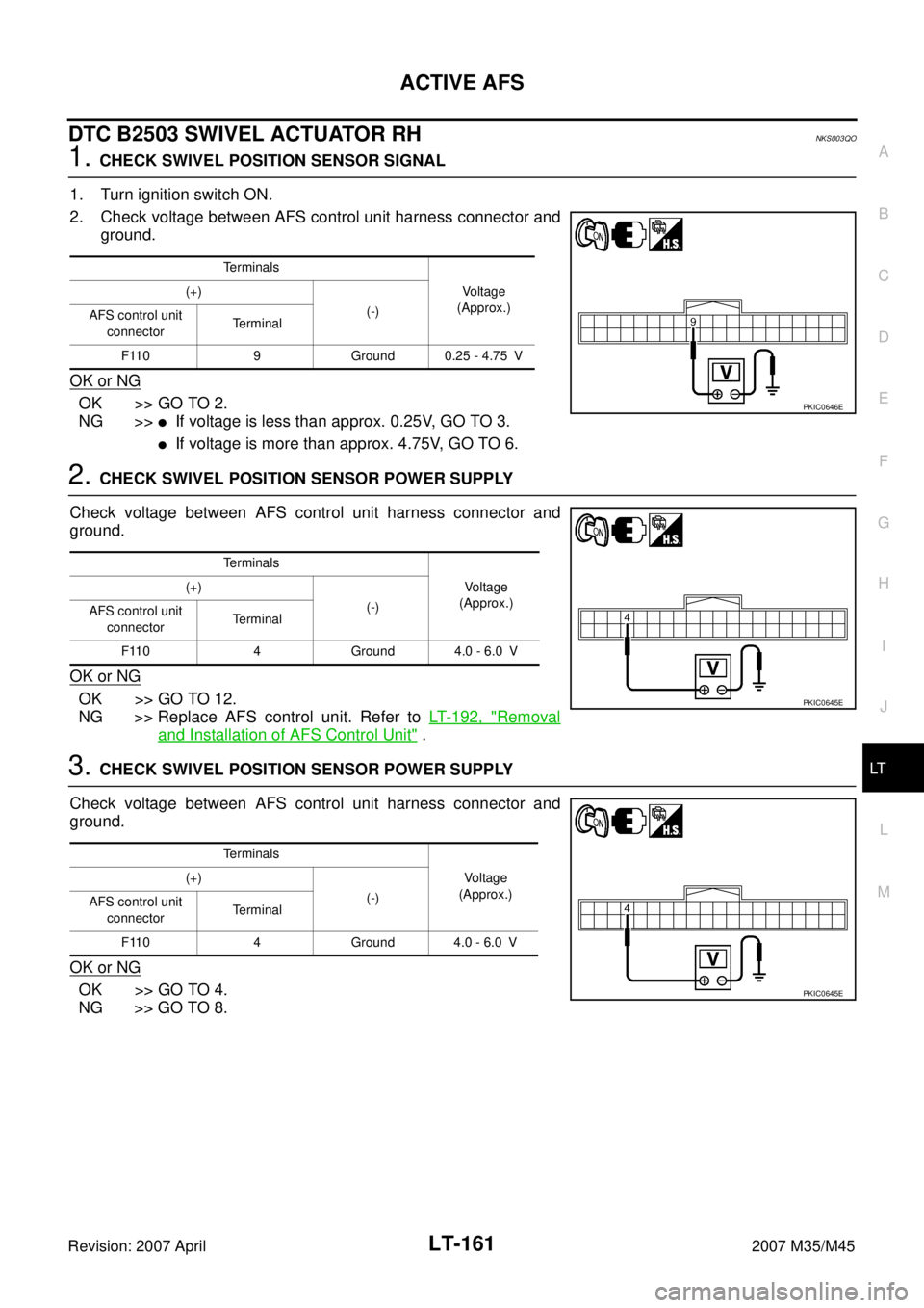
1. CHECK SWIVEL POSITION SENSOR SIGNAL
1. Turn ignition switch ON.
2. Check voltage between AFS control unit harness connector and
ground.
OK or NG
OK >> GO TO 2.
NG >>
�If voltage is less than approx. 0.25V, GO TO 3.
�If voltage is more than approx. 4.75V, GO TO 6.
2. CHECK SWIVEL POSITION SENSOR POWER SUPPLY
Check voltage between AFS control unit harness connector and
ground.
OK or NG
OK >> GO TO 12.
NG >> Replace AFS control unit. Refer to LT- 1 9 2 , "
Removal
and Installation of AFS Control Unit" .
3. CHECK SWIVEL POSITION SENSOR POWER SUPPLY
Check voltage between AFS control unit harness connector and
ground.
OK or NG
OK >> GO TO 4.
NG >> GO TO 8.
Terminals
Voltage
(Approx.) (+)
(-)
AFS control unit
connectorTerminal
F110 9 Ground 0.25 - 4.75 V
PKIC0646E
Terminals
Voltage
(Approx.) (+)
(-)
AFS control unit
connectorTerminal
F110 4 Ground 4.0 - 6.0 V
PKIC0645E
Terminals
Voltage
(Approx.) (+)
(-)
AFS control unit
connectorTerminal
F110 4 Ground 4.0 - 6.0 V
PKIC0645E
Page 3613 of 4647
LT-162
ACTIVE AFS
Revision: 2007 April2007 M35/M45
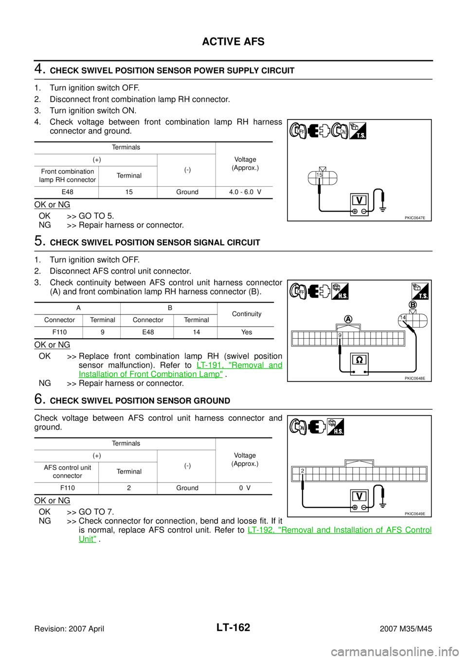
4. CHECK SWIVEL POSITION SENSOR POWER SUPPLY CIRCUIT
1. Turn ignition switch OFF.
2. Disconnect front combination lamp RH connector.
3. Turn ignition switch ON.
4. Check voltage between front combination lamp RH harness
connector and ground.
OK or NG
OK >> GO TO 5.
NG >> Repair harness or connector.
5. CHECK SWIVEL POSITION SENSOR SIGNAL CIRCUIT
1. Turn ignition switch OFF.
2. Disconnect AFS control unit connector.
3. Check continuity between AFS control unit harness connector
(A) and front combination lamp RH harness connector (B).
OK or NG
OK >> Replace front combination lamp RH (swivel position
sensor malfunction). Refer to LT- 1 9 1 , "
Removal and
Installation of Front Combination Lamp" .
NG >> Repair harness or connector.
6. CHECK SWIVEL POSITION SENSOR GROUND
Check voltage between AFS control unit harness connector and
ground.
OK or NG
OK >> GO TO 7.
NG >> Check connector for connection, bend and loose fit. If it
is normal, replace AFS control unit. Refer to LT- 1 9 2 , "
Removal and Installation of AFS Control
Unit" .
Te r m i n a l s
Voltage
(Approx.) (+)
(-)
Front combination
lamp RH connectorTerminal
E48 15 Ground 4.0 - 6.0 V
PKIC0647E
AB
Continuity
Connector Terminal Connector Terminal
F110 9 E48 14 Yes
PKIC0648E
Te r m i n a l s
Voltage
(Approx.) (+)
(-)
AFS control unit
connectorTerminal
F110 2 Ground 0 V
PKIC0649E
Page 3614 of 4647
ACTIVE AFS
LT-163
C
D
E
F
G
H
I
J
L
MA
B
LT
Revision: 2007 April2007 M35/M45
7. CHECK SWIVEL POSITION SENSOR GROUND CIRCUIT
1. Turn ignition switch OFF.
2. Disconnect AFS control unit connector and front combination lamp RH connector.
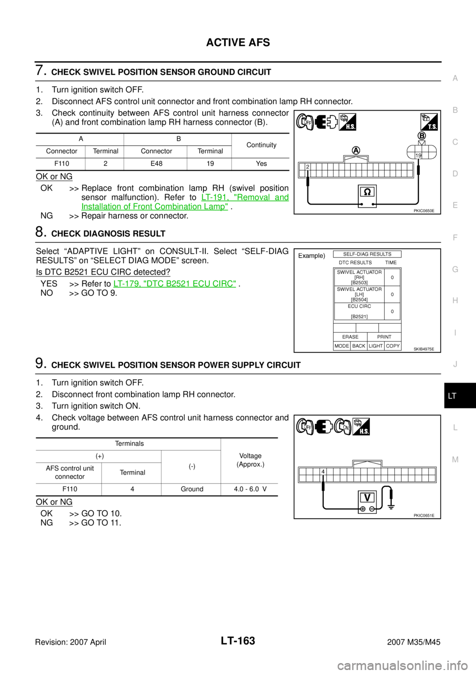
3. Check continuity between AFS control unit harness connector
(A) and front combination lamp RH harness connector (B).
OK or NG
OK >> Replace front combination lamp RH (swivel position
sensor malfunction). Refer to LT- 1 9 1 , "
Removal and
Installation of Front Combination Lamp" .
NG >> Repair harness or connector.
8. CHECK DIAGNOSIS RESULT
Select “ADAPTIVE LIGHT” on CONSULT-II. Select “SELF-DIAG
RESULTS” on “SELECT DIAG MODE” screen.
Is DTC B2521 ECU CIRC detected?
YES >> Refer to LT- 1 7 9 , "DTC B2521 ECU CIRC" .
NO >> GO TO 9.
9. CHECK SWIVEL POSITION SENSOR POWER SUPPLY CIRCUIT
1. Turn ignition switch OFF.
2. Disconnect front combination lamp RH connector.
3. Turn ignition switch ON.
4. Check voltage between AFS control unit harness connector and
ground.
OK or NG
OK >> GO TO 10.
NG >> GO TO 11.
AB
Continuity
Connector Terminal Connector Terminal
F110 2 E48 19 Yes
PKIC0650E
SKIB4975E
Terminals
Voltage
(Approx.) (+)
(-)
AFS control unit
connectorTerminal
F110 4 Ground 4.0 - 6.0 V
PKIC0651E
Page 3615 of 4647
LT-164
ACTIVE AFS
Revision: 2007 April2007 M35/M45
10. CHECK SWIVEL POSITION SENSOR SIGNAL CIRCUIT (SHORT CIRCUIT)
1. Turn ignition switch OFF.
2. Disconnect AFS control unit connector.
3. Check continuity between AFS control unit harness connector
and ground.
OK or NG
OK >> Replace front combination lamp RH (swivel position
sensor malfunction). Refer to LT- 1 9 1 , "
Removal and
Installation of Front Combination Lamp" .
NG >> Repair harness or connector.
11 . CHECK SWIVEL POSITION SENSOR POWER SUPPLY CIRCUIT (SHORT CIRCUIT)
1. Turn ignition switch OFF.
2. Disconnect AFS control unit connector.
3. Check continuity between AFS control unit harness connector
and ground.
OK or NG
OK >> Replace AFS control unit. Refer to LT- 1 9 2 , "Removal
and Installation of AFS Control Unit" .
NG >> Repair harness or connector.
AFS control unit
connectorTerminal
GroundContinuity
F110 9 No
SKIB4968E
AFS control unit
connectorTerminal
GroundContinuity
F110 4 No
PKIC0652E
Page 3619 of 4647
LT-168
ACTIVE AFS
Revision: 2007 April2007 M35/M45
DTC B2504 SWIVEL ACTUATOR LHNKS003QP
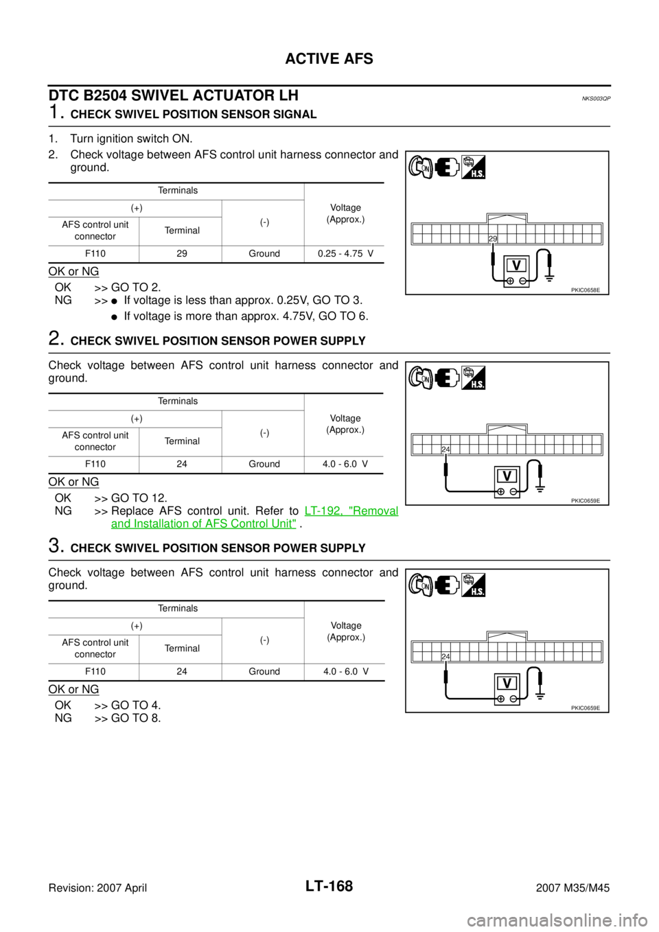
1. CHECK SWIVEL POSITION SENSOR SIGNAL
1. Turn ignition switch ON.
2. Check voltage between AFS control unit harness connector and
ground.
OK or NG
OK >> GO TO 2.
NG >>
�If voltage is less than approx. 0.25V, GO TO 3.
�If voltage is more than approx. 4.75V, GO TO 6.
2. CHECK SWIVEL POSITION SENSOR POWER SUPPLY
Check voltage between AFS control unit harness connector and
ground.
OK or NG
OK >> GO TO 12.
NG >> Replace AFS control unit. Refer to LT- 1 9 2 , "
Removal
and Installation of AFS Control Unit" .
3. CHECK SWIVEL POSITION SENSOR POWER SUPPLY
Check voltage between AFS control unit harness connector and
ground.
OK or NG
OK >> GO TO 4.
NG >> GO TO 8.
Te r m i n a l s
Voltage
(Approx.) (+)
(-)
AFS control unit
connectorTerminal
F110 29 Ground 0.25 - 4.75 V
PKIC0658E
Te r m i n a l s
Voltage
(Approx.) (+)
(-)
AFS control unit
connectorTerminal
F110 24 Ground 4.0 - 6.0 V
PKIC0659E
Te r m i n a l s
Voltage
(Approx.) (+)
(-)
AFS control unit
connectorTerminal
F110 24 Ground 4.0 - 6.0 V
PKIC0659E
Page 3620 of 4647
ACTIVE AFS
LT-169
C
D
E
F
G
H
I
J
L
MA
B
LT
Revision: 2007 April2007 M35/M45
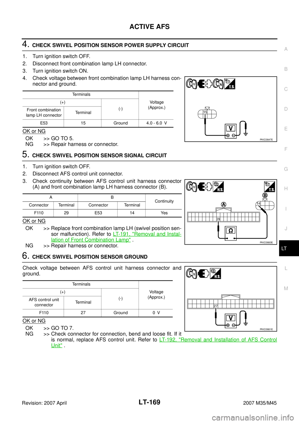
4. CHECK SWIVEL POSITION SENSOR POWER SUPPLY CIRCUIT
1. Turn ignition switch OFF.
2. Disconnect front combination lamp LH connector.
3. Turn ignition switch ON.
4. Check voltage between front combination lamp LH harness con-
nector and ground.
OK or NG
OK >> GO TO 5.
NG >> Repair harness or connector.
5. CHECK SWIVEL POSITION SENSOR SIGNAL CIRCUIT
1. Turn ignition switch OFF.
2. Disconnect AFS control unit connector.
3. Check continuity between AFS control unit harness connector
(A) and front combination lamp LH harness connector (B).
OK or NG
OK >> Replace front combination lamp LH (swivel position sen-
sor malfunction). Refer to LT- 1 9 1 , "
Removal and Instal-
lation of Front Combination Lamp" .
NG >> Repair harness or connector.
6. CHECK SWIVEL POSITION SENSOR GROUND
Check voltage between AFS control unit harness connector and
ground.
OK or NG
OK >> GO TO 7.
NG >> Check connector for connection, bend and loose fit. If it
is normal, replace AFS control unit. Refer to LT- 1 9 2 , "
Removal and Installation of AFS Control
Unit" .
Terminals
Voltage
(Approx.) (+)
(-)
Front combination
lamp LH connectorTerminal
E53 15 Ground 4.0 - 6.0 V
PKIC0647E
AB
Continuity
Connector Terminal Connector Terminal
F110 29 E53 14 Yes
PKIC0660E
Terminals
Voltage
(Approx.) (+)
(-)
AFS control unit
connectorTerminal
F110 27 Ground 0 V
PKIC0661E
Page 3621 of 4647
LT-170
ACTIVE AFS
Revision: 2007 April2007 M35/M45
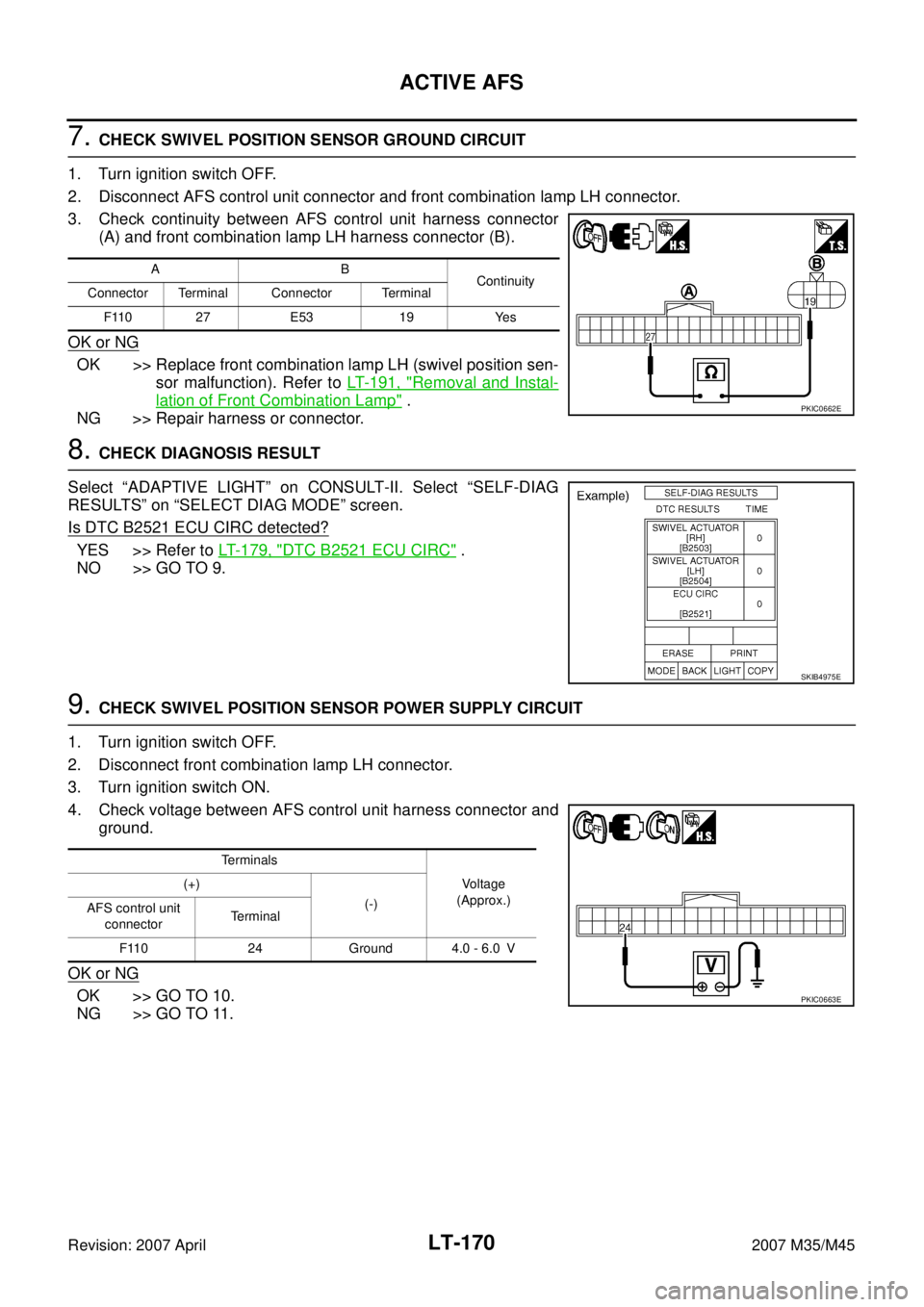
7. CHECK SWIVEL POSITION SENSOR GROUND CIRCUIT
1. Turn ignition switch OFF.
2. Disconnect AFS control unit connector and front combination lamp LH connector.
3. Check continuity between AFS control unit harness connector
(A) and front combination lamp LH harness connector (B).
OK or NG
OK >> Replace front combination lamp LH (swivel position sen-
sor malfunction). Refer to LT- 1 9 1 , "
Removal and Instal-
lation of Front Combination Lamp" .
NG >> Repair harness or connector.
8. CHECK DIAGNOSIS RESULT
Select “ADAPTIVE LIGHT” on CONSULT-II. Select “SELF-DIAG
RESULTS” on “SELECT DIAG MODE” screen.
Is DTC B2521 ECU CIRC detected?
YES >> Refer to LT- 1 7 9 , "DTC B2521 ECU CIRC" .
NO >> GO TO 9.
9. CHECK SWIVEL POSITION SENSOR POWER SUPPLY CIRCUIT
1. Turn ignition switch OFF.
2. Disconnect front combination lamp LH connector.
3. Turn ignition switch ON.
4. Check voltage between AFS control unit harness connector and
ground.
OK or NG
OK >> GO TO 10.
NG >> GO TO 11.
AB
Continuity
Connector Terminal Connector Terminal
F110 27 E53 19 Yes
PKIC0662E
SKIB4975E
Te r m i n a l s
Voltage
(Approx.) (+)
(-)
AFS control unit
connectorTerminal
F110 24 Ground 4.0 - 6.0 V
PKIC0663E