Page 2957 of 4647
EC-1428
[VK45DE]
REFRIGERANT PRESSURE SENSOR
Revision: 2007 April2007 M35/M45
7. CHECK REFRIGERANT PRESSURE SENSOR INPUT SIGNAL CIRCUIT FOR OPEN AND SHORT
1. Check harness continuity between ECM terminal 70 and refrigerant pressure sensor terminal 2.
Refer to Wiring Diagram.
2. Also check harness for short to ground and short to power.
OK or NG
OK >> GO TO 9.
NG >> GO TO 8.
8. DETECT MALFUNCTIONING PART
Check the following.
�Harness connectors E11, F2
�Harness for open or short between ECM and refrigerant pressure sensor
>> Repair open circuit or short to ground or short to power in harness or connectors.
9. CHECK INTERMITTENT INCIDENT
Refer to EC-857, "
TROUBLE DIAGNOSIS FOR INTERMITTENT INCIDENT" .
OK or NG
OK >> Replace refrigerant pressure sensor.
NG >> Repair or replace.
Removal and InstallationNBS005QA
REFRIGERANT PRESSURE SENSOR
Refer to ATC-166, "Removal and Installation of Refrigerant Pressure Sensor" . Continuity should exist.
Page 2958 of 4647
![INFINITI M35 2007 Factory Service Manual VIAS
EC-1429
[VK45DE]
C
D
E
F
G
H
I
J
K
L
MA
EC
Revision: 2007 April2007 M35/M45
VIASPFP:14956
DescriptionNBS005PK
SYSTEM DESCRIPTION
*: The ECM determines the start signal status by the signals of en](/manual-img/42/57024/w960_57024-2957.png "INFINITI M35 2007 Factory Service Manual VIAS
EC-1429
[VK45DE]
C
D
E
F
G
H
I
J
K
L
MA
EC
Revision: 2007 April2007 M35/M45
VIASPFP:14956
DescriptionNBS005PK
SYSTEM DESCRIPTION
*: The ECM determines the start signal status by the signals of en")
VIAS
EC-1429
[VK45DE]
C
D
E
F
G
H
I
J
K
L
MA
EC
Revision: 2007 April2007 M35/M45
VIASPFP:14956
DescriptionNBS005PK
SYSTEM DESCRIPTION
*: The ECM determines the start signal status by the signals of engine speed and battery voltage.
When the engine is running at low or medium speed, the power valve is fully closed. Under this condition, the
effective suction port length is equivalent to the total length of the intake manifold collector's suction port
including the intake valve. This long suction port provides increased air intake which results in improved suc-
tion efficiency and higher torque generation.
The surge tank and one-way valve are provided. When engine is running at high speed, the ECM sends the
signal to the VIAS control solenoid valve. This signal introduces the intake manifold vacuum into the power
valve actuator and therefore opens the power valve to two suction passages together in the collector.
Under this condition, the effective port length is equivalent to the length of the suction port provided indepen-
dently for each cylinder. This shortened port length results in enhanced engine output with reduced suction
resistance under high speeds.
The power valve is always open regardless of the engine speed when gear position is in N or P.
Sensor Input signal to ECM ECM function Actuator
Crankshaft position sensor (POS)
Camshaft position sensor (PHASE)Engine speed*
VIAS control VIAS control solenoid valve Mass air flow sensor Amount of intake air
Throttle position sensor Throttle position
Accelerator pedal position sensor Accelerator pedal position
Battery Battery voltage*
Engine coolant temperature sensor Engine coolant temperature
PBIB1876E
Page 2969 of 4647
![INFINITI M35 2007 Factory Service Manual EC-1440
[VK45DE]
SERVICE DATA AND SPECIFICATIONS (SDS)
Revision: 2007 April2007 M35/M45
SERVICE DATA AND SPECIFICATIONS (SDS)PFP:00030
Fuel PressureNBS005QT
Idle Speed and Ignition TimingNBS005QU
*: U](/manual-img/42/57024/w960_57024-2968.png "INFINITI M35 2007 Factory Service Manual EC-1440
[VK45DE]
SERVICE DATA AND SPECIFICATIONS (SDS)
Revision: 2007 April2007 M35/M45
SERVICE DATA AND SPECIFICATIONS (SDS)PFP:00030
Fuel PressureNBS005QT
Idle Speed and Ignition TimingNBS005QU
*: U")
EC-1440
[VK45DE]
SERVICE DATA AND SPECIFICATIONS (SDS)
Revision: 2007 April2007 M35/M45
SERVICE DATA AND SPECIFICATIONS (SDS)PFP:00030
Fuel PressureNBS005QT
Idle Speed and Ignition TimingNBS005QU
*: Under the following conditions:
�Air conditioner switch: OFF
�Electric load: OFF (Lights, heater fan & rear window defogger)
�Steering wheel: Kept in straight-ahead position
Calculated Load ValueNBS005QV
Mass Air Flow SensorNBS005QW
*: Engine is warmed up to normal operating temperature and running under no load.
Intake Air Temperature SensorNBS005QX
Engine Coolant Temperature SensorNBS005QY
Fuel Tank Temperature SensorNBS005QZ
Crankshaft Position Sensor (POS)NBS005R0
Refer to EC-1081, "Component Inspection" .
Camshaft Position Sensor (PHASE)NBS005R1
Refer to EC-1088, "Component Inspection" .
A/F Sensor 1 HeaterNBS005R2
Fuel pressure at idling kPa (kg/cm2 , psi)Approximately 350 (3.57, 51)
Target idle speed No load* (in P or N position) 650 ± 50 rpm
Air conditioner: ON In P or N position 650 rpm or more
Ignition timing In P or N position 12° ± 5° BTDC
Condition Calculated load value% (Using CONSULT-II or GST)
At idle14 - 33
At 2,500 rpm12 - 25
Supply voltageBattery voltage (11 - 14V)
Output voltage at idle0.9 - 1.2V*
Mass air flow (Using CONSULT-II or GST)2.0 - 6.0 g·m/sec at idle*
7.0 - 20.0 g·m/sec at 2,500 rpm*
Temperature °C (°F) Resistance kΩ
25 (77)1.800 - 2.200
Temperature °C (°F) Resistance kΩ
20 (68)2.1 - 2.9
50 (122)0.68 - 1.00
90 (194)0.236 - 0.260
Temperature °C (°F) Resistance kΩ
20 (68)2.3 - 2.7
50 (122)0.79 - 0.90
Resistance [at 25°C (77°F)] 2.3 - 4.3Ω
Page 2970 of 4647
SERVICE DATA AND SPECIFICATIONS (SDS)
EC-1441
[VK45DE]
C
D
E
F
G
H
I
J
K
L
MA
EC
Revision: 2007 April2007 M35/M45
Heated Oxygen Sensor 2 HeaterNBS005R3
Throttle Control MotorNBS005R4
Fuel InjectorNBS005R5
Fuel PumpNBS005R6
Resistance [at 25°C (77°F)] 5.0 - 7.0Ω
Resistance [at 25°C (77°F)] Approximately 1 - 15Ω
Resistance [at 10 - 60°C (50 - 140°F)] 13.5 - 17.5Ω
Resistance [at 25°C (77°F)] 0.2 - 5.0Ω
Page 3031 of 4647

EX-2
PREPARATION
Revision: 2007 April2007 M35/M45
PREPARATIONPFP:00002
Special Service ToolsNBS005RH
The actual shapes of Kent-Moore tools may differ from those of special service tools illustrated here.
Commercial Service ToolsNBS005RI
Tool number
(Kent-Moore No.)
Tool nameDescription
KV10117100
(J3647-A)
Heated oxygen sensor wrenchLoosening or tightening heated oxygen
sensor 2 (VQ35DE)
For 22 mm (0.87 in) width hexagon nut
KV10114400
(J38365)
Heated oxygen sensor wrenchLoosening or tightening heated oxygen
sensor 2 (VK45DE)
For 22 mm (0.87 in) width hexagon nut
NT379
S-NT636
(Kent-Moore No.)
Tool nameDescription
a: (J-43897-18)
b: (J-43897-12)
Heated oxygen sensor thread cleanerReconditioning the exhaust system threads
before installing a new heated oxygen sensor
(Use with anti-seize lubricant shown below.)
a: J-43897-18 (18 mm dia.) for zirconia
heated oxygen sensor
b: J-43897-12 (12 mm dia.) for titania
heated oxygen sensor
(—)
Anti-seize lubricant (Permatex 133AR
or equivalent meeting MIL
specification MIL-A-907)Lubricating heated oxygen sensor thread
cleaner when reconditioning exhaust system
threads
( — )
Power toolLoosening bolts and nuts
AEM488
AEM489
PBIC0190E
Page 3033 of 4647
EX-4
EXHAUST SYSTEM
Revision: 2007 April2007 M35/M45
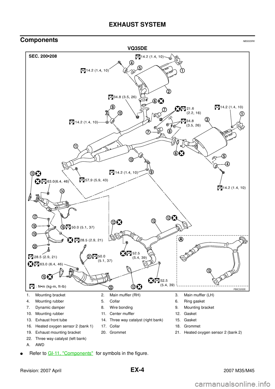
ComponentsNBS005RK
VQ35DE
�Refer to GI-11, "Components" for symbols in the figure.
PBIC3202E
1. Mounting bracket 2. Main muffler (RH) 3. Main muffler (LH)
4. Mounting rubber 5. Collar 6. Ring gasket
7. Dynamic damper 8. Wire bonding 9. Mounting bracket
10. Mounting rubber 11. Center muffler 12. Gasket
13. Exhaust front tube 14. Three way catalyst (right bank) 15. Gasket
16. Heated oxygen sensor 2 (bank 1) 17. Collar 18. Grommet
19. Exhaust mounting bracket 20. Grommet 21. Heated oxygen sensor 2 (bank 2)
22. Three way catalyst (left bank)
A. AWD
Page 3034 of 4647

EXHAUST SYSTEM
EX-5
C
D
E
F
G
H
I
J
K
L
MA
EX
Revision: 2007 April2007 M35/M45
Removal and InstallationNBS005RL
CAUTION:
�Be sure to use genuine exhaust system parts or equivalents which are specially designed for heat
resistance, corrosion resistance, and shape.
�Perform the operation with the exhaust system fully cooled down because the system will be hot
just after engine stops.
�Be careful not to cut your hand on the heat insulator edge.
REMOVAL
�Disconnect each joint and mounting using power tool.
�Remove heated oxygen sensor 2 as follows:
–Using heated oxygen sensor wrench (SST), removal heated
oxygen sensor 2.
CAUTION:
Be careful not to damage heated oxygen sensor 2.
INSTALLATION
Note the following, and install in the reverse order of removal.
�Check for deformation of the grommets (18 and 20 of Components).
�Insert the collar (17 of Components) vertically.
�Install the collar (5 of Components) with its lower surface horizontal.
�Temporarily tighten nuts and bolts when installing exhaust pipe assembly. Tighten them to the specified
torque when connecting the vehicle rear to the vehicle front.
CAUTION:
�Always replace exhaust tube gaskets with new ones when reassembling.
�Discard any heated oxygen sensor which has been dropped onto a hard surface such as a con-
crete floor. Use a new one.
�Before installing a new heated oxygen sensor, clean exhaust system threads using the heated
oxygen sensor thread cleaner [commercial service tool: J-43897-18 or J-43897-12], and apply the
anti-seize lubricant (commercial service tool).
�Do not over torque heated oxygen sensor. Doing so may cause damage to heated oxygen sensor,
resulting in the “MIL” coming on.
�If heat insulator is badly deformed, repair or replace it. If deposits such as mud pile up on the heat
insulator, remove them.
�When installing heat insulator avoid large gaps or interference between heat insulator and each
exhaust pipe.
�Remove deposits from the sealing surface of each connection. Connect them securely to avoid
gases leakage.
�Temporarily tighten mounting nuts on the exhaust manifold side and mounting bolts on the vehi-
cle side. Check each part for unusual interference, and then tighten them to the specified torque.
�When installing each mounting rubber, avoid twisting or unusual extension in up/down and right/
left directions.
INSPECTION AFTER INSTALLATION
�Make sure clearance between tail tube and rear bumper is even.
�With engine running, check exhaust tube joints for gas leakage and unusual noises.
�Check to ensure that mounting brackets and mounting rubbers are installed properly and free from undue
stress. Improper installation could result in excessive noise and vibration.
PBIC2298E
Page 3035 of 4647
EX-6
EXHAUST SYSTEM
Revision: 2007 April2007 M35/M45
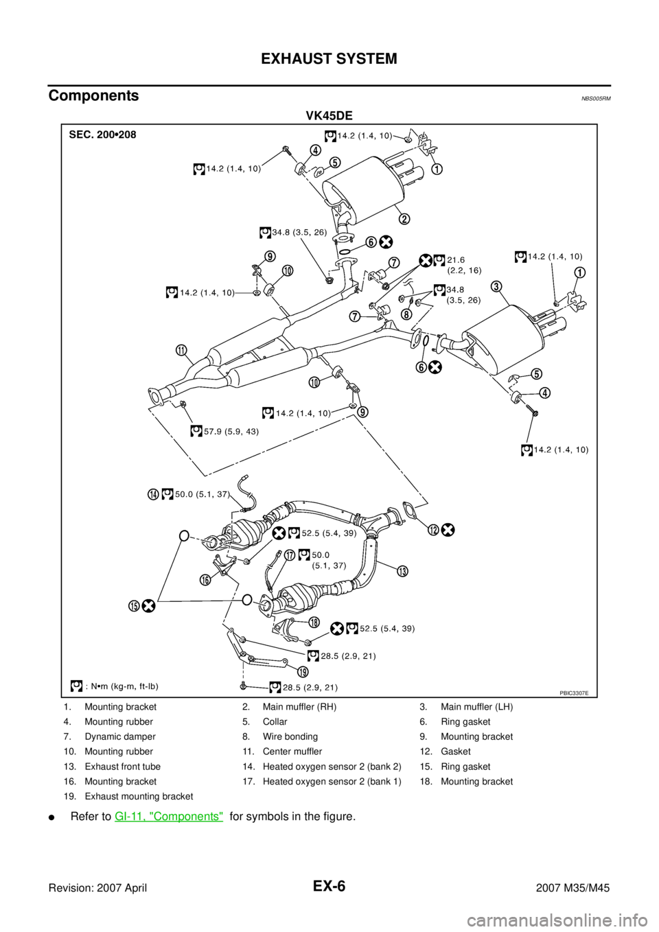
ComponentsNBS005RM
VK45DE
�Refer to GI-11, "Components" for symbols in the figure.
PBIC3307E
1. Mounting bracket 2. Main muffler (RH) 3. Main muffler (LH)
4. Mounting rubber 5. Collar 6. Ring gasket
7. Dynamic damper 8. Wire bonding 9. Mounting bracket
10. Mounting rubber 11. Center muffler 12. Gasket
13. Exhaust front tube 14. Heated oxygen sensor 2 (bank 2) 15. Ring gasket
16. Mounting bracket 17. Heated oxygen sensor 2 (bank 1) 18. Mounting bracket
19. Exhaust mounting bracket
![INFINITI M35 2007 Factory Service Manual EC-1428
[VK45DE]
REFRIGERANT PRESSURE SENSOR
Revision: 2007 April2007 M35/M45
7. CHECK REFRIGERANT PRESSURE SENSOR INPUT SIGNAL CIRCUIT FOR OPEN AND SHORT
1. Check harness continuity between ECM termi](/manual-img/42/57024/w960_57024-2956.png "INFINITI M35 2007 Factory Service Manual EC-1428
[VK45DE]
REFRIGERANT PRESSURE SENSOR
Revision: 2007 April2007 M35/M45
7. CHECK REFRIGERANT PRESSURE SENSOR INPUT SIGNAL CIRCUIT FOR OPEN AND SHORT
1. Check harness continuity between ECM termi")
![INFINITI M35 2007 Factory Service Manual SERVICE DATA AND SPECIFICATIONS (SDS)
EC-1441
[VK45DE]
C
D
E
F
G
H
I
J
K
L
MA
EC
Revision: 2007 April2007 M35/M45
Heated Oxygen Sensor 2 HeaterNBS005R3
Throttle Control MotorNBS005R4
Fuel InjectorNBS0](/manual-img/42/57024/w960_57024-2969.png "INFINITI M35 2007 Factory Service Manual SERVICE DATA AND SPECIFICATIONS (SDS)
EC-1441
[VK45DE]
C
D
E
F
G
H
I
J
K
L
MA
EC
Revision: 2007 April2007 M35/M45
Heated Oxygen Sensor 2 HeaterNBS005R3
Throttle Control MotorNBS005R4
Fuel InjectorNBS0")