Page 4427 of 4647

SRS-46
FRONT PASSENGER AIR BAG MODULE
Revision: 2007 April2007 M35/M45
FRONT PASSENGER AIR BAG MODULEPFP:K8515
Removal and InstallationNHS0009E
REMOVAL
CAUTION:
�Before servicing, turn ignition switch OFF, disconnect both battery terminal and wait at
least 3 minutes.
�Do not use air tools or electric tools for servicing.
�Always work from the side of air bag module. Do not work from the front of it.
�Always place air bag module with pad side facing upward.
�Do not use old fixing bolts after removal; replace with new bolts.
�Do not make an impact to the air bag module by dropping etc. Replace the air bag module if it has
been dropped or sustained an impact.
1. Remove the instrument panel & pad assemblies. Refer to IP-10,
"INSTRUMENT PANEL ASSEMBLY" .
NOTE:
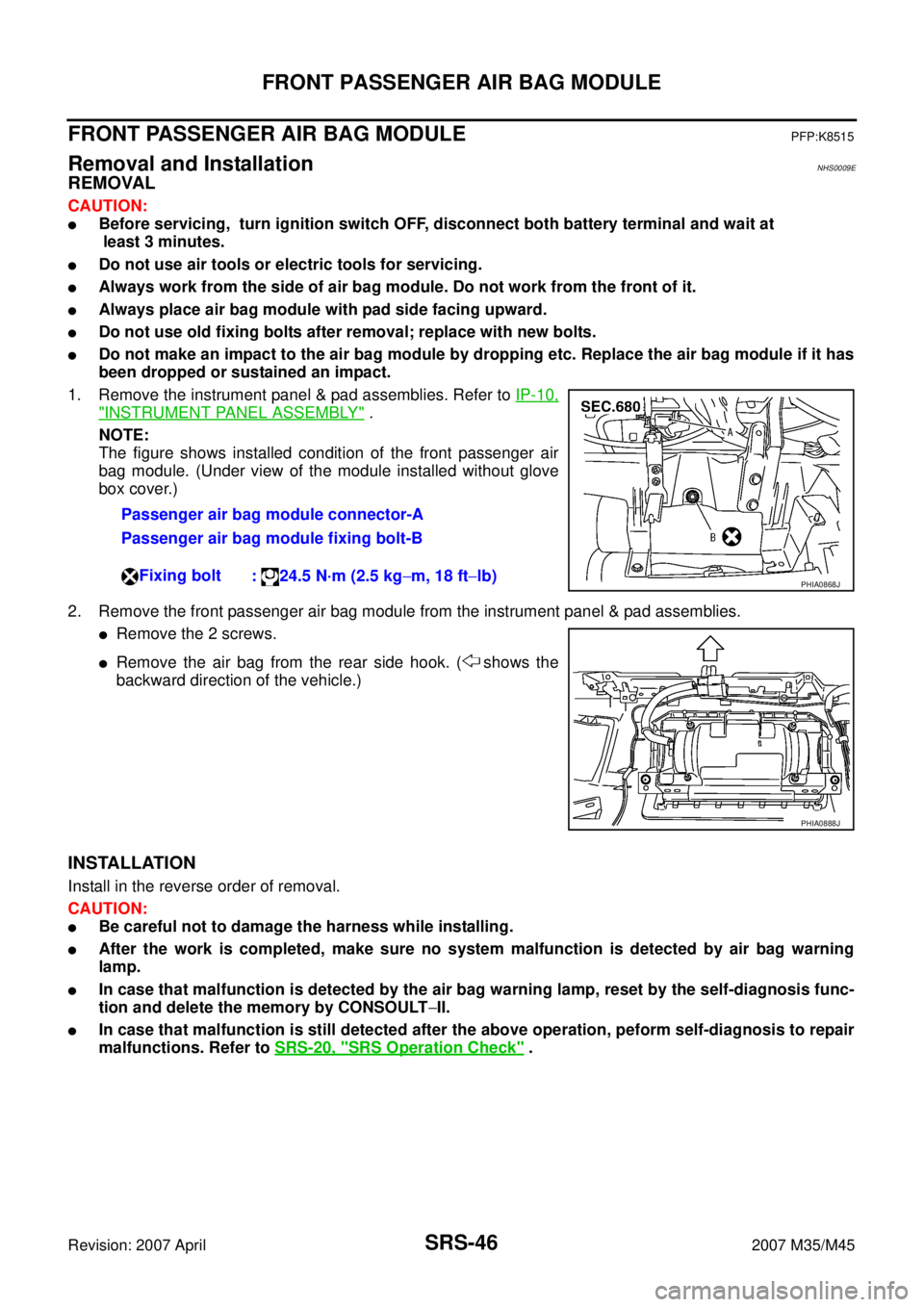
The figure shows installed condition of the front passenger air
bag module. (Under view of the module installed without glove
box cover.)
2. Remove the front passenger air bag module from the instrument panel & pad assemblies.
�Remove the 2 screws.
�Remove the air bag from the rear side hook. ( shows the
backward direction of the vehicle.)
INSTALLATION
Install in the reverse order of removal.
CAUTION:
�Be careful not to damage the harness while installing.
�After the work is completed, make sure no system malfunction is detected by air bag warning
lamp.
�In case that malfunction is detected by the air bag warning lamp, reset by the self-diagnosis func-
tion and delete the memory by CONSOULT−II.
�In case that malfunction is still detected after the above operation, peform self-diagnosis to repair
malfunctions. Refer to SRS-20, "
SRS Operation Check" . Passenger air bag module connector-A
Passenger air bag module fixing bolt-B
Fixing bolt
: 24.5 N·m (2.5 kg−m, 18 ft−lb)
PHIA0868J
PHIA0888J
Page 4433 of 4647

SRS-52
DIAGNOSIS SENSOR UNIT
Revision: 2007 April2007 M35/M45
DIAGNOSIS SENSOR UNITPFP:28556
Removal and InstallationNHS0009J
REMOVAL
CAUTION:
�Before servicing, turn ignition switch OFF, disconnect both battery terminal and wait at least 3
minutes.
�Before disconnecting the air bag sensor unit harness connector, be sure to disconnect the each
harness connector of the air bag module and pre-tensioner seatbelt to prevent air bag deployment
by static electricity and pre-tensioner seatbelt operation.
�Do not use air tools or electric tools for servicing.
�Do not use old fixing bolts after removal; replace with new bolts.
�Do not make an impact to the diagnosis sensor unit by dropping etc. Replace the diagnosis sen-
sor unit if it has been dropped or sustained an impact.
�Replace the diagnosis sensor unit of deployed SRS air bag and deployed SRS front seat belt pre-
tensioner.
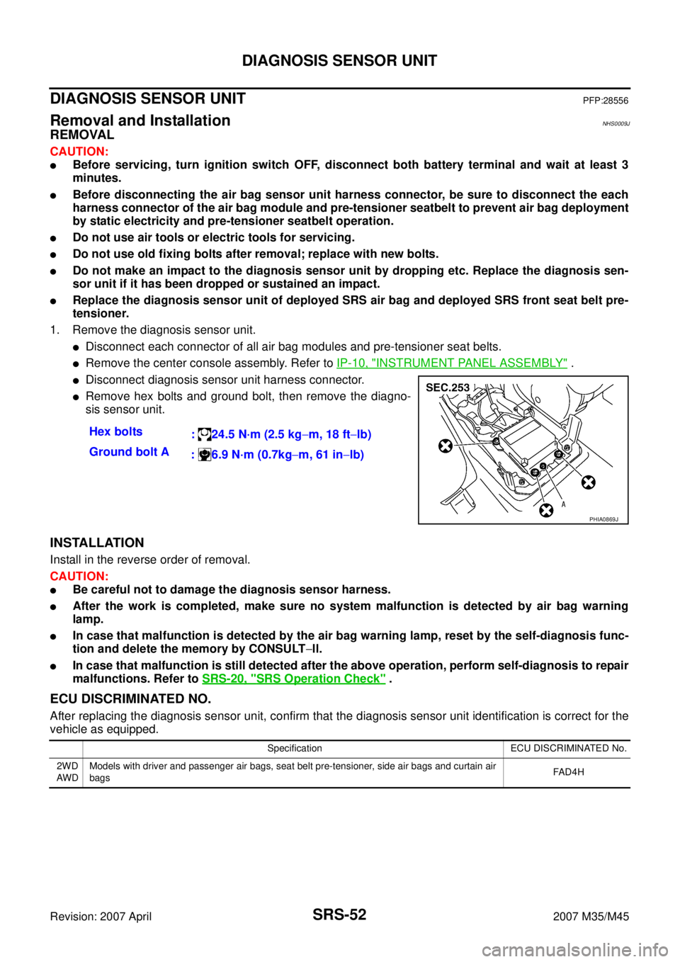
1. Remove the diagnosis sensor unit.
�Disconnect each connector of all air bag modules and pre-tensioner seat belts.
�Remove the center console assembly. Refer to IP-10, "INSTRUMENT PANEL ASSEMBLY" .
�Disconnect diagnosis sensor unit harness connector.
�Remove hex bolts and ground bolt, then remove the diagno-
sis sensor unit.
INSTALLATION
Install in the reverse order of removal.
CAUTION:
�Be careful not to damage the diagnosis sensor harness.
�After the work is completed, make sure no system malfunction is detected by air bag warning
lamp.
�In case that malfunction is detected by the air bag warning lamp, reset by the self-diagnosis func-
tion and delete the memory by CONSULT−ll.
�In case that malfunction is still detected after the above operation, perform self-diagnosis to repair
malfunctions. Refer to SRS-20, "
SRS Operation Check" .
ECU DISCRIMINATED NO.
After replacing the diagnosis sensor unit, confirm that the diagnosis sensor unit identification is correct for the
vehicle as equipped.Hex bolts
: 24.5 N·m (2.5 kg−m, 18 ft−lb)
Ground bolt A
: 6.9 N·m (0.7kg−m, 61 in−lb)
PHIA0869J
Specification ECU DISCRIMINATED No.
2WD
AW DModels with driver and passenger air bags, seat belt pre-tensioner, side air bags and curtain air
bagsFA D 4 H
Page 4436 of 4647
COLLISION DIAGNOSIS
SRS-55
C
D
E
F
G
I
J
K
L
MA
B
SRS
Revision: 2007 April2007 M35/M45
Steering wheel [same text as in current manual]
Spiral cable If the Driver airbag has deployed:
REPLACE the spiral cable.If the Driver airbag has not deployed:
[same text as in current manual]
Harness and con-
nectors1. Check connectors for poor connection, damage, and terminals for deformities.
2. Check harness for binding, chafing, cuts, or deformities.
3. If no damage is found, reinstall the harness and connectors.
4. If damaged—REPLACE damaged section of harness. Do not repair, splice or modify any SRS harness.
Instrument panel 1. Visually check instrument panel for damage.
2. If no damage is found, reinstall the instrument panel.
3. If damaged—REPLACE the instrument panel with bolts. Part SRS is activated SRS is NOT activated
Page 4589 of 4647

WT-40
REMOVAL AND INSTALLATION
Revision: 2007 April2007 M35/M45
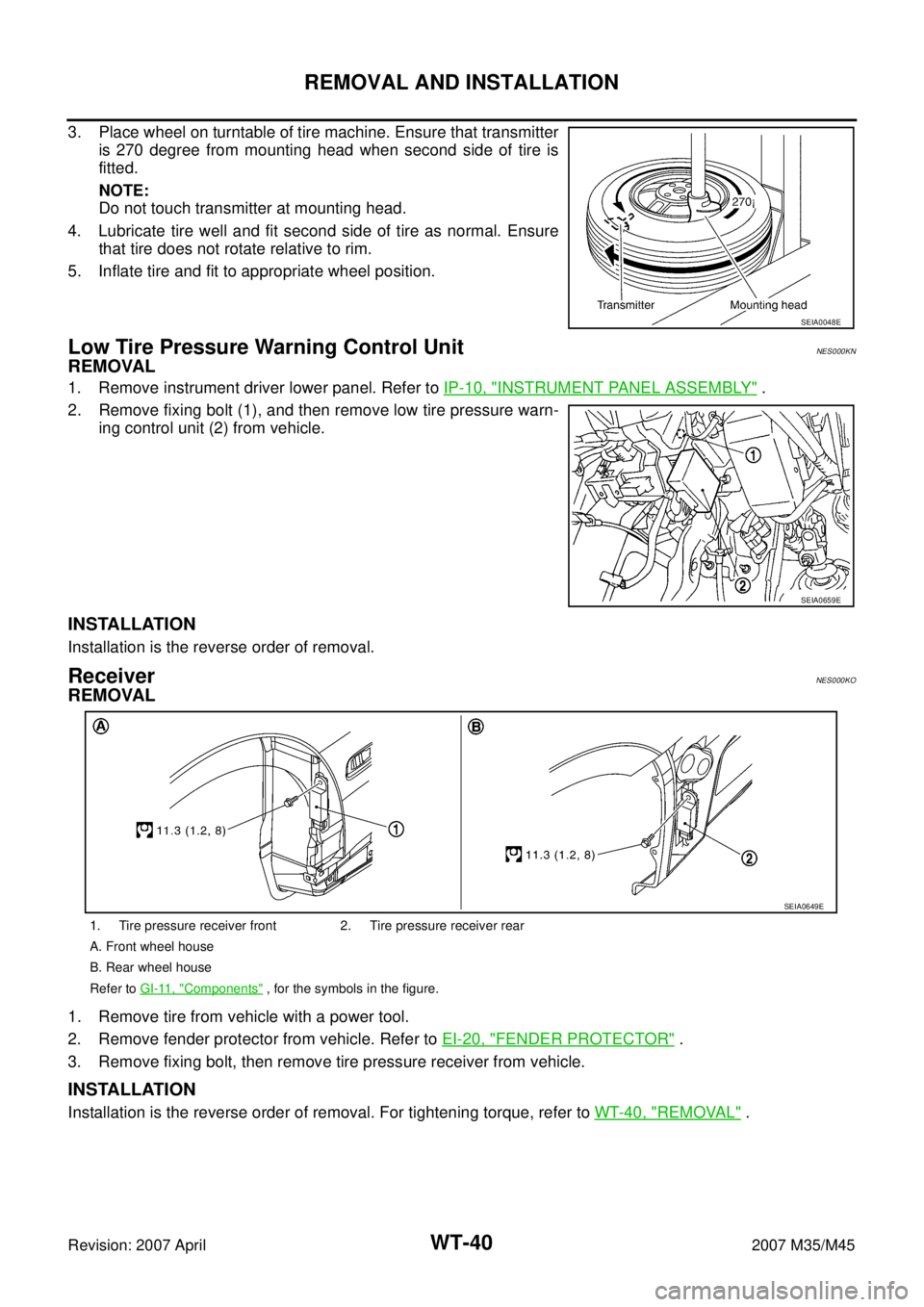
3. Place wheel on turntable of tire machine. Ensure that transmitter
is 270 degree from mounting head when second side of tire is
fitted.
NOTE:
Do not touch transmitter at mounting head.
4. Lubricate tire well and fit second side of tire as normal. Ensure
that tire does not rotate relative to rim.
5. Inflate tire and fit to appropriate wheel position.
Low Tire Pressure Warning Control UnitNES000KN
REMOVAL
1. Remove instrument driver lower panel. Refer to IP-10, "INSTRUMENT PANEL ASSEMBLY" .
2. Remove fixing bolt (1), and then remove low tire pressure warn-
ing control unit (2) from vehicle.
INSTALLATION
Installation is the reverse order of removal.
ReceiverNES000KO
REMOVAL
1. Remove tire from vehicle with a power tool.
2. Remove fender protector from vehicle. Refer to EI-20, "
FENDER PROTECTOR" .
3. Remove fixing bolt, then remove tire pressure receiver from vehicle.
INSTALLATION
Installation is the reverse order of removal. For tightening torque, refer to WT-40, "REMOVAL" .
SEIA0048E
SEIA0659E
1. Tire pressure receiver front 2. Tire pressure receiver rear
A. Front wheel house
B. Rear wheel house
Refer to GI-11, "
Components" , for the symbols in the figure.
SEIA0649E
Page 4638 of 4647
FRONT WIPER AND WASHER SYSTEM
WW-47
C
D
E
F
G
H
I
J
L
MA
B
WW
Revision: 2007 April2007 M35/M45
Inspection for Washer Nozzle NKS003X4
CHECK VALVE INSPECTION
Blow air in the injection direction, and make sure that air flows only
one way. Make sure that the reverse direction (inhale) is not possi-
ble.
Inspection of Front Wiper and Washer Switch CircuitNKS003X5
Refer to LT- 2 3 9 , "Combination Switch Inspection" .
Removal and Installation of Front Wiper and Washer SwitchNKS003X6
REMOVAL
1. Remove steering column cover. Refer to IP-10, "INSTRUMENT PANEL ASSEMBLY" .
2. Disconnect the wiper and washer switch connector.
3. Pull wiper and washer switch (1) toward the passenger door
while pressing pawls (A) in direction shown by the arrow in the
figure, and remove it from the base.
INSTALLATION
Installation is the reverse order of removal.
SKIB4256E
SKIB4257E
Page 4642 of 4647
CIGARETTE LIGHTER
WW-51
C
D
E
F
G
H
I
J
L
MA
B
WW
Revision: 2007 April2007 M35/M45
Removal and InstallationNKS003XA
REMOVAL
1. Remove A/T console finisher. Refer to IP-10, "INSTRUMENT PANEL ASSEMBLY" .
2. Remove screws (A) from reverse side cigarette lighter socket.
3. Pull out cigarette lighter (1).
4. Insert a small screwdriver or similar tool between the cigarette
lighter socket (2) and cigarette lighter ring (3). Pull out cigarette
lighter socket (2).
INSTALLATION
Note the following, and installation is the reverse order of removal.
CAUTION:
Align notches of cigarette lighter ring and cigarette lighter socket when installing.
SKIB4207E
SKIB4262E
Page 4644 of 4647

POWER SOCKET
WW-53
C
D
E
F
G
H
I
J
L
MA
B
WW
Revision: 2007 April2007 M35/M45
Removal and Installation of Center Console Box Power SocketNKS003XC
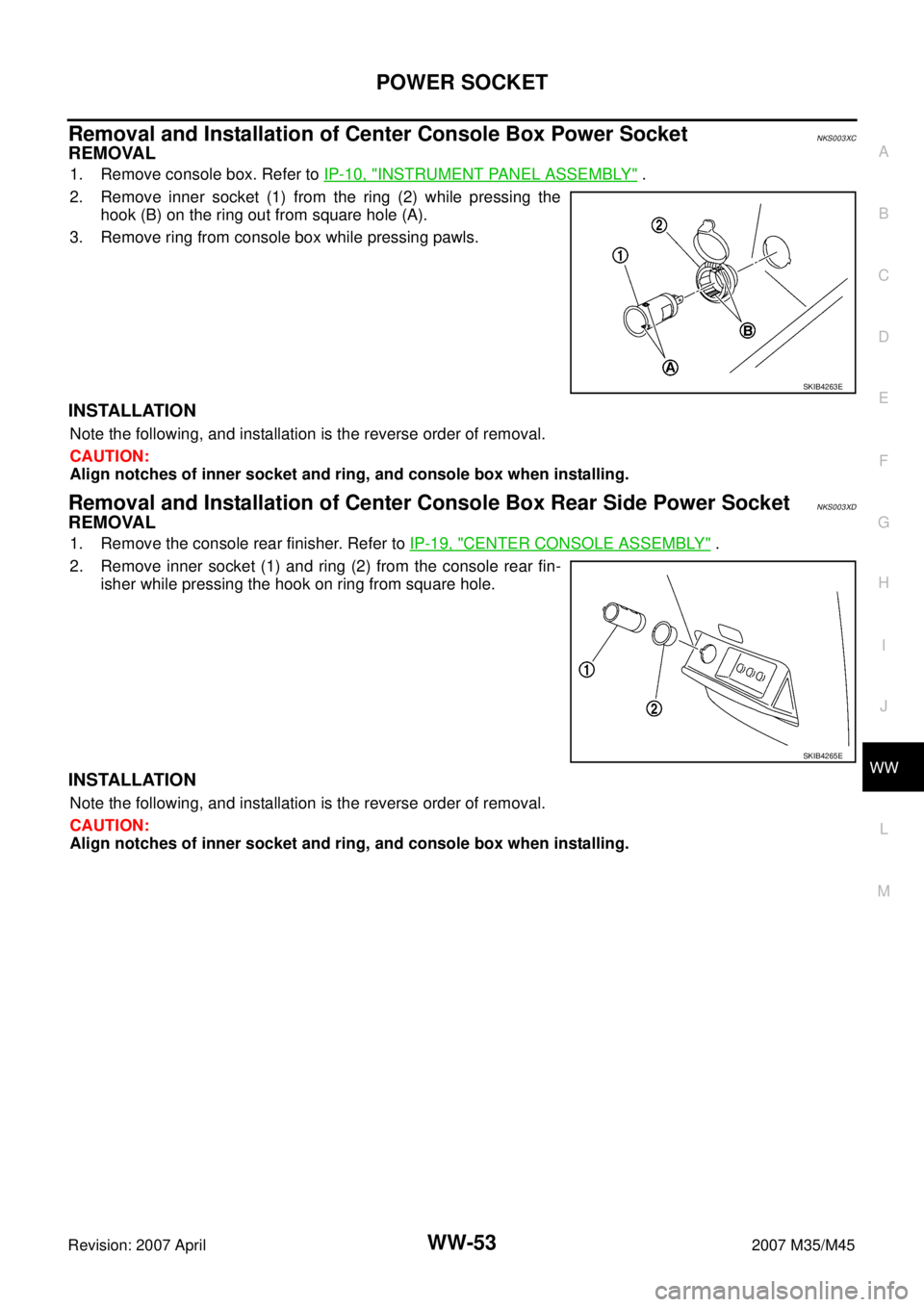
REMOVAL
1. Remove console box. Refer to IP-10, "INSTRUMENT PANEL ASSEMBLY" .
2. Remove inner socket (1) from the ring (2) while pressing the
hook (B) on the ring out from square hole (A).
3. Remove ring from console box while pressing pawls.
INSTALLATION
Note the following, and installation is the reverse order of removal.
CAUTION:
Align notches of inner socket and ring, and console box when installing.
Removal and Installation of Center Console Box Rear Side Power SocketNKS003XD
REMOVAL
1. Remove the console rear finisher. Refer to IP-19, "CENTER CONSOLE ASSEMBLY" .
2. Remove inner socket (1) and ring (2) from the console rear fin-
isher while pressing the hook on ring from square hole.
INSTALLATION
Note the following, and installation is the reverse order of removal.
CAUTION:
Align notches of inner socket and ring, and console box when installing.
SKIB4263E
SKIB4265E