Page 4351 of 4647
SE-152
HEATED SEAT
Revision: 2007 April2007 M35/M45
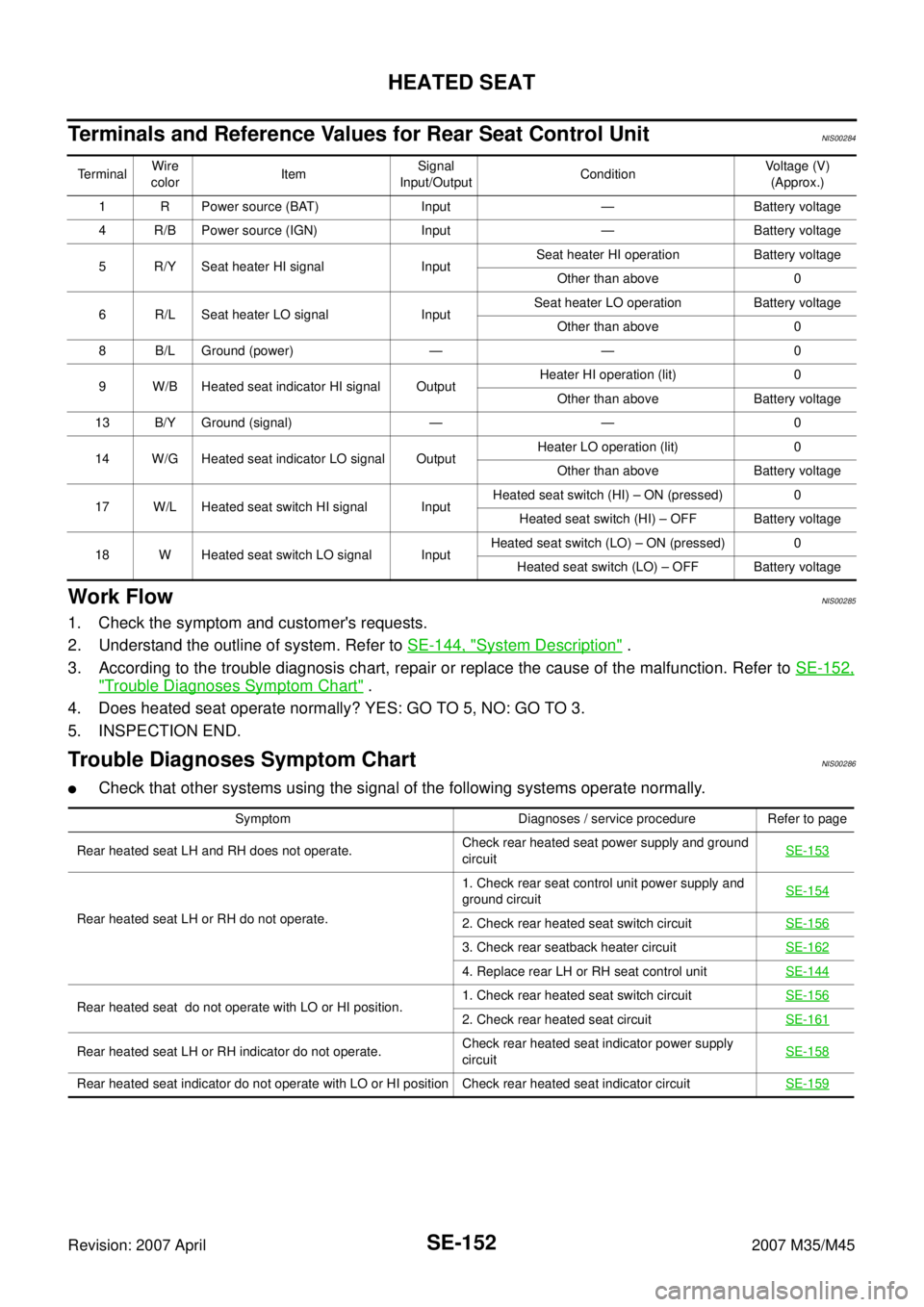
Terminals and Reference Values for Rear Seat Control UnitNIS00284
Work FlowNIS00285
1. Check the symptom and customer's requests.
2. Understand the outline of system. Refer to SE-144, "
System Description" .
3. According to the trouble diagnosis chart, repair or replace the cause of the malfunction. Refer to SE-152,
"Trouble Diagnoses Symptom Chart" .
4. Does heated seat operate normally? YES: GO TO 5, NO: GO TO 3.
5. INSPECTION END.
Trouble Diagnoses Symptom ChartNIS00286
�Check that other systems using the signal of the following systems operate normally.
TerminalWire
colorItemSignal
Input/OutputConditionVoltage (V)
(Approx.)
1 R Power source (BAT) Input — Battery voltage
4 R/B Power source (IGN) Input — Battery voltage
5 R/Y Seat heater HI signal InputSeat heater HI operation Battery voltage
Other than above 0
6 R/L Seat heater LO signal InputSeat heater LO operation Battery voltage
Other than above 0
8 B/L Ground (power) — — 0
9 W/B Heated seat indicator HI signal OutputHeater HI operation (lit) 0
Other than above Battery voltage
13 B/Y Ground (signal) — — 0
14 W/G Heated seat indicator LO signal OutputHeater LO operation (lit) 0
Other than above Battery voltage
17 W/L Heated seat switch HI signal InputHeated seat switch (HI) – ON (pressed) 0
Heated seat switch (HI) – OFF Battery voltage
18 W Heated seat switch LO signal InputHeated seat switch (LO) – ON (pressed) 0
Heated seat switch (LO) – OFF Battery voltage
Symptom Diagnoses / service procedure Refer to page
Rear heated seat LH and RH does not operate.Check rear heated seat power supply and ground
circuitSE-153
Rear heated seat LH or RH do not operate.1. Check rear seat control unit power supply and
ground circuitSE-1542. Check rear heated seat switch circuit SE-156
3. Check rear seatback heater circuit SE-162
4. Replace rear LH or RH seat control unitSE-144
Rear heated seat do not operate with LO or HI position.1. Check rear heated seat switch circuitSE-1562. Check rear heated seat circuitSE-161
Rear heated seat LH or RH indicator do not operate.Check rear heated seat indicator power supply
circuit SE-158
Rear heated seat indicator do not operate with LO or HI position Check rear heated seat indicator circuit SE-159
Page 4352 of 4647
HEATED SEAT
SE-153
C
D
E
F
G
H
J
K
L
MA
B
SE
Revision: 2007 April2007 M35/M45
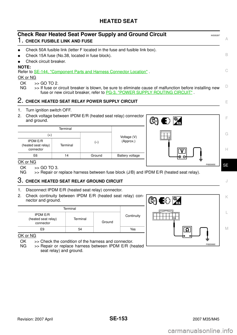
Check Rear Heated Seat Power Supply and Ground CircuitNIS00287
1. CHECK FUSIBLE LINK AND FUSE
�Check 50A fusible link (letter F located in the fuse and fusible link box).
�Check 15A fuse (No.38, located in fuse block).
�Check circuit breaker.
NOTE:
Refer to SE-144, "
Component Parts and Harness Connector Location" .
OK or NG
OK >> GO TO 2.
NG >> If fuse or circuit breaker is blown, be sure to eliminate cause of malfunction before installing new
fuse or new circuit breaker, refer to PG-3, "
POWER SUPPLY ROUTING CIRCUIT" .
2. CHECK HEATED SEAT RELAY POWER SUPPLY CIRCUIT
1. Turn ignition switch OFF.
2. Check voltage between IPDM E/R (heated seat relay) connector
and ground.
OK or NG
OK >> GO TO 3.
NG >> Repair or replace harness between fuse block (J/B) and IPDM E/R (heated seat relay).
3. CHECK HEATED SEAT RELAY GROUND CIRCUIT
1. Disconnect IPDM E/R (heated seat relay) connector.
2. Check continuity between IPDM E/R (heated seat relay) con-
nector and ground.
OK or NG
OK >> Check the condition of the harness and connector.
NG >> Repair or replace harness between IPDM E/R (heated
seat relay) and ground.
Terminal
Voltage (V)
(Approx.) (+)
(–) IPDM E/R
(heated seat relay)
connectorTerminal
E6 14 Ground Battery voltage
PIIB5995E
Terminal
Continuity IPDM E/R
(heated seat relay)
connectorTerminal
Ground
E9 54 Yes
PIIB5996E
Page 4353 of 4647
SE-154
HEATED SEAT
Revision: 2007 April2007 M35/M45
Check Rear Seat Control Unit Power Supply and Ground CircuitNIS00288
1. CHECK REAR SEAT CONTROL UNIT POWER SUPPLY CIRCUIT (BAT)
1. Turn ignition switch OFF.
2. Check voltage between rear seat control unit connector and
ground.
OK or NG
OK >> GO TO 2.
NG >> Repair or replace harness between circuit breaker and rear seat control unit.
2. CHECK REAR SEAT CONTROL UNIT POWER SUPPLY CIRCUIT (IGN)
1. Turn ignition switch ON.
2. Check voltage between rear seat control unit connector and
ground.
OK or NG
OK >> GO TO 4.
NG >> GO TO 3.
Terminal
Voltage (V)
(Approx.) (+)
(–)
Rear seat control
unit connectorTerminal
B303 (LH)
B353 (RH)1 Ground Battery voltage
PIIB5997E
Terminal
Voltage (V)
(Approx.) (+)
(–)
Rear seat control
unit connectorTerminal
B303 (LH)
B353 (RH)4 Ground Battery voltage
PIIB5998E
Page 4357 of 4647
SE-158
HEATED SEAT
Revision: 2007 April2007 M35/M45
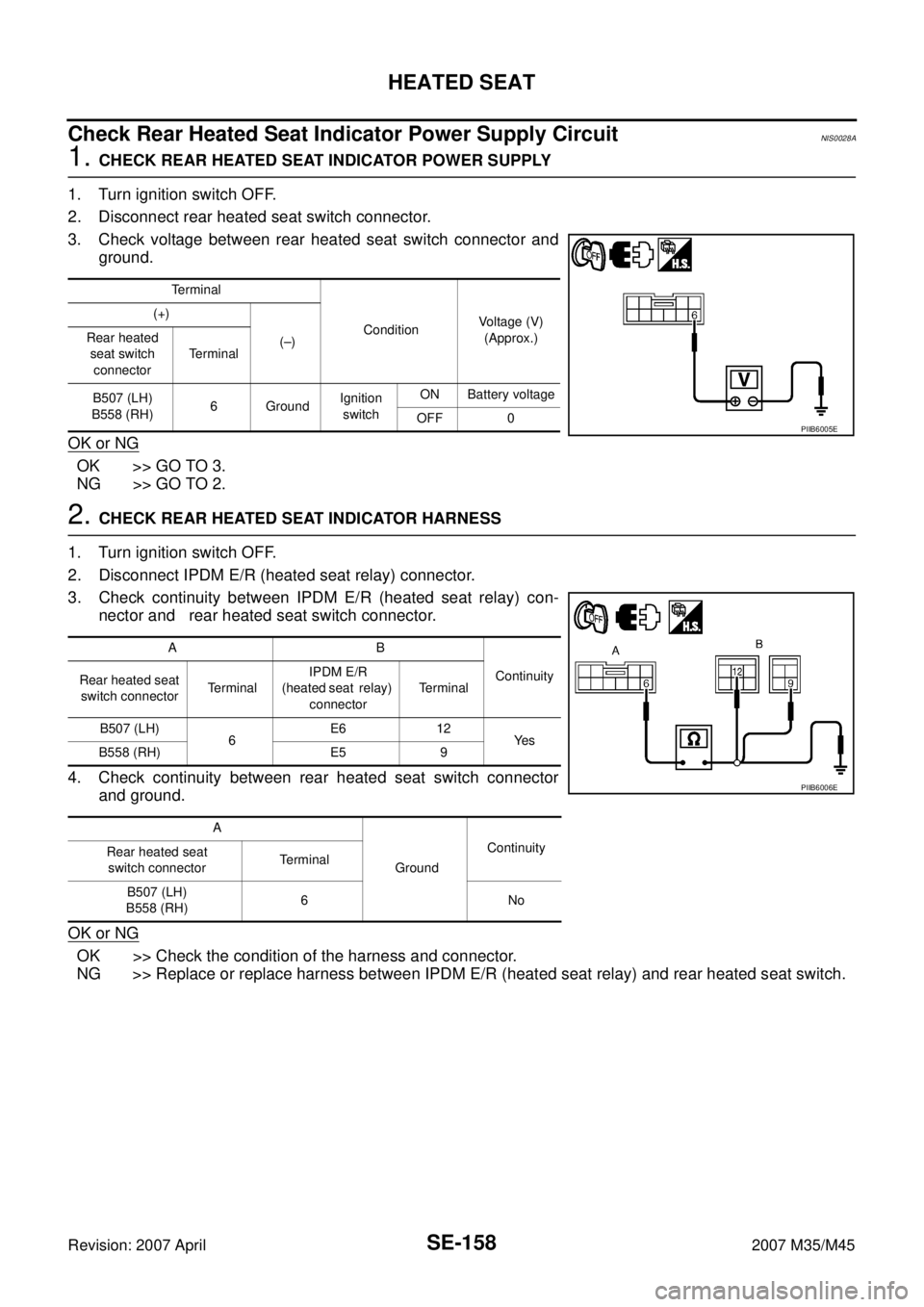
Check Rear Heated Seat Indicator Power Supply CircuitNIS0028A
1. CHECK REAR HEATED SEAT INDICATOR POWER SUPPLY
1. Turn ignition switch OFF.
2. Disconnect rear heated seat switch connector.
3. Check voltage between rear heated seat switch connector and
ground.
OK or NG
OK >> GO TO 3.
NG >> GO TO 2.
2. CHECK REAR HEATED SEAT INDICATOR HARNESS
1. Turn ignition switch OFF.
2. Disconnect IPDM E/R (heated seat relay) connector.
3. Check continuity between IPDM E/R (heated seat relay) con-
nector and rear heated seat switch connector.
4. Check continuity between rear heated seat switch connector
and ground.
OK or NG
OK >> Check the condition of the harness and connector.
NG >> Replace or replace harness between IPDM E/R (heated seat relay) and rear heated seat switch.
Terminal
ConditionVoltage (V)
(Approx.) (+)
(–) Rear heated
seat switch
connectorTerminal
B507 (LH)
B558 (RH)6GroundIgnition
switchON Battery voltage
OFF 0
PIIB6005E
AB
Continuity
Rear heated seat
switch connectorTe r m i n a lIPDM E/R
(heated seat relay)
connectorTerminal
B507 (LH)
6E6 12
Ye s
B558 (RH) E5 9
A
GroundContinuity
Rear heated seat
switch connectorTerminal
B507 (LH)
B558 (RH)6No
PIIB6006E
Page 4358 of 4647
HEATED SEAT
SE-159
C
D
E
F
G
H
J
K
L
MA
B
SE
Revision: 2007 April2007 M35/M45
3. CHECK REAR HEATED SEAT SWITCH
Check continuity rear heated seat switch connector.
OK or NG
OK >> Check the condition of the harness and connector.
NG >> Replace rear heated seat switch.
Check Rear Heated Seat Indicator CircuitNIS0028B
1. CHECK REAR SEAT CONTROL UNIT POWER SUPPLY
1. Turn ignition switch ON.
2. Check voltage between rear seat control unit connector and
ground.
OK or NG
OK >> Replace rear heated seat switch.
NG >> GO TO 2.
Rear heated seat
switch connectorTe r m i n a l
Continuity
(+) (-)
B507 (LH)
B558 (RH)4
6Yes
5
64
No
5
PIIB6007E
Te r m i n a l
ConditionVoltage (V)
(Approx.) (+)
(–) Rear seat
control unit
connectorTerminal
B304 (LH)
B354 (RH)9
GroundRear heated
seat switch HIGH 0
Other than above. Battery voltage
14Rear heated
seat switch LOW 0
Other than above. Battery voltage
PIIB6008E
Page 4360 of 4647
HEATED SEAT
SE-161
C
D
E
F
G
H
J
K
L
MA
B
SE
Revision: 2007 April2007 M35/M45
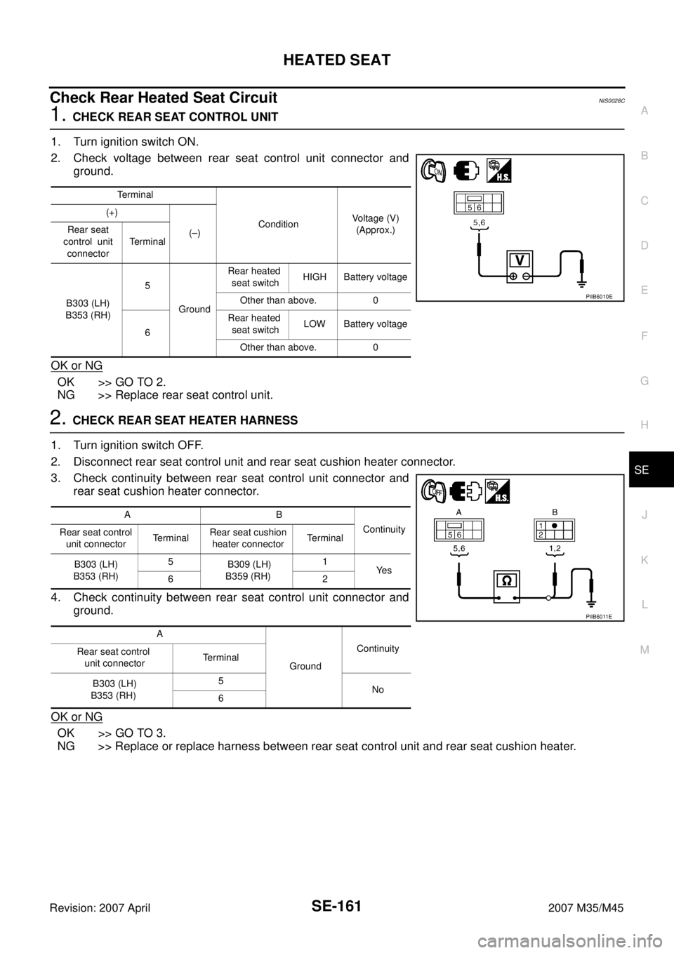
Check Rear Heated Seat CircuitNIS0028C
1. CHECK REAR SEAT CONTROL UNIT
1. Turn ignition switch ON.
2. Check voltage between rear seat control unit connector and
ground.
OK or NG
OK >> GO TO 2.
NG >> Replace rear seat control unit.
2. CHECK REAR SEAT HEATER HARNESS
1. Turn ignition switch OFF.
2. Disconnect rear seat control unit and rear seat cushion heater connector.
3. Check continuity between rear seat control unit connector and
rear seat cushion heater connector.
4. Check continuity between rear seat control unit connector and
ground.
OK or NG
OK >> GO TO 3.
NG >> Replace or replace harness between rear seat control unit and rear seat cushion heater.
Te r m i n a l
ConditionVoltage (V)
(Approx.) (+)
(–) Rear seat
control unit
connectorTe r m i n a l
B303 (LH)
B353 (RH)5
GroundRear heated
seat switchHIGH Battery voltage
Other than above. 0
6Rear heated
seat switchLOW Battery voltage
Other than above. 0
PIIB6010E
AB
Continuity
Rear seat control
unit connectorTerminalRear seat cushion
heater connectorTerminal
B303 (LH)
B353 (RH)5
B309 (LH)
B359 (RH)1
Ye s
62
A
GroundContinuity
Rear seat control
unit connectorTerminal
B303 (LH)
B353 (RH)5
No
6
PIIB6011E
Page 4361 of 4647
SE-162
HEATED SEAT
Revision: 2007 April2007 M35/M45
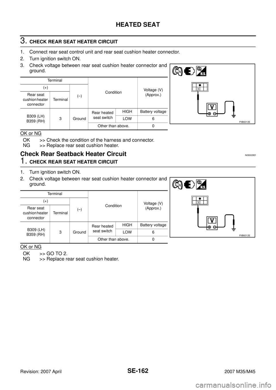
3. CHECK REAR SEAT HEATER CIRCUIT
1. Connect rear seat control unit and rear seat cushion heater connector.
2. Turn ignition switch ON.
3. Check voltage between rear seat cushion heater connector and
ground.
OK or NG
OK >> Check the condition of the harness and connector.
NG >> Replace rear seat cushion heater.
Check Rear Seatback Heater CircuitNIS0028D
1. CHECK REAR SEAT HEATER CIRCUIT
1. Turn ignition switch ON.
2. Check voltage between rear seat cushion heater connector and
ground.
OK or NG
OK >> GO TO 2.
NG >> Replace rear seat cushion heater.
Terminal
ConditionVoltage (V)
(Approx.) (+)
(–) Rear seat
cushion heater
connectorTerminal
B309 (LH)
B359 (RH)3 GroundRear heated
seat switchHIGH Battery voltage
LOW 6
Other than above. 0
PIIB6012E
Terminal
ConditionVoltage (V)
(Approx.) (+)
(–) Rear seat
cushion heater
connectorTerminal
B309 (LH)
B359 (RH)3 GroundRear heated
seat switchHIGH Battery voltage
LOW 6
Other than above. 0
PIIB6012E
Page 4367 of 4647
SE-168
FRONT SEAT
Revision: 2007 April2007 M35/M45
Removal and InstallationNIS0028G
CAUTION:
When removing and installing, use shop cloths to protect parts from damage.
REMOVAL
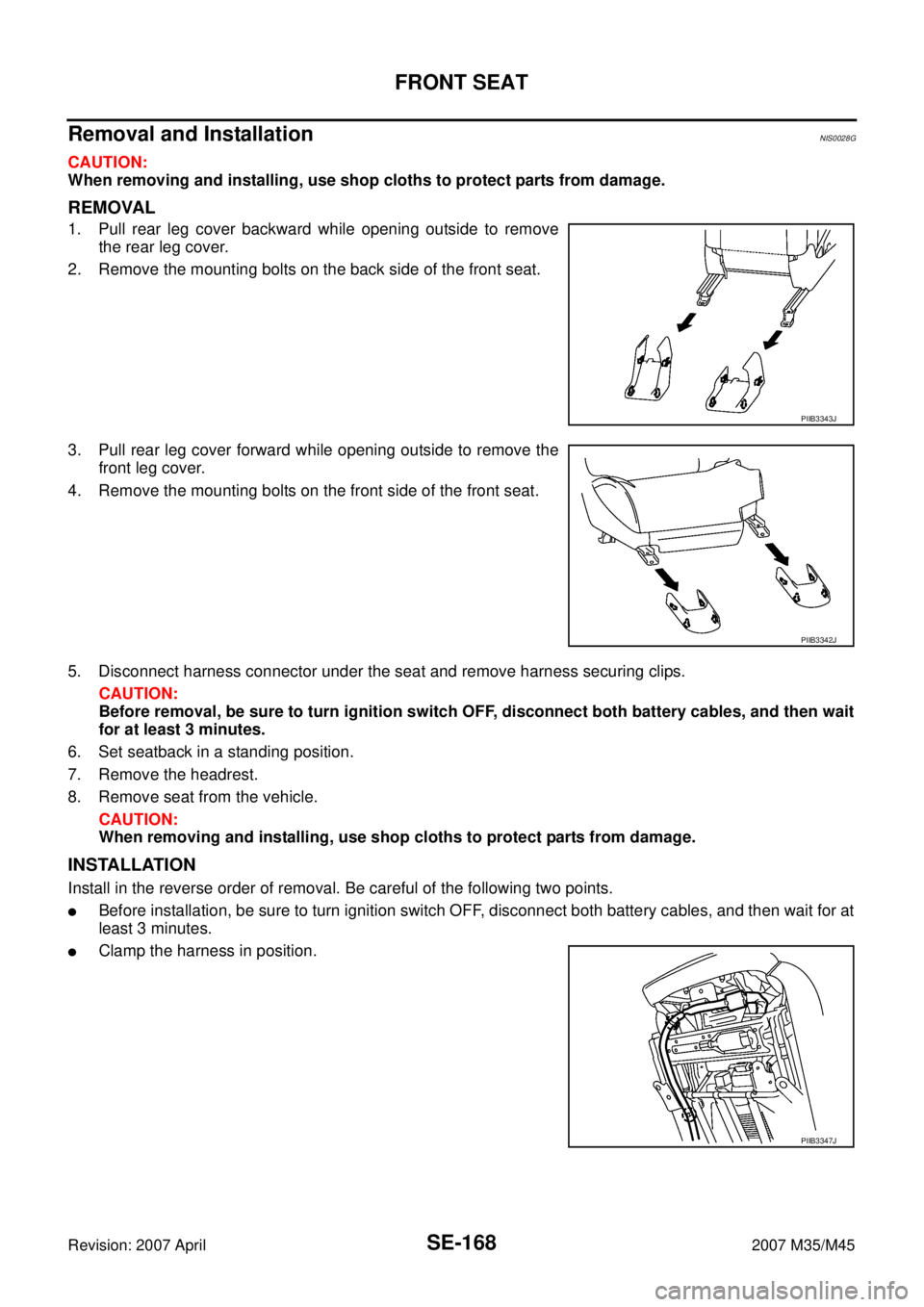
1. Pull rear leg cover backward while opening outside to remove
the rear leg cover.
2. Remove the mounting bolts on the back side of the front seat.
3. Pull rear leg cover forward while opening outside to remove the
front leg cover.
4. Remove the mounting bolts on the front side of the front seat.
5. Disconnect harness connector under the seat and remove harness securing clips.
CAUTION:
Before removal, be sure to turn ignition switch OFF, disconnect both battery cables, and then wait
for at least 3 minutes.
6. Set seatback in a standing position.
7. Remove the headrest.
8. Remove seat from the vehicle.
CAUTION:
When removing and installing, use shop cloths to protect parts from damage.
INSTALLATION
Install in the reverse order of removal. Be careful of the following two points.
�Before installation, be sure to turn ignition switch OFF, disconnect both battery cables, and then wait for at
least 3 minutes.
�Clamp the harness in position.
PIIB3343J
PIIB3342J
PIIB3347J