Page 4302 of 4647
POWER SEAT(REAR)
SE-103
C
D
E
F
G
H
J
K
L
MA
B
SE
Revision: 2007 April2007 M35/M45
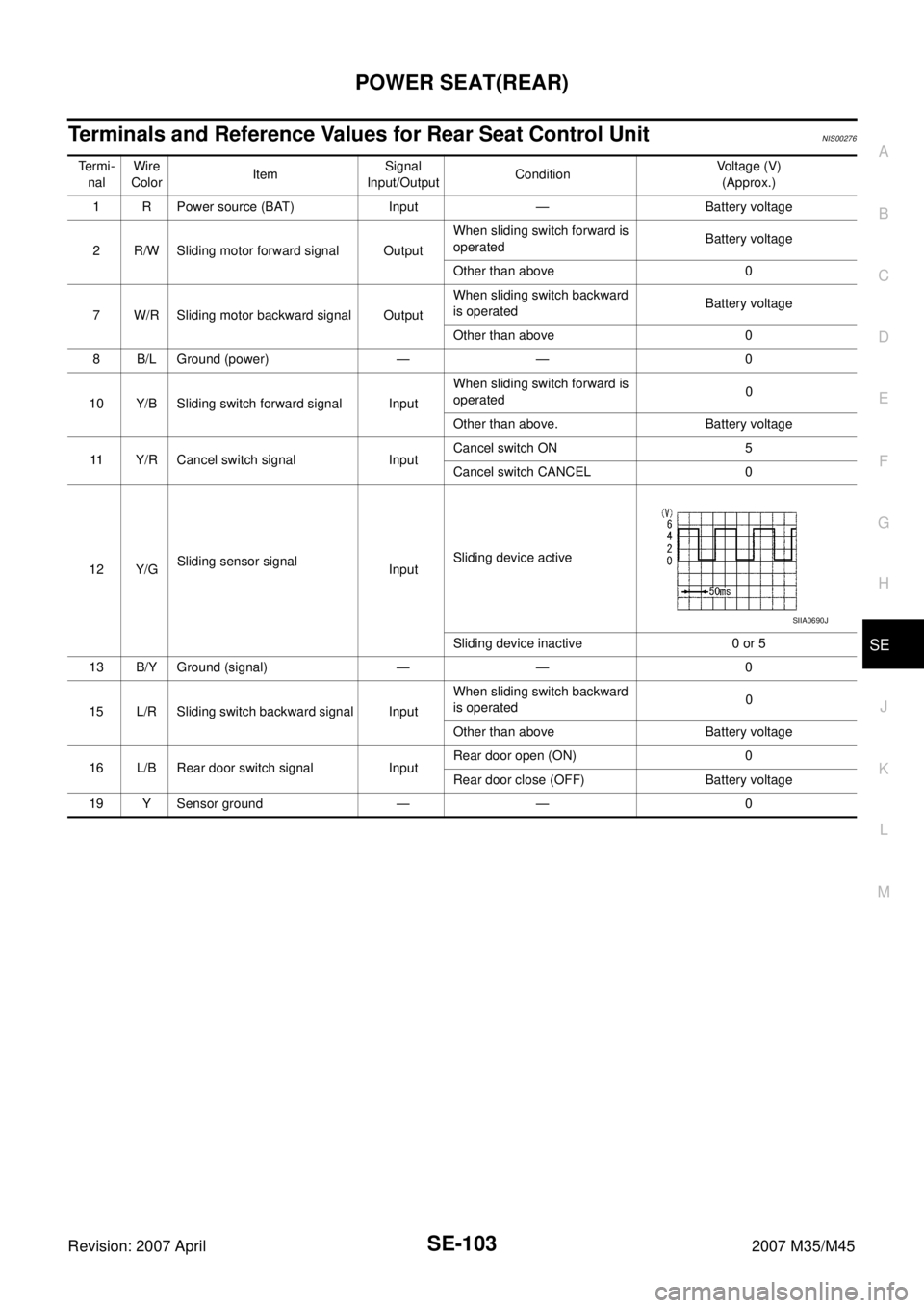
Terminals and Reference Values for Rear Seat Control Unit NIS00276
Te r m i -
nalWire
ColorItemSignal
Input/OutputConditionVoltage (V)
(Approx.)
1 R Power source (BAT) Input — Battery voltage
2 R/W Sliding motor forward signal OutputWhen sliding switch forward is
operatedBattery voltage
Other than above 0
7 W/R Sliding motor backward signal OutputWhen sliding switch backward
is operatedBattery voltage
Other than above 0
8 B/L Ground (power) — — 0
10 Y/B Sliding switch forward signal InputWhen sliding switch forward is
operated0
Other than above. Battery voltage
11 Y/R Cancel switch signal InputCancel switch ON 5
Cancel switch CANCEL 0
12 Y/GSliding sensor signal
InputSliding device active
Sliding device inactive 0 or 5
13 B/Y Ground (signal) — — 0
15 L/R Sliding switch backward signal InputWhen sliding switch backward
is operated0
Other than above Battery voltage
16 L/B Rear door switch signal InputRear door open (ON) 0
Rear door close (OFF) Battery voltage
19 Y Sensor ground — — 0
SIIA0690J
Page 4304 of 4647
POWER SEAT(REAR)
SE-105
C
D
E
F
G
H
J
K
L
MA
B
SE
Revision: 2007 April2007 M35/M45
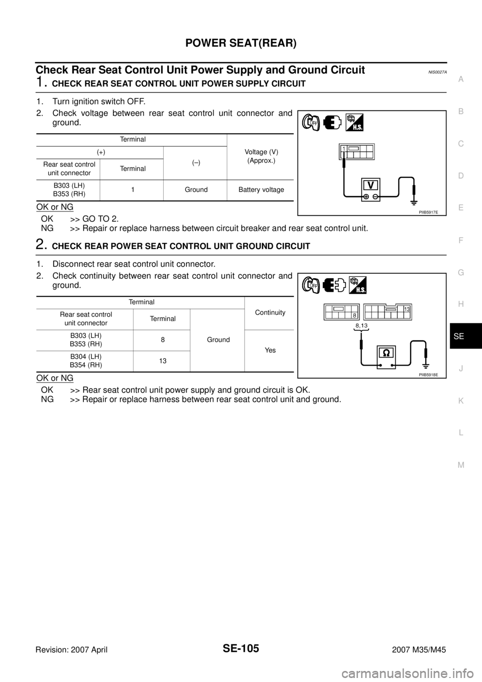
Check Rear Seat Control Unit Power Supply and Ground CircuitNIS0027A
1. CHECK REAR SEAT CONTROL UNIT POWER SUPPLY CIRCUIT
1. Turn ignition switch OFF.
2. Check voltage between rear seat control unit connector and
ground.
OK or NG
OK >> GO TO 2.
NG >> Repair or replace harness between circuit breaker and rear seat control unit.
2. CHECK REAR POWER SEAT CONTROL UNIT GROUND CIRCUIT
1. Disconnect rear seat control unit connector.
2. Check continuity between rear seat control unit connector and
ground.
OK or NG
OK >> Rear seat control unit power supply and ground circuit is OK.
NG >> Repair or replace harness between rear seat control unit and ground.
Terminal
Voltage (V)
(Approx.) (+)
(–)
Rear seat control
unit connectorTerminal
B303 (LH)
B353 (RH)1 Ground Battery voltage
PIIB5917E
Terminal
Continuity
Rear seat control
unit connectorTerminal
Ground B303 (LH)
B353 (RH)8
Ye s
B304 (LH)
B354 (RH)13
PIIB5918E
Page 4305 of 4647
SE-106
POWER SEAT(REAR)
Revision: 2007 April2007 M35/M45
Check Rear Seat Sliding Motor CircuitNIS0027B
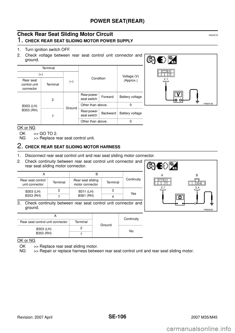
1. CHECK REAR SEAT SLIDING MOTOR POWER SUPPLY
1. Turn ignition switch OFF.
2. Check voltage between rear seat control unit connector and
ground.
OK or NG
OK >> GO TO 2.
NG >> Replace rear seat control unit.
2. CHECK REAR SEAT SLIDING MOTOR HARNESS
1. Disconnect rear seat control unit and rear seat sliding motor connector.
2. Check continuity between rear seat control unit connector and
rear seat sliding motor connector.
3. Check continuity between rear seat control unit connector and
ground.
OK or NG
OK >> Replace rear seat sliding motor.
NG >> Repair or replace harness between rear seat control unit and rear seat sliding motor.
Terminal
ConditionVoltage (V)
(Approx.) (+)
(–) Rear seat
control unit
connectorTerminal
B303 (LH)
B353 (RH)2
GroundRear power
seat switch Forward Battery voltage
Other than above. 0
7Rear power
seat switch Backward Battery voltage
Other than above. 0
PIIB5919E
AB
Continuity
Rear seat control
unit connectorTe r m i n a lRear seat sliding
motor connectorTerminal
B303 (LH)
B353 (RH)2
B311 (LH)
B361 (RH)3
Ye s
74
A
GroundContinuity
Rear seat control unit connector Terminal
B303 (LH)
B353 (RH)2
No
7
PIIB5920E
Page 4306 of 4647
POWER SEAT(REAR)
SE-107
C
D
E
F
G
H
J
K
L
MA
B
SE
Revision: 2007 April2007 M35/M45
Check Rear Power Seat Switch CircuitNIS0027C
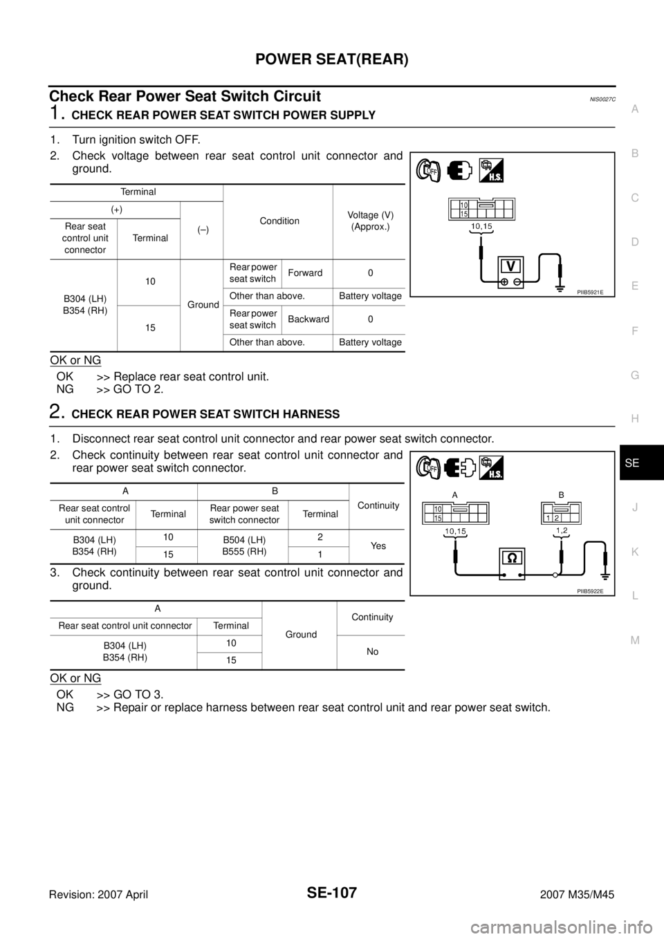
1. CHECK REAR POWER SEAT SWITCH POWER SUPPLY
1. Turn ignition switch OFF.
2. Check voltage between rear seat control unit connector and
ground.
OK or NG
OK >> Replace rear seat control unit.
NG >> GO TO 2.
2. CHECK REAR POWER SEAT SWITCH HARNESS
1. Disconnect rear seat control unit connector and rear power seat switch connector.
2. Check continuity between rear seat control unit connector and
rear power seat switch connector.
3. Check continuity between rear seat control unit connector and
ground.
OK or NG
OK >> GO TO 3.
NG >> Repair or replace harness between rear seat control unit and rear power seat switch.
Terminal
ConditionVoltage (V)
(Approx.) (+)
(–) Rear seat
control unit
connectorTerminal
B304 (LH)
B354 (RH)10
GroundRear power
seat switch Forward 0
Other than above. Battery voltage
15Rear power
seat switch Backward 0
Other than above. Battery voltage
PIIB5921E
AB
Continuity
Rear seat control
unit connectorTerminalRear power seat
switch connectorTerminal
B304 (LH)
B354 (RH)10
B504 (LH)
B555 (RH)2
Ye s
15 1
A
GroundContinuity
Rear seat control unit connector Terminal
B304 (LH)
B354 (RH)10
No
15
PIIB5922E
Page 4307 of 4647
SE-108
POWER SEAT(REAR)
Revision: 2007 April2007 M35/M45
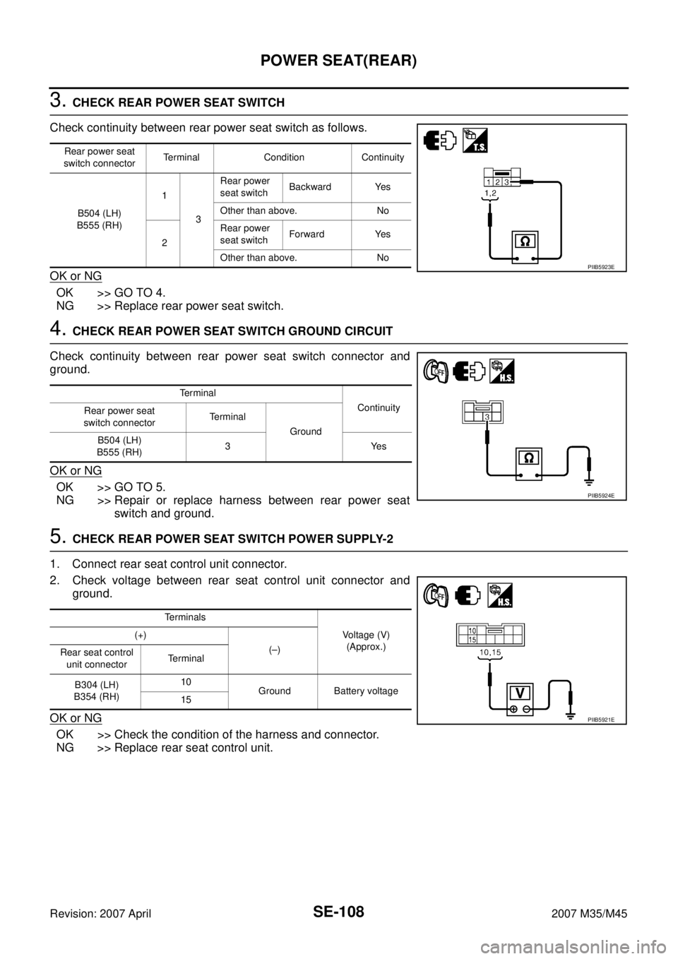
3. CHECK REAR POWER SEAT SWITCH
Check continuity between rear power seat switch as follows.
OK or NG
OK >> GO TO 4.
NG >> Replace rear power seat switch.
4. CHECK REAR POWER SEAT SWITCH GROUND CIRCUIT
Check continuity between rear power seat switch connector and
ground.
OK or NG
OK >> GO TO 5.
NG >> Repair or replace harness between rear power seat
switch and ground.
5. CHECK REAR POWER SEAT SWITCH POWER SUPPLY-2
1. Connect rear seat control unit connector.
2. Check voltage between rear seat control unit connector and
ground.
OK or NG
OK >> Check the condition of the harness and connector.
NG >> Replace rear seat control unit.
Rear power seat
switch connectorTerminal Condition Continuity
B504 (LH)
B555 (RH)1
3Rear power
seat switch Backward Yes
Other than above. No
2Rear power
seat switch Forward Yes
Other than above. No
PIIB5923E
Te r m i n a l
Continuity
Rear power seat
switch connectorTerminal
Ground
B504 (LH)
B555 (RH)3Yes
PIIB5924E
Terminals
Voltage (V)
(Approx.) (+)
(–)
Rear seat control
unit connectorTerminal
B304 (LH)
B354 (RH)10
Ground Battery voltage
15
PIIB5921E
Page 4310 of 4647
POWER SEAT(REAR)
SE-111
C
D
E
F
G
H
J
K
L
MA
B
SE
Revision: 2007 April2007 M35/M45
Check Rear Door Switch CircuitNIS0027F
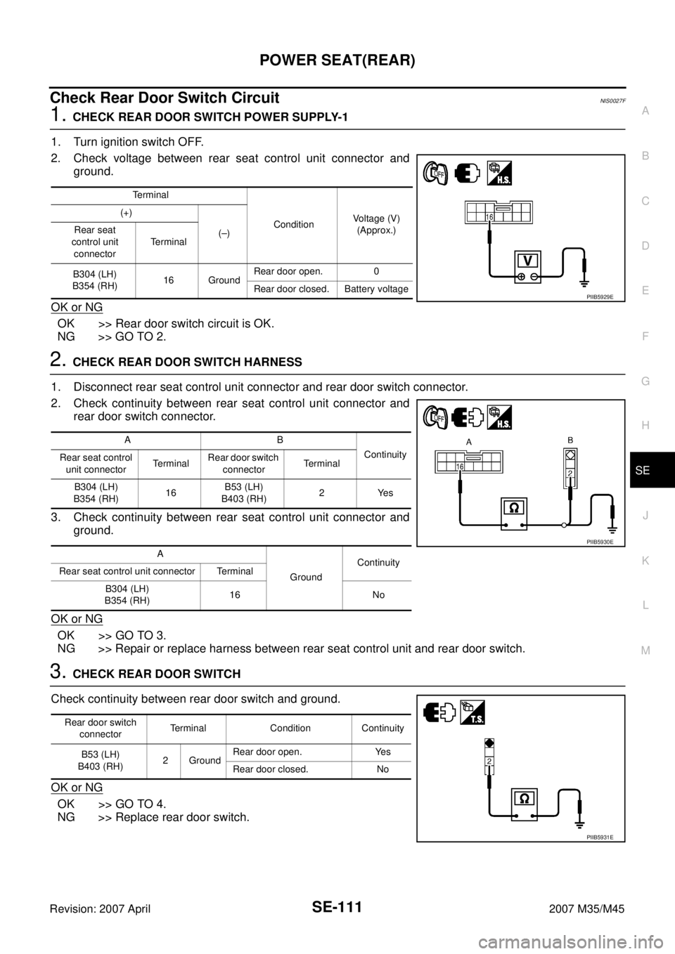
1. CHECK REAR DOOR SWITCH POWER SUPPLY-1
1. Turn ignition switch OFF.
2. Check voltage between rear seat control unit connector and
ground.
OK or NG
OK >> Rear door switch circuit is OK.
NG >> GO TO 2.
2. CHECK REAR DOOR SWITCH HARNESS
1. Disconnect rear seat control unit connector and rear door switch connector.
2. Check continuity between rear seat control unit connector and
rear door switch connector.
3. Check continuity between rear seat control unit connector and
ground.
OK or NG
OK >> GO TO 3.
NG >> Repair or replace harness between rear seat control unit and rear door switch.
3. CHECK REAR DOOR SWITCH
Check continuity between rear door switch and ground.
OK or NG
OK >> GO TO 4.
NG >> Replace rear door switch.
Terminal
ConditionVoltage (V)
(Approx.) (+)
(–) Rear seat
control unit
connectorTe r m i n a l
B304 (LH)
B354 (RH)16 GroundRear door open. 0
Rear door closed. Battery voltage
PIIB5929E
AB
Continuity
Rear seat control
unit connectorTerminalRear door switch
connectorTerminal
B304 (LH)
B354 (RH)16B53 (LH)
B403 (RH)2 Yes
A
GroundContinuity
Rear seat control unit connector Terminal
B304 (LH)
B354 (RH)16 No
PIIB5930E
Rear door switch
connectorTerminal Condition Continuity
B53 (LH)
B403 (RH)2 GroundRear door open. Yes
Rear door closed. No
PIIB5931E
Page 4311 of 4647
SE-112
POWER SEAT(REAR)
Revision: 2007 April2007 M35/M45
4. CHECK REAR DOOR SWITCH POWER SUPPLY-2
1. Connect rear seat control unit connector.
2. Check voltage between rear seat control unit connector and
ground.
OK or NG
OK >> Check the condition of the harness and connector.
NG >> Replace rear seat control unit.
Check Rear Seat Sliding Sensor CircuitNIS0027G
1. CHECK REAR SEAT SLIDING SENSOR POWER SUPPLY
1. Turn ignition switch OFF.
2. Check signal between rear seat control unit connector and
ground with oscilloscope.
OK or NG
OK >> Check the condition of the harness and connector.
NG >> GO TO 2.
Terminals
Voltage (V)
(Approx.) (+)
(–)
Rear seat control
unit connectorTerminal
B304 (LH)
B354 (RH)16 Ground Battery voltage
PIIB5929E
Terminal
ConditionSignal
(Reference valve) (+)
(–) Rear seat
control unit
connectorTerminal
B304 (LH)
B354 (RH)12 GroundSliding
device
active
PIIB5932E
SIIA0690J
Page 4323 of 4647

SE-124
CLIMATE CONTROLLED SEAT
Revision: 2007 April2007 M35/M45
Terminal and Reference Value for Climate Controlled Seat Control UnitNIS0027L
Te r -
minalWire
ColorItemSignal
Input/
OutputConditionVoltage (V)
(Approx)
2 R/Y Ignition switch power supply Input Ignition switch ON or START Battery voltage
3 B Ground — — 0
4 R/Y Ignition switch power supply Input Ignition switch ON or START Battery voltage
5G/RSeat cushion thermal electric
device power supply (HEAT)InputIgnition switch
ON or STARTClimate controlled
seat switch selectHEAT or
COOL0 – Battery
voltage
OFF 0
6G/BSeat cushion thermal electric
device power supply (COOL)InputIgnition switch
ON or STARTClimate controlled
seat switch select COOL or
HEAT 0 – Battery
voltage
OFF 0
7 B/R Blower motor ground — — 0
8 LG/R HEAT switch indicator signal OutputIgnition switch
ON or STARTClimate controlled
seat switch select HEAT Battery voltage
OFF 0
9 LG/B COOL switch indicator signal OutputIgnition switch
ON or STARTClimate controlled
seat switch select COOL Battery voltage
OFF 0
10 Y/R HEAT switch signal InputIgnition switch
ON or STARTClimate controlled
seat switch select HI HEAT 2.6 – 3.5
MID HEAT 1.6 – 2.5
LO HEAT 0.5 – 1.5
OFF 0
11 B / RClimate controlled seat switch
power supplyInput Ignition switch ON or START Battery voltage
14 V/W Blower motor power supply Input Ignition switch ON or START Battery voltage
15 W/RSeatback thermal electric device
power supply (HEAT) InputIgnition switch
ON or STARTClimate controlled
seat switch select HEAT or
COOL0 – Battery
voltage
OFF 0
16 W/BSeatback thermal electric device
power supply (COOL) InputIgnition switch
ON or STARTClimate controlled
seat switch select COOL or
HEAT 0 – Battery
voltage
OFF 0
17 R/B Blower motor speed control signal InputIgnition switch
ON or STARTClimate controlled
seat switch select HEAT or
COOL4.5 – 8.0
OFF 0
18 V Blower motor tachometer signal OutputIgnition switch
ON or STARTClimate controlled
seat switch select HEAT or
COOL4.5 – 8.0
OFF Battery voltage
20 Y/G COOL switch signal InputIgnition switch
ON or STARTClimate controlled
seat switch select HI COOL 2.6 – 3.5
MID COOL 1.6 – 2.5
LO COOL 0.5 – 1.5
OFF 0
21 GR/LSeat cushion thermal electric
device sensor ground— Ignition switch ON 0
22 GR/RSeat cushion thermal electric
device sensor signalInputBlower motor operated 0.5 – 4
Ignition switch OFF 0