Page 4205 of 4647

SE-6
SQUEAK AND RATTLE TROUBLE DIAGNOSES
Revision: 2007 April2007 M35/M45
DUPLICATE THE NOISE AND TEST DRIVE
If possible, drive the vehicle with the customer until the noise is duplicated. Note any additional information on
the Diagnostic Worksheet regarding the conditions or location of the noise. This information can be used to
duplicate the same conditions when you confirm the repair.
If the noise can be duplicated easily during the test drive, to help identify the source of the noise, try to dupli-
cate the noise with the vehicle stopped by doing one or all of the following:
1) Close a door.
2) Tap or push/pull around the area where the noise appears to be coming from.
3) Rev the engine.
4) Use a floor jack to recreate vehicle “twist”.
5) At idle, apply engine load (electrical load, half-clutch on M/T models, drive position on A/T models).
6) Raise the vehicle on a hoist and hit a tire with a rubber hammer.
�Drive the vehicle and attempt to duplicate the conditions the customer states exist when the noise occurs.
�If it is difficult to duplicate the noise, drive the vehicle slowly on an undulating or rough road to stress the
vehicle body.
CHECK RELATED SERVICE BULLETINS
After verifying the customer concern or symptom, check ASIST for Technical Service Bulletins (TSBs) related
to that concern or symptom.
If a TSB relates to the symptom, follow the procedure to repair the noise.
LOCATE THE NOISE AND IDENTIFY THE ROOT CAUSE
1. Narrow down the noise to a general area. To help pinpoint the source of the noise, use a listening tool
(Chassis Ear: J-39570, Engine Ear and mechanics stethoscope).
2. Narrow down the noise to a more specific area and identify the cause of the noise by:
�removing the components in the area that you suspect the noise is coming from.
Do not use too much force when removing clips and fasteners, otherwise clips and fastener can be broken
or lost during the repair, resulting in the creation of new noise.
�tapping or pushing/pulling the component that you suspect is causing the noise.
Do not tap or push/pull the component with excessive force, otherwise the noise will be eliminated only
temporarily.
�feeling for a vibration with your hand by touching the component(s) that you suspect is (are) causing the
noise.
�placing a piece of paper between components that you suspect are causing the noise.
�looking for loose components and contact marks.
Refer to SE-7, "
Generic Squeak and Rattle Troubleshooting" .
REPAIR THE CAUSE
�If the cause is a loose component, tighten the component securely.
�If the cause is insufficient clearance between components:
–separate components by repositioning or loosening and retightening the component, if possible.
–insulate components with a suitable insulator such as urethane pads, foam blocks, felt cloth tape or ure-
thane tape. A Nissan Squeak and Rattle Kit (J-43980) is available through your authorized Nissan Parts
Department.
CAUTION:
Do not use excessive force as many components are constructed of plastic and may be damaged.
NOTE:
Always check with the Parts Department for the latest parts information.
The following materials are contained in the Nissan Squeak and Rattle Kit (J-43980). Each item can be
ordered separately as needed.
URETHANE PADS [1.5 mm (0.059 in) thick]
Insulates connectors, harness, etc.
76268-9E005: 100×135 mm (3.94×5.31 in)/76884-71L01: 60×85 mm (2.36×3.35 in)/76884-
71L02: 15×25 mm (0.59×0.98 in)
INSULATOR (Foam blocks)
Insulates components from contact. Can be used to fill space behind a panel.
73982-9E000: 45 mm (1.77 in) thick, 50×50 mm (1.97×1.97 in)/73982-
50Y00: 10 mm (0.39 in) thick, 50×50 mm (1.97×1.97 in)
Page 4367 of 4647

SE-168
FRONT SEAT
Revision: 2007 April2007 M35/M45
Removal and InstallationNIS0028G
CAUTION:
When removing and installing, use shop cloths to protect parts from damage.
REMOVAL
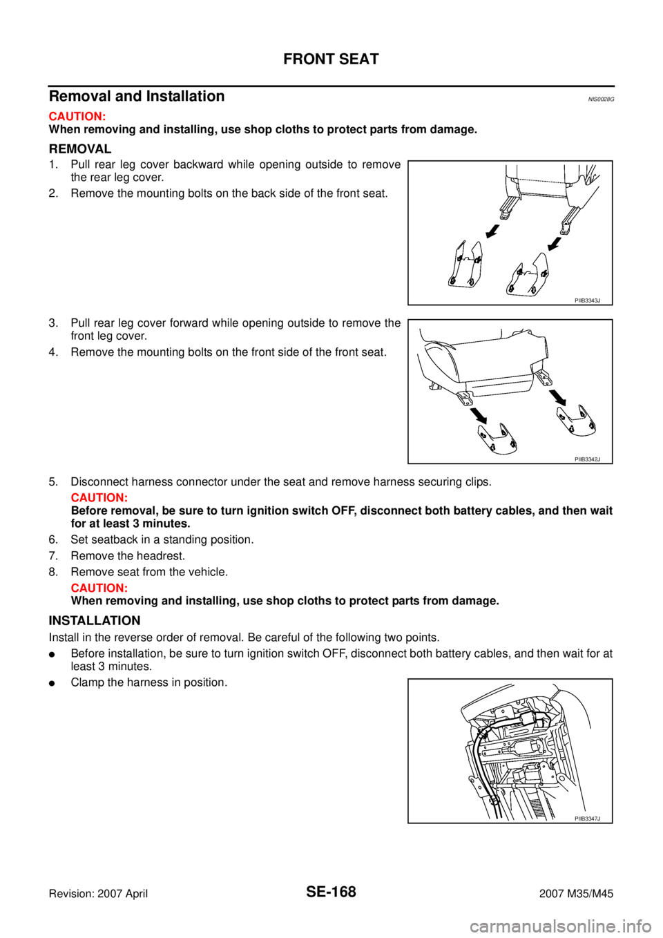
1. Pull rear leg cover backward while opening outside to remove
the rear leg cover.
2. Remove the mounting bolts on the back side of the front seat.
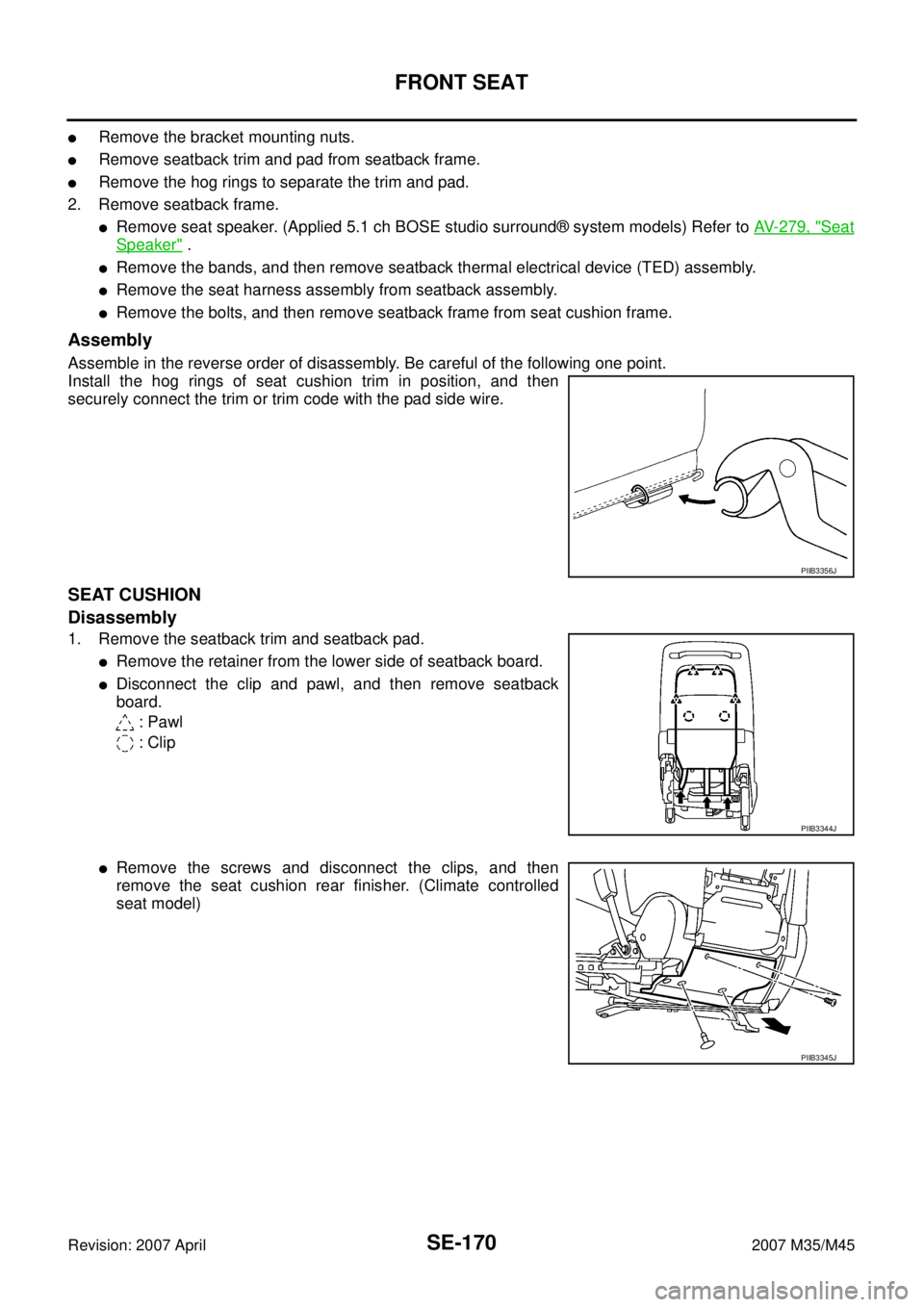
3. Pull rear leg cover forward while opening outside to remove the
front leg cover.
4. Remove the mounting bolts on the front side of the front seat.
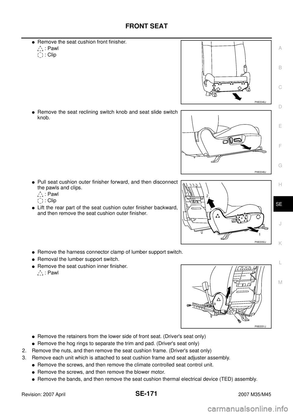
5. Disconnect harness connector under the seat and remove harness securing clips.
CAUTION:
Before removal, be sure to turn ignition switch OFF, disconnect both battery cables, and then wait
for at least 3 minutes.
6. Set seatback in a standing position.
7. Remove the headrest.
8. Remove seat from the vehicle.
CAUTION:
When removing and installing, use shop cloths to protect parts from damage.
INSTALLATION
Install in the reverse order of removal. Be careful of the following two points.
�Before installation, be sure to turn ignition switch OFF, disconnect both battery cables, and then wait for at
least 3 minutes.
�Clamp the harness in position.
PIIB3343J
PIIB3342J
PIIB3347J
Page 4368 of 4647
FRONT SEAT
SE-169
C
D
E
F
G
H
J
K
L
MA
B
SE
Revision: 2007 April2007 M35/M45
Disassembly and AssemblyNIS0028H
SEATBACK
Disassembly
1. Remove seatback trim and seatback pad.
NOTE:
Seatback trim and seatback pad can be removed without removing seatback assembly from seat body.
�Remove the retainer from the lower side of seatback board.
�Disconnect the clips and pawls, and then remove the seatback
board.
: Pawl
: Clip
�Remove the seatback hinge mounting bolts.
�Remove the retainer on the back side of the seatback.
�Remove the seat speaker grills. (Applied 5.1 ch BOSE studio surround® system models.) Refer to AV-
279, "Seat Speaker" .
�Remove the headrest holder.
CAUTION:
Before installing headrest holder, check its orientation
(front/rear and right/left).
�Disconnect the clip, and then remove the reclining device cover.
�Remove the screws, and then remove the seatback upper fin-
isher.
PIIB3344J
PIIB3353J
PIIB4084J
PIIB3355J
Page 4369 of 4647

SE-170
FRONT SEAT
Revision: 2007 April2007 M35/M45
�Remove the bracket mounting nuts.
�Remove seatback trim and pad from seatback frame.
�Remove the hog rings to separate the trim and pad.
2. Remove seatback frame.
�Remove seat speaker. (Applied 5.1 ch BOSE studio surround® system models) Refer to AV- 2 7 9 , "Seat
Speaker" .
�Remove the bands, and then remove seatback thermal electrical device (TED) assembly.
�Remove the seat harness assembly from seatback assembly.
�Remove the bolts, and then remove seatback frame from seat cushion frame.
Assembly
Assemble in the reverse order of disassembly. Be careful of the following one point.
Install the hog rings of seat cushion trim in position, and then
securely connect the trim or trim code with the pad side wire.
SEAT CUSHION
Disassembly
1. Remove the seatback trim and seatback pad.
�Remove the retainer from the lower side of seatback board.
�Disconnect the clip and pawl, and then remove seatback
board.
: Pawl
: Clip
�Remove the screws and disconnect the clips, and then
remove the seat cushion rear finisher. (Climate controlled
seat model)
PIIB3356J
PIIB3344J
PIIB3345J
Page 4370 of 4647

FRONT SEAT
SE-171
C
D
E
F
G
H
J
K
L
MA
B
SE
Revision: 2007 April2007 M35/M45
�Remove the seat cushion front finisher.
: Pawl
: Clip
�Remove the seat reclining switch knob and seat slide switch
knob.
�Pull seat cushion outer finisher forward, and then disconnect
the pawls and clips.
: Pawl
: Clip
�Lift the rear part of the seat cushion outer finisher backward,
and then remove the seat cushion outer finisher.
�Remove the harness connector clamp of lumber support switch.
�Removal the lumber support switch.
�Remove the seat cushion inner finisher.
: Pawl
�Remove the retainers from the lower side of front seat. (Driver's seat only)
�Remove the hog rings to separate the trim and pad. (Driver's seat only)
2. Remove the nuts, and then remove the seat cushion frame. (Driver's seat only)
3. Remove each unit which is attached to seat cushion frame and seat adjuster assembly.
�Remove the screws, and then remove the climate controlled seat control unit.
�Remove the screws, and then remove the blower motor.
�Remove the bands, and then remove the seat cushion thermal electrical device (TED) assembly.
PIIB3346J
PIIB3348J
PIIB3350J
PIIB3351J
Page 4635 of 4647

WW-44
FRONT WIPER AND WASHER SYSTEM
Revision: 2007 April2007 M35/M45
Removal and Installation of Front Wiper Drive AssemblyNKS003WZ
REMOVAL
1. Operate front wiper motor, and stop at the auto stop position.
2. Remove wiper arms. Refer to WW-43, "
REMOVAL" .
3. Remove cowl top cover. Refer to EI-18, "
COWL TOP" .
4. Disconnect wiper motor connector and remove connector clips.
5. Remove front wiper drive assembly mounting bolts (A), and
remove front wiper drive assembly (1) from the vehicle.
INSTALLATION
1. Install front wiper drive assembly to the vehicle.
2. Connect wiper motor connector. Turn wiper switch ON to operate wiper motor, then turn wiper switch OFF
(auto stop).
3. Install connector clips to the wiper frame, and install cowl top cover. Refer to EI-18, "
COWL TOP" .
4. Attach wiper arms. Refer to WW-43, "
INSTALLATION" .
5. Adjustment of wiper arm stop location.
6. Install arm caps.
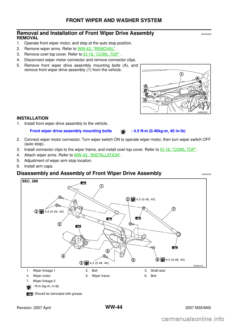
Disassembly and Assembly of Front Wiper Drive AssemblyNKS003X0
SKIB4222E
Front wiper drive assembly mounting bolts : 4.5 N·m (0.46kg-m, 40 in-lb)
1. Wiper linkage 1 2. Bolt 3. Shaft seal
4. Wiper motor 5. Wiper frame 6. Bolt
7. Wiper linkage 2
: N·m (kg-m, in-lb)
: Should be lubricated with grease.
SKIB4231E