Page 4228 of 4366

TF-24
TROUBLE DIAGNOSIS
Revision: 2006 July 2007 FX35/FX45
DATA MONITOR MODE
Operation Procedure
1. Perform “CONSULT-II Start Procedure”. Refer to GI-38, "CONSULT-II Start Procedure" .
2. Touch “DATA MONITOR”.
3. Select from “SELECT MONITOR ITEM”, screen of data monitor mode is displayed. NOTE:
When malfunction is detected, CONSULT-II performs REAL-TIME DIAGNOSIS.
Also, any malfunction detected while in this mode will be displayed at real time.
Display Item List
× : Standard –: Not applicable
Monitored item (Unit) Monitor item selection
Remarks
ECU INPUT
SIGNALS MAIN
SIGNALS SELECTION
FROM MENU
FR RH SENSOR
(km/h) or (mph) ××× Wheel speed calculated by front wheel sensor RH
signal is displayed.
FR LH SENSOR
(km/h) or (mph) ××× Wheel speed calculated by front wheel sensor LH
signal is displayed.
RR RH SENSOR
(km/h) or (mph) ×××
Wheel speed calculated by rear wheel sensor RH
signal is displayed.
RR LH SENSOR
(km/h) or (mph) ××× Wheel speed calculated by rear wheel sensor LH
signal is displayed.
BATTERY VOLT
(V) ––
×Power supply voltage for AWD control unit
THRTL POS SEN
(%) ––
×Throttle opening status is displayed.
ETS SOLENOID
(A) ––
×Monitored value of current at AWD solenoid
STOP LAMP SW
(ON/OFF) ––
× Stop lamp switch signal status via CAN communica-
tion line is displayed.
ENG SPEED SIG
(RUN/STOP) ––
×Engine status is displayed.
ETS ACTUATOR
(ON/OFF) ––
× Operating condition of AWD actuator relay (inte-
grated in AWD control unit) is displayed.
4WD WARN LAMP
(ON/OFF) ––
×Control status of AWD warning lamp is displayed.
4WD MODE SW
(AUTO) ––
×AWD lock switch is not equipped, but displayed.
4WD MODE MON
(AUTO) ––
×Control status of AWD is displayed.
DIS-TIRE MONI
(mm) ––
×Improper size tire installed condition is displayed.
P BRAKE SW
(ON/OFF) ––
× Parking switch signal status via CAN communica-
tion line is displayed.
Voltage
(V) ––
× The value measured by the voltage probe is dis-
played.
Page 4230 of 4366

TF-26
TROUBLE DIAGNOSIS FOR SYSTEM
Revision: 2006 July 2007 FX35/FX45
TROUBLE DIAGNOSIS FOR SYSTEMPFP:00000
Power Supply Circuit for AWD Control UnitNDS000A6
CONSULT-II REFERENCE VALUE IN DATA MONITOR MODE
Data are reference value.
DIAGNOSTIC PROCEDURE
1. CHECK POWER SUPPLY
1. Turn ignition switch “OFF”.
2. Disconnect AWD control unit harness connector.
3. Turn ignition switch “ON”. (Do not start engine.)
4. Check voltage between AWD control unit harness connector ter- minals and ground.
5. Turn ignition switch “OFF”.
6. Check voltage between AWD control unit harness connector ter- minals and ground.
OK or NG
OK >> GO TO 2.
NG >> Check the following. If any items are damaged, repair or replace damaged parts.
�10A fuse [No. 12 or 21, located in the fuse block (J/B)]
�Harness for short or open between battery and AWD control unit harness connector terminal 9
�Harness for short or open between ignition switch and AWD control unit harness connector ter-
minal 7
�Ignition switch. Refer to PG-3, "POWER SUPPLY ROUTING CIRCUIT" .
Monitored item [Unit] Condition Display value (Approx.)
BATTERY VOLT [V] Ignition switch: ON Battery voltage
Connector Terminal Voltage (Approx.)
M92 7 - Ground
Battery voltage
9 - Ground
SDIA2319E
Connector Terminal Voltage (Approx.)
M92 7 - Ground 0V
9 - Ground Battery voltage
SDIA2320E
Page 4233 of 4366

TROUBLE DIAGNOSIS FOR SYSTEM TF-29
C E F
G H
I
J
K L
M A
B
TF
Revision: 2006 July 2007 FX35/FX45
1. CHECK AWD SOLENOID SIGNAL
With CONSULT-II
1. Start engine.
2. Select “DATA MONITOR” mode for “ALL MODE AWD/4WD” with CONSULT-II.
3. Read out the value of “ETS SOLENOID”.
*: The values are changed by throttle opening and engine speed.
OK or NG
OK >> GO TO 6.
NG >> GO TO 2.
2. CHECK POWER SUPPLY
1. Turn ignition switch “OFF”.
2. Disconnect AWD control unit harness connector.
3. Turn ignition switch “ON”. (Do not start engine.)
4. Check voltage between AWD control unit harness connector ter- minal 9 and ground.
OK or NG
OK >> GO TO 3.
NG >> Check the following. If any items are damaged, repair or replace damaged parts.
�10A fuse [No. 21, located in the fuse block (J/B)]
�Harness for short or open between battery and AWD
control unit harness connector terminal 9
3. CHECK AWD SOLENOID CIRCUIT
1. Turn ignition switch “OFF”.
2. Disconnect AWD control unit harness connector.
3. Check resistance between AWD control unit harness connector terminals 1 and 2.
OK or NG
OK >> GO TO 6.
NG >> GO TO 4.
Condition Display value
Engine running At idle speed Approx. 0.000A
When depressing accelerator
pedal Approx. 0.000 - 2.400A*
SDIA1885E
Connector Terminal Voltage (Approx.)
M92 9 - Ground Battery voltage
SDIA1884E
Connector Terminal Resistance (Approx.)M92 1 - 2 (Ground) 2.45 Ω
SDIA1928E
Page 4238 of 4366

TF-34
TROUBLE DIAGNOSIS FOR SYMPTOMS
Revision: 2006 July 2007 FX35/FX45
2. CHECK AWD CONTROL UNIT POWER SUPPLY CIRCUIT
1. Turn ignition switch “OFF”.
2. Disconnect AWD control unit harness connector.
3. Turn ignition switch “ON”. (Do not start engine.)
4. Check voltage between AWD control unit harness connector ter- minals and ground.
5. Turn ignition switch “OFF”.
6. Check voltage between AWD control unit harness connector ter- minals and ground.
OK or NG
OK >> GO TO 3.
NG >> Check the following. If any items are damaged, repair or
replace damaged parts.
�10A fuse [No. 12 or 21, located in the fuse block (J/B)]
�Harness for short or open between battery and AWD control unit harness connector terminal 9
�Harness for short or open between ignition switch and AWD control unit harness connector ter-
minal 7
�Ignition switch. Refer to PG-3, "POWER SUPPLY ROUTING CIRCUIT" .
3. CHECK AWD CONTROL UNIT GROUND CIRCUIT
1. Turn ignition switch “OFF”.
2. Disconnect AWD control unit harness connector.
3. Check continuity between AWD control unit harness connector M92 terminals 10, 11 and ground.
Also check harness for short to ground and short to power.
OK or NG
OK >> GO TO 4.
NG >> Repair open circuit or short to ground or short to power in harness or connectors.
Connector Terminal Voltage (Approx.)
M92 7 - Ground
Battery voltage
9 - Ground
SDIA2319E
Connector Terminal Voltage (Approx.)
M92 7 - Ground 0V
9 - Ground Battery voltage
SDIA2320E
Continuity should exist.
SDIA1883E
Page 4245 of 4366
REAR OIL SEAL TF-41
C E F
G H
I
J
K L
M A
B
TF
Revision: 2006 July 2007 FX35/FX45
REAR OIL SEALPFP:33140
Removal and InstallationNDS000AL
REMOVAL
1. Remove the rear propeller shaft. Refer to PR-7, "REAR PROPELLER SHAFT" .
2. Remove self-lock nut of companion flange using the flange wrench.
3. Put matching mark on the end of the mainshaft. The mark should be in line with the mark on the companion flange.
CAUTION:
For matching mark, use paint. Do not damage mainshaft.
4. Remove the companion flange using a puller. CAUTION:
Be careful not to damage the companion flange.
5. Remove the rear oil seal using a puller. CAUTION:
Be careful not to damage the rear case.
SDIA2454E
SDIA2378E
SDIA1785E
Tool number : KV381054S0 (J-34286)
SDIA1786E
Page 4246 of 4366
TF-42
REAR OIL SEAL
Revision: 2006 July 2007 FX35/FX45
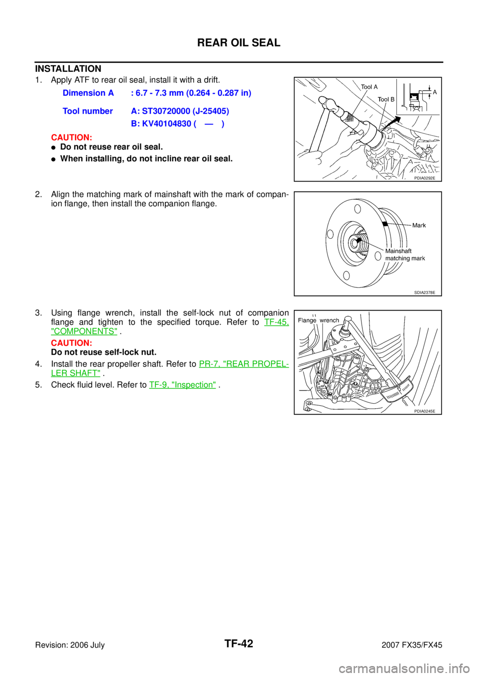
INSTALLATION
1. Apply ATF to rear oil seal, install it with a drift.
CAUTION:
�Do not reuse rear oil seal.
�When installing, do not incline rear oil seal.
2. Align the matching mark of mainshaft with the mark of compan- ion flange, then install the companion flange.
3. Using flange wrench, install the self-lock nut of companion flange and tighten to the specified torque. Refer to TF-45,
"COMPONENTS" .
CAUTION:
Do not reuse self-lock nut.
4. Install the rear propeller shaft. Refer to PR-7, "
REAR PROPEL-
LER SHAFT" .
5. Check fluid level. Refer to TF-9, "
Inspection" .
Dimension A : 6.7 - 7.3 mm (0.264 - 0.287 in)
Tool number A: ST30720000 (J-25405) B: KV40104830 ( — )
PDIA0292E
SDIA2378E
PDIA0245E
Page 4249 of 4366
TRANSFER ASSEMBLY TF-45
C E F
G H
I
J
K L
M A
B
TF
Revision: 2006 July 2007 FX35/FX45
Disassembly and AssemblyNDS000AO
COMPONENTS
1. Drive chain 2. Front drive shaft rear bearing 3. Front drive shaft
4. Front drive shaft front bearing 5. Sprocket 6. Mainshaft
7. Needle bearing 8. Snap ring 9. Mainshaft bearing
10. Front case 11. Front oil seal 12. Mainshaft oil seal
13. Oil cover 14. Temperature sensor 15. Electric controlled coupling
16. Spacer 17. Snap ring 18. O-ring
19. Oil gutter 20. Drain plug 21. Baffle plate
22. Rear bearing 23. Snap ring 24. Spacer
25. Rear oil seal 26. Companion flange 27. Self-lock nut
28. Breather tube 29. Rear case 30. Harness bracket
31. Retainer 32. Filler plug 33. Gasket
PDIA0244E
Page 4250 of 4366
TF-46
TRANSFER ASSEMBLY
Revision: 2006 July 2007 FX35/FX45
DISASSEMBLY
Front Case and Rear Case
1. Remove drain plug and filler plug.
2. Remove mainshaft oil seal from front case, using a flat-bladed screwdriver.
CAUTION:
Be careful not to damage the front case and mainshaft.
3. Remove front oil seal from front case, using a flat-bladed screw- driver.
CAUTION:
Be careful not to damage the front case and front drive
shaft.
4. Remove self-lock nut.
5. Put a matching mark on the end of mainshaft. The mark should be in line with the mark on the companion flange.
CAUTION:
For matching mark, use paint. Do not damage mainshaft.
6. Remove companion flange, using a puller. CAUTION:
Be careful not to damage the companion flange.
PDIA0253E
PDIA0255E
SDIA2378E
PDIA0258E