Page 4136 of 4366
SE-98
FRONT SEAT
Revision: 2006 July 2007 FX35/FX45
1. Headrest 2. Headrest holder (free) 3. Headrest holder (locked)
4. Seatback pad 5. Seatback trim 6. Seat cushion inner finisher
7. Screw 8. Seat cushion trim 9. Seat cushion pad
PIIB8524E
Page 4143 of 4366
, and pull the se")
REAR SEAT SE-105
C
D E
F
G H
J
K L
M A
B
SE
Revision: 2006 July 2007 FX35/FX45
REMOVAL
1. Pull the lock at the front bottom of the seat cushion forward (1
for each side), and pull the seat cushion upward to release the
wire from the plastic hook, then pull the seat cushion forward to
remove.
2. Remove the seatback mounting nuts.
3. Remove the seatback mounting bolt and nut. Remove the remote control wire.
INSTALLATION
Install in the reverse order of removal.
NOTE:
After rear wheel house finisher assembly is remove the seatback is installed. Refer to EI-45, "
Removal and
Installation" .
1. Headrest (side) 2. Headrest holder (free) 3. Headrest holder (locked)
4. Seatback trim (RH) 5. Seatback pad (RH) 6. Seatback frame (RH)
7. Nut 8. Seat hinge cover (RH) 9. Screw
10. Reclining lever (RH) 11. Reclining device outer cover (RH) 12. Reclining device inner cover (RH)
13. Bolt 14. Seatback garnish (RH) 15. Trunk net hook
16. Clip (C101) 17. Headrest (center) 18. Seatback trim (LH)
19. Seatback pad (LH) 20. Seatback frame (LH) 21. Seatback garnish (LH)
22. Armrest bracket cover 23. Armrest bracket 24. Armrest
25. Reclining device inner cover (LH) 26. Reclining device outer cover (LH) 27. Reclining lever (LH)
28. Seat hinge cover (LH) 29. Seat cushion trim 30. Seat cushion pad
31. Cup holder bracket 32. Cup holder
PIIA6034E
PIIA6035E
PIIA6036E
Page 4185 of 4366

TROUBLE DIAGNOSIS SRS-39
C
D E
F
G
I
J
K L
M A
B
SRS
Revision: 2006 July 2007 FX35/FX45
Trouble Diagnosis: “AIR BAG” Warning Lamp Does Not Turn OFFNHS0007J
DIAGNOSTIC PROCEDURE 7
1. CHECK THE DEPLOYMENT OF AIR BAG MODULE
Is air bag module deployed?
YES or NO
YES >> Refer to SRS-55, "COLLISION DIAGNOSIS" .
NO >> GO TO 2.
2. CHECK THE AIR BAG FUSE
Check 10A fuse [No. 13, located in fuse block (J/B)].
Refer to PG-3, "
POWER SUPPLY ROUTING CIRCUIT" .
OK or NG
OK >> GO TO 4.
NG >> GO TO 3.
3. CHECK AIR BAG FUSE AGAIN
Replace “AIR BAG” fuse and turn ignition switch ON.
Does the
“AIR BAG” fuse blow again?
YES >> Repair or replace main harness.
NO >> INSPECTION END
4. CHECK DIAGNOSIS SENSOR UNIT
Connect CONSULT-II and touch “START”.
Is “AIR BAG” displayed on CONSULT-II?
YES or NO
YES >> GO TO 5.
NO >> Visually check the wiring harness connection of diagno- sis sensor unit. If the harness connection check result is
OK, replace diagnosis sensor unit.
5. CHECK HARNESS CONNECTION
Is harness connection between warning lamp and diagnosis sensor unit OK?
OK or NG
OK >> Replace diagnosis sensor unit.
NG >> Connect “AIR BAG” warning lamp and diagnosis sensor unit connector properly. If “AIR BAG” warning lamp still does not go off, replace harness.
BCIA0030E
Page 4186 of 4366
SRS-40
TROUBLE DIAGNOSIS
Revision: 2006 July 2007 FX35/FX45
Trouble Diagnosis: “AIR BAG” Warning Lamp Does Not Turn ONNHS0007K
DIAGNOSTIC PROCEDURE 8
1. CHECK METER FUSE
Check 10A fuse [No. 14, located in fuse block (J/B)].
Refer to PG-3, "
POWER SUPPLY ROUTING CIRCUIT" .
OK or NG
OK >> GO TO 3.
NG >> GO TO 2.
2. CHECK METER FUSE AGAIN
Replace 10A fuse [No. 14, located in fuse block (J/B)] and turn ignition switch ON.
Does the meter fuse blow again?
YES >> Repair or replace the related harness.
NO >> INSPECTION END
3. CHECK HARNESS CONNECTION BETWEEN DIAGNOSIS SENSOR UNIT AND COMBINATION
METER
Disconnect diagnosis sensor unit connector and turn ignition switch ON.
Does “AIR BAG” warning lamp turn on?
YES or NO
YES >> Replace diagnosis sensor unit.
NO >> Replace combination meter assembly.
Page 4188 of 4366
SRS-42
DRIVER AIR BAG MODULE
Revision: 2006 July 2007 FX35/FX45
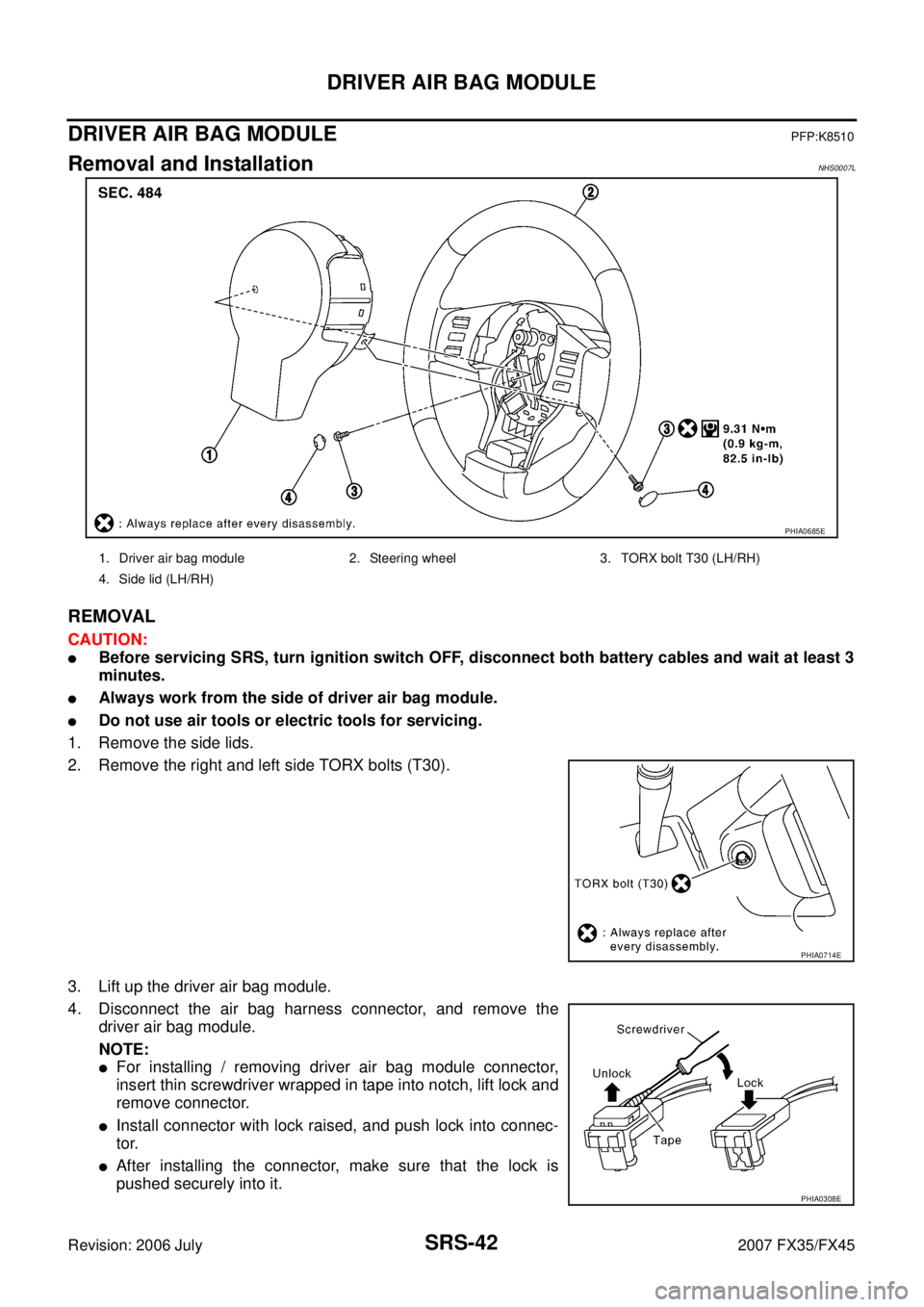
DRIVER AIR BAG MODULEPFP:K8510
Removal and InstallationNHS0007L
REMOVAL
CAUTION:
�Before servicing SRS, turn ignition switch OFF, disconnect both battery cables and wait at least 3
minutes.
�Always work from the side of driver air bag module.
�Do not use air tools or electric tools for servicing.
1. Remove the side lids.
2. Remove the right and left side TORX bolts (T30).
3. Lift up the driver air bag module.
4. Disconnect the air bag harness connector, and remove the driver air bag module.
NOTE:
�For installing / removing driver air bag module connector,
insert thin screwdriver wrapped in tape into notch, lift lock and
remove connector.
�Install connector with lock raised, and push lock into connec-
tor.
�After installing the connector, make sure that the lock is
pushed securely into it.
PHIA0685E
1. Driver air bag module 2. Steering wheel 3. TORX bolt T30 (LH/RH)
4. Side lid (LH/RH)
PHIA0714E
PHIA0308E
Page 4191 of 4366

SPIRAL CABLE SRS-45
C
D E
F
G
I
J
K L
M A
B
SRS
Revision: 2006 July 2007 FX35/FX45
INSTALLATION
Install in the reverse order of removal.
CAUTION:
�The spiral cable may snap by steering operation if the cable
is installed in an improper position.
�The neutral position is set as follows.
Turn quietly the spiral cable clockwise to the end position.
Then turn it counterclockwise (about 2 and half turns) and
stop turning at the point on which the stopper insertion
holes are in the same position.
The service part is installed in the neutral position by the
stopper and can be set without adjusting after the stopper
is removed.
�Do not turn the spiral cable rashly and also beyond the limit
number of turns. (These will cause cable snap.)
�Adjust the spiral cable locating pin (showed as A inthe fig-
ure) to the steering wheel locating pin hole (showed as C in
the figuer).
�Secure the air bag harness with the harness fixing hook.
�After the work is completed, make sure no system malfunc-
tion is detected by air bag warning lamp.
�In case that malfunction is detected by the air bag warning
lamp, reset by the self-diagnosis function and delete the
memory by CONSULT −II.
�In case that malfunction is still detected after the above
operation, perform self-diagnosis to repair malfunctions.
Refer to SRS-20, "
SRS Operation Check" .
PHIA0887J
Page 4194 of 4366

SRS-48
SIDE CURTAIN AIR BAG MODULE
Revision: 2006 July 2007 FX35/FX45
SIDE CURTAIN AIR BAG MODULEPFP:985P0
Removal and InstallationNHS0007O
REMOVAL
CAUTION:
�Before servicing SRS, turn ignition switch OFF, disconnect both battery cables and wait at least 3
minutes.
�Always work from the side of the side curtain air bag module.
�Do not use air tools or electric tools for servicing.
1. Remove headlining. Refer to EI-43, "
Removal and Installation" .
2. Disconnect side curtain air bag connector. NOTE:
�For installing / removing side curtain air bag module connec-
tor, insert thin screwdriver wrapped in tape into notch, lift lock
and remove connector.
�Install connector with lock raised, and push lock into connec-
tor.
�After installing the connector, make sure that the lock is
pushed securely into it.
3. Remove side curtain air bag module fixing bolts, and then remove the side curtain air bag module.
CAUTION:
�Always place the side curtain air bag module with the warn-
ing label facing upward.
�Do not disassemble side curtain air bag module.
�Do not insert any foreign objects (screwdriver, etc.) into air
bag module connector.
1. Side curtain air bag Inflator 2. Side curtain air bag 3. Bolt
4. Assist grip bracket 5. Bolt (There is no torque control)
PHIA0656E
PHIA0953J
PHIA0317E
Page 4211 of 4366
PREPARATION TF-7
C E F
G H
I
J
K L
M A
B
TF
Revision: 2006 July 2007 FX35/FX45
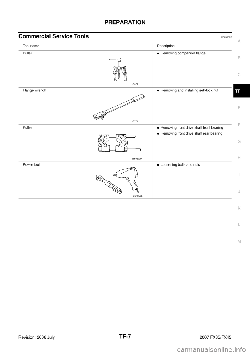
Commercial Service ToolsNDS0009Q
Tool nameDescription
Puller
�Removing companion flange
Flange wrench
�Removing and installing self-lock nut
Puller
�Removing front drive shaft front bearing
�Removing front drive shaft rear bearing
Power tool
�Loosening bolts and nuts
NT077
NT771
ZZB0823D
PBIC0190E
 3. Headrest holder (locked)
4. Seatback pad 5. Seatback trim 6. Seat cushion inner finisher
7. Screw 8. Seat")